Executive Committee Meeting
(Committee Members Only)
Session Start End
-
McDANIEL (KP Engineering, LP)
I am hoping this will be a record on the answering speed. KP and I believe that vacuum tower bottoms should be on the shell side. In most facilities I have reviewed, this is the setup they have on their vacuum tower bottoms versus crude. One of the reasons for putting a vacuum tower bottom on the shell side is that it generates an improved U (heat transfer coefficient) rate. You will have a lot less pluggage or less dP, being that you are normally only looking at a one pass on the shell side. In the worst case of a shutdown, you then would have an easier time trying to re-establish flow and get the process going again.
In terms of design guidelines, since we recommend that the vacuum tower bottoms be on the shell side, we are looking more at dP than at velocities. So, I will recommend a dP of around 5 psi (pounds per square inch). But if you have a system that is on the tube side, then I would probably look for a guideline of around 8 to 10 feet per second. Now the question points out, and I agree, that there is the dilemma with it being on the shell side: You will have an increased rate of deterioration on the U rate. That is a given, and you will probably start to experience some fouling. One client I know has this problem about every three to four months. But with the possibility of helical baffles on the shell side, you can see improved run-lengths and a lot better performance. Is that a record?
ROBERTSON (AFPM)
Close.
THEISS (Marathon Petroleum Corporation)
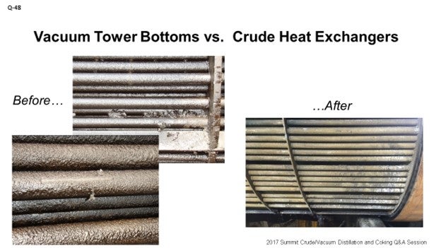
Just to echo what Ross said, in Marathon, we have similar opinions. We see better results of operational performance when the crude is on the tube side. Also, as Ross pointed out, helical baffles have shown a big improvement to some of the fouling we have had in the past. The picture you see on the screen is not apples to apples. The question was about VTB versus crude. The pictures are actually deasphalted pitch product versus crude. When we changed the design so that the crude was on the tube side, we saw better performance. On the slide, you can see the before and after.
GAMBOA-ARIZPE (CITGO Refining & Chemicals, L.P.)
I will be quick. The other panelists’ answers were fairly complete. In most exchangers, tube-side velocities are generally greater than shell-side velocities, as they both said. For this reason, the vacuum tower bottoms stream was usually routed through the tube side. This configuration in older exchanger designs – think ancient; so, wartime exchangers – ensured that the VTB stream would remain within the turbulent flow regime across the operating span of the exchanger; thus, minimizing fouling. This design concept, however, came at a high cost; because one, VTB pumps in set circuit needed to be equipped with sufficient head to accommodate the higher pressure drop that was associated with higher flowing tube side velocities, and two, larger exchanger diameters were also required to help manage the expected pressure drop. In most newer designs, the VTB – as they mentioned – is kept on the shell side. In this configuration, the head requirements on the system are much lower and the exchange of footprint is smaller. The tradeoff is that slightly higher fouling rates can be expected. These rates can be managed or mitigated with newer baffle designs or, as Ross mentioned, the helical exchanger design. In short, both design configurations can work as long as the implications of these other factors are properly understood.
GAMBOA-ARIZPE (CITGO Refining & Chemicals, L.P.)
Then some of you have wartime design units. [Laughter]
TARIQ MALIK (CITGO Petroleum Corporation)
I am going to keep it short. If there is one takeaway from this question it is that the viscose material always has to be on the shell side to give you a better heat transfer coefficient. That is number one.
Number two, you can always adjust the velocity and pressure drop you want, if you keep the higher viscosity material on the shell side. Five pounds design pressure drop is a little on the low side if you have a new exchanger. A kilogram/cm2 is more practical. A good design practice would be about 10 to 12 pounds, not quite a kg/cm2; or I should say, seven-tenths of a kilo. So, if you manage these correctly, you will have a very fouling-free life between turnarounds. If you put it on the tube side, the footprint will grow quite a bit. That exchanger shell, if it were 40 inches in diameter, will become 64 inches. And on the helical baffle, the shell will also grow.
That last point is that if you have HTRI [Heat Transfer Research Inc.] software, you can optimize the dimensions. You can put the viscose material on the tube side and see what results you get. Or you can put the viscose material on the shell side and see what results you get. It will give you a very high pressure drop in the tube side for VTB, if you go that direction.
UNIDENTIFIED SPEAKER
Right. Right.
WARREN LETSZCH (TechnipFMC)
Just a simple question. Do you guys have a minimum tube diameter on these exchangers to prevent fouling?
McDANIEL (KP Engineering, LP)
If you are putting it on the tube side.
WARREN LETSZCH (TechnipFMC)
Well, if you have your vacuum bottoms and your crude oil, something is going through the tubes. I am just wondering if there is a final minimum diameter at the bottom of an FCC and for the slurry exchangers down there. If they are too small, you will have plugging problems.
UNDENTIFIED SPEAKER
Probably looking more at like one inch.
WARREN LETSZCH (TechnipFMC)
One inch? Yes, okay. That is about what we use.
W. ROSS McDANIEL (KP Engineering)
KPE believes the typical design for a vacuum bottom versus crude exchanger is for the crude to be on the tube side and the vacuum bottoms to be on the shell side. Most facilities I see have this setup as well.
Some reasons for putting the vacuum resid on the shell side are to achieve higher U rates and hopefully avoid pluggage since the shell side is typically only one-pass.
As a design guideline, ∆P for vacuum resid on the shell side is at around 5 psi. If I were putting it on the tube side, I would probably say velocities of about 8 to 10 fps.
However, many operations do experience fouling on the shell side and thus, rapid U rate deterioration, which demands shutdowns for cleaning, sometimes as often as once a year, if cleaning online is unavailable. Installing helical baffles on the shell side is an option to consider helping mitigate fouling in low velocity areas and to improve operation.
JEREMY THEISS (Marathon Petroleum Corporation)
For all applications, we determine shell-side versus tube-side fluid based on fouling factor. In general, we have seen that the crude side has more fouling than the vacuum tower bottoms (VTB), thus putting crude on the tube side. A helical baffle design allows us to put the VTB on the shell side and not see any increased fouling rate. We target 8 to 12 feet per second on both sides of the exchanger to control fouling. The pressure drop is a function of velocity and flow rate.
Within MPC, we have two examples of helical baffle conversion and swapping the shell- and tube-side fluids. The exchanger’s original design had VTB on the tube side and crude on the shell side with a conventional baffle exchanger. We saw an extremely clean bundle upon the first inspection after the conversion.
LOGEROT (Prosys Inc.)
This question refers to advanced process control and several different aspects of APCs. Before I get into the details of the answers, I want to say a few words about what we mean when we say, ‘advanced process control’, or APC. In this answer, APC is a very, very wide subject. There are lots of different APC applications and APC methodologies.
In this answer, I will primarily concentrate on model predictive control (MPC). A quick description of model predictive control is that it is an approach that uses a process model. It will usually be a linear model that predicts the effects of control moves on multiple process parameters. The model not only predicts the moves, but it also predicts the future process movements and will write appropriate set points to key controllers in order to be able to drive the process to an optimum point. That is, the ultimate goal of MPC is to drive you to the optimum points.
Examples of using MPC: Crude unit optimization is really the first place where you would apply MPCs. The expected production of various cuts are inputs into the models, and then the MPC takes over to balance heat, heat transfer, energy consumption, and operating parameters against your target product mix and your target product quantities. MPC considers the impacts of key manipulated variables on all of the controlled variables in order to bring you operation of the crude Column Two at its optimum point and to maximize throughput, while also keeping within your various safety operability and quality constraints.
In the coking process, MPC is used to set furnace and coke drum operating parameters. Basically, you are trying to influence your product mix and, again, maximize your throughput. Downstream in the coker fractionation column, MPC could be very similar to what you are doing in the crude column. Other units in the refinery will also use model predictive control. Really, there are many different ones. It is really hard to explain all of them, so I will just leave it at that.
We will now start talking about the long-term and short-term goals. How does MPC support your long-term goals? First of all, once you have decided what crude stocks you are going to feed, the MPC must then have the flexibility to adapt to the crude feedstock are you using. Depending on the magnitude of the differences among the various crude, you might actually have to change predictive models based on the type of crude you are feeding into your crude column.
In supporting your short-term goals, obviously, the MPC application cannot change the composition of the crude you are feeding. What it can do is adjust itself to maximize the production of what you consider your more desirable cuts that you want out of your crude column. You optimize by increasing draws, changing sidestream duties, and adjusting other process parameters within the crude column in order to optimize. Get the most that you can out of the draws that are most valuable.
Alignment among MPC applications in the refinery is done with an overall refinery optimization tool which considers that the crude unit is not operating by itself. It has to operate in concert with every other unit in the refinery. It is a very broad topic to discuss. The optimizer will provide target values for key variables, key constraints, and cost factors for the crude unit that will allow it to operate in concert with the rest of the refinery.
As a side note, I will just wrap up by saying that we had a very interesting discussion about this topic in the OPCAT group yesterday afternoon. We were talking about the fact that you cannot just optimize one unit by itself; you have to optimize that unit in concert with the entire refinery. There will be a gentleman doing a presentation on this topic this afternoon in OPCAT. So, if you are interested in further information, we can begin with that first after lunch.
LÉGARÉ (Andeavor Martinez Refinery)
My slide starts off agreeing with the statement: “APC targeting goals should definitely be aligned on both short and long-term goals.” It is important that the APC goals be based on the product utility costs of the current operating period; that is, looking at your gasoline versus distillate or gas-to-diesel margin, natural gas costs, power cost, water cost, etc. An example I will give here, which will bring home my point, is the question of whether the crude fractionator stripping steam is being optimized to save on natural gas cost or to maximize recovery of gasoil. We were trying to do the latter; APC was trying to do the former. Once you figure that out, you can make the appropriate changes. In the meantime, money is being left on the table.
As far as goal alignment, the focus of the APC goal should always be on making the turnaround premise in both the crude units and downstream units. The example here is about the diesel T90 from the crude fractionator tower. Sometimes you can have a spike in distillate margin; for example, when everyone is driving up to see the total eclipse up in the Northwest. The refiner will want to cut deeper in his/her crude fractionator with the diesel draw to make more diesel. Well, what happens if you cut too deep and start impacting the catalyst performance and put into question your ability to make end-of-run on your diesel hydrotreater? So, it is important to communicate. In most refineries, this is the most efficient way to stay aligned on both short and long-term goals.
Have the Hydroprocessing engineers look at their reactor models to determine what that change in the T90 will impact, as far as making end-of-run on the diesel hydrotreater. Then, get back to the crude unit engineer and say, “Yes” or “No”. That being said, I am going to throw out that “it depends” comment. Sometimes those margins can be so strong that you will make enough money today and then take an unplanned shutdown to changeout the catalyst. So, be flexible, and communicate and understand how those current economics are driving short- and long-term performance.
The next point is about alignment. Alignment, for me, also translates into effectiveness and communicating effectiveness so that it is transparent to the organization. We have gone through the transition of measuring effectiveness in different ways. When you are learning how to crawl, effectiveness is measured based on whether or not APC is turned on or off. When you are learning how to walk, you start to look at the impact on operations and whether APC is actually driving control valve positions as intended. Lastly, when you are trying to sprint, you are starting to generate the actual benefits for which the APC systems are designed. A good idea is to communicate the benefits on a monthly basis while also communicating what you have left on the table by not optimizing your APC systems. I am sorry I am going to use APC where Darwin was using MPC. My understanding is that most refiners refer to this technology as AP.
Lastly, I think both Jeremy and I already said that it is important for refiners to have an identified individual or group that is focused on maintaining the data that is being used to optimize your APC so that it will be capturing current information. The previous example I gave was about operating a fractionator while trying to cut back on natural gas costs. Now we are really leaving money on the table, as far as not recovering as much gasoil as we want. It could just as simply be done by having someone spend a half-hour a week making sure APC is up to date with the costs of natural gas, gasoline, crude, etc. But also, it is a gap that I think several refiners have within their operating procedures. If we could do a better job on tracking current economic values, I think we would get a lot more value out of our APC systems.
THEISS (Marathon Petroleum Corporation)
Really quickly, I want to stress the importance of resources. When it comes to APC, we have seen general success when making sure that the process engineers and the process control engineers are up on the board and getting the buy-in from the operator. On night shift or afternoon shift, operators can turn off those APCs; and the next thing you know, you lack the data to continue to build a better APC program. So, we have seen a lot of resurgence in trying to get our folks up in the field talking to the board operators to make sure that they have the buy-in to continue to run these systems.
LOGEROT (Prosys Inc.)
I have to agree, in spades, with what both of these guys said. My quick follow-up is that you must have someone who is actually responsible for looking at the MPC application and making sure it is working. Because if you do not have someone who is dedicated to or at least responsible for watching that application and making sure that it is running correctly and doing what it is supposed to do for the operators, they will turn it off. That was already said. They will turn it off, and it will not be useful for you. So, we cannot emphasize enough that you have to commit those resources.
LÉGARÉ (Andeavor Martinez Refinery)
As folks are rolling out new APC systems in refineries and on specific units, one of the gaps I saw recently was really engaging the operators as part of that rollout and providing them with appropriate training. The reason is that it is too easy for the operators to put their hands up and say, “I do not know what this program is doing. I do not trust it”, and never turn it on. As I mentioned, there is a lot of money on the table when the APC program is working correctly. Make sure the operators have an intimate understanding of what the APC program it is trying to do. When one of their controllers is starting to take a different action from what they thought it would do, the operator will let the APC program take control and not deactivate it. The operators will become more aligned with the operation of APC, and the systems will be operated more efficiently.
ROBERTSON (AFPM)
That concludes the submitted questions. Before we turn off the recorder, I want to thank all of the panelists for their preparation and participation thus far in the session. We appreciate all of your efforts.
JEREMY THEISS (Marathon Petroleum Corporation)
Without proper resources and attention, Advanced Process Control (APC) technology may experience inconsistencies as applied to crude units. Refineries where crude slate varies frequently may struggle capturing the value that APC provides for steady controls and optimization. Mode-based APC may be applicable, but irregularities in crude compositions may still provide hurdles.
Our current APC practices focus at the unit level on multivariable interaction optimization to meet targets provided by product control. We have discussed “real-time optimization” (RTO), but we always struggle with the concept of an online optimizer fighting against a refinery planning LP model. In situations where RTO has not been utilized, production planning LP offline models and the APC applications are localized to achieve best unit level performance.
Industry experts do point out crude units as having the most potential for their application, and it is also the first “target” customers go after when implementing real-time optimization. Sites with multiple crude units have even more of a potential benefit. The thought of alignment of APC through downstream units is one of the primary justifications. Steady feeds from the crude unit should provide steady control to downstream units where APC is used. The hurdle in pursuing real-time optimization is having enough resources to maintain the application once it is installed.
Personal interactions between the those executing operating targets and production planning is the key mechanism for providing crude unit targets that are consistent with operating objectives, limits, or constraints. It is critical that the controls or APC engineer is in tune with the objectives and constraints to ensure alignment. A lack of alignment usually results in lower APC utilization metrics. Our target for APC performance metrics is greater than 90%. The metrics provide a weighting to the “effectiveness” of the controller, not just whether or not it is on. We measure effectiveness by providing an uptime for optimization functions, as well as the overall controller.
ERIC LÉGARÉ (Andeavor Martinez Refinery)
APC target setting and economic goals should be aligned to achieve both short- and long-term refinery goals. For example, is the APC optimizing around minimization of stripping steam based on a time when NG prices were high or is the goal to promote gasoil lift in the crude fractionator? APC may be driving you one way, while Planning wants to take the unit somewhere else.
Alignment should be a function of the Planning Group working with Operations to ensure that APC targets are in line with the short- and long-term plans. For example, process engineers at the crude unit and diesel hydrotreater can both get involved to ensure that the T90 of the diesel draw at the crude unit is in line with the feed quality specification provided to the catalyst supplier to verify that the diesel hydrotreater’s TAR premise is met.
Likewise, product economics and crack spreads should be reviewed against the APC targets as an aggressive change in your diesel T90 target to capture an unexpected spike in margins and can sometimes pay for an unplanned catalyst change.
APC targeting should integrate real-time costs around crude, products, and utilities: power, steam, and natural gas. The concern is ensuring that someone in your organization follows these parameters closely to be certain that your APC is always optimized around the most current economic model. There is concern around adoption of this approach as updates become less frequent over time.
APC effectiveness is measured to provide additional visibility to the organization. Andeavor has progressed from tracking just APC functionality to adding APC effectiveness. APC systems are monitored for “on” or “off” status and whether controls are actively controlling the unit’s operation. APC value is also tracked using industry APC economics to determine daily value being generated by each APC system in the refinery.
DARWIN LOGEROT (ProSys Inc.)
These two related questions will be covered as one unified answer. One can say, for sure, that there is a wide variety of Advanced Process Control (APC) applications that are used in today’s refineries.
Before getting into the details of the answer, a short summary of what is meant by APC is in order. There are two basic types of APC in use, and both are important in overall refinery optimization.
Model-Predictive Control (MPC): This approach uses a process model (usually linear) to predict the effect of control moves on multiple process parameters. The model not only predicts future process movement, but it will also write appropriate control setpoints to drive the process to optimum operation.
Advanced Regulatory Control (ARC): This approach does not rely on a process model. ARC employs interconnected PID control loops, custom programming, calculations, and/or logic to accomplish a specific control objective or set of objectives.
Some examples of the use of MPC include:
Crude Unit Optimization: This is the first application of planning targets. The expected production of the various cuts are inputs into the model. MVC then takes over to balance heat transfer, energy consumption, and operating parameters against the target product mix and qualities. MPC considers the impacts of key manipulated variables on all the controlled variables to optimize crude unit operation and maximize throughput, while keeping within safety, operability, and quality constraints.
Coking: MPC is used to set furnace and coke drum operating parameters that will influence product mix and maximize throughput. Downstream, MPC in the fractionator will be similar to those of the crude unit.
Other Units: The wide variability of unit arrangement within refineries prevents a ‘universal’ solution, but units such as reformers, FCC, hydrotreaters, hydrocrackers, etc. will generally also employ MPC to optimize operation with connectivity to the overall optimizer.
Examples of ARC applications are:
Furnace pass balancing,
Furnace firing and cross-limiting controls,
Coke drum switching automation (in conjunction with sequence controllers),
Boiler load balancing, and
Claus unit feed balancing and constraint controls.
As seen from the above examples, the MPC applications are generally those that are most important in overall refinery optimization and supporting operating goals. However, one should not downplay the importance of ARC in refinery operations. First, APC is generally easier and less expensive to implement. Also, their importance should not be overlooked. APCs work in concert with MPC applications to support the optimization goals. Good APC control applications improve the ability of MPCs to optimize the major refinery units.
As an example of MPC and ARC working in concert with each other is the crude furnace. The MPC will set the desired total charge rate and outlet temperature based on optimization targets. Then the pass balancing ARC sets the flow through each individual pass, and the firing control ARC determines the fuel and air rates required to meet those targets. Constraint control within the ARCs will feed back to the MPC when one or more operating parameter reaches a limit. The MPC must then adjust for the constraint.
Support of Long-Term Goals
Obviously, deciding which crude stock to feed to the unit is the first important choice a refiner must make in support of long-term goals, but this choice is beyond the scope of this answer. Once the feed is established, the crude unit’s MPC must have the flexibility to adapt to that feedstock. Depending on the magnitude of crude differences, the predictive models within the crude unit MPC may need to be adjusted to provide the best performance.
Support of Short-Term Goals
Obviously, an MPC application cannot change the composition of the crude feed, but what it can do is modify process parameters to maximize production of the more desirable cuts. Optimization is accomplished by increasing draw, changing sidestream duties, and/or adjusting other process parameters until the stream is at the edge of its specification range. This means that the maximum amount of the marginal components are included in the draw without throwing the total stream off-spec. Generally speaking, for an MPC app, the optimum operation lies at the edges of the acceptable operating range. The trick is that MPC is able to perform to efficiently control the process nearer to the edge of acceptable operation (several edges simultaneously!) than a human operator using single-loop PID controller is able to accomplish. This improvement at the margins can substantially increase a refinery’s profit. To use the driving analogy, “keeping it between the ditches” is replaced by “driving at the edge of the ditch without falling in”. The closer operation lies to the edge of the ditch, the higher the profits.
Alignment among MPC Applications
The relationship between the crude unit MPC, downstream MPCs, and the refinery’s planning goals is handled by an overall refinery optimizer. Again, this topic is much too broad to cover with a single answer, so this information is general in nature. This optimizer provides target values for key variables, key constraints, and cost factors for the crude unit MPC application. But if the MPC for the crude system is considered standalone and not coordinated with downstream units, then its capability will be limited. So, the optimizer also provides overall operating targets for all the refinery’s MPC applications.
The refinery optimizer balances operating goals (desired products quality and quantity) against individual unit capacities and capabilities. The individual MPCs optimize their respective units to maximize efficiency and throughput in support of the overall targets.