Question 48: What are your design and operating guidelines for vacuum tower bottoms versus crude heat exchangers such as minimum velocities, fouling rates, and pressure drop, and which process fluid should be on the tube side versus the shell side?
McDANIEL (KP Engineering, LP)
I am hoping this will be a record on the answering speed. KP and I believe that vacuum tower bottoms should be on the shell side. In most facilities I have reviewed, this is the setup they have on their vacuum tower bottoms versus crude. One of the reasons for putting a vacuum tower bottom on the shell side is that it generates an improved U (heat transfer coefficient) rate. You will have a lot less pluggage or less dP, being that you are normally only looking at a one pass on the shell side. In the worst case of a shutdown, you then would have an easier time trying to re-establish flow and get the process going again.
In terms of design guidelines, since we recommend that the vacuum tower bottoms be on the shell side, we are looking more at dP than at velocities. So, I will recommend a dP of around 5 psi (pounds per square inch). But if you have a system that is on the tube side, then I would probably look for a guideline of around 8 to 10 feet per second. Now the question points out, and I agree, that there is the dilemma with it being on the shell side: You will have an increased rate of deterioration on the U rate. That is a given, and you will probably start to experience some fouling. One client I know has this problem about every three to four months. But with the possibility of helical baffles on the shell side, you can see improved run-lengths and a lot better performance. Is that a record?
ROBERTSON (AFPM)
Close.
THEISS (Marathon Petroleum Corporation)
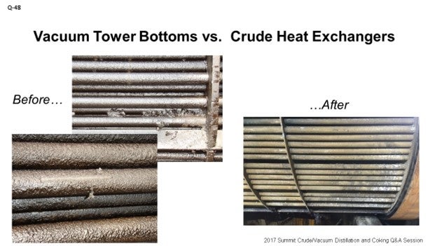
Just to echo what Ross said, in Marathon, we have similar opinions. We see better results of operational performance when the crude is on the tube side. Also, as Ross pointed out, helical baffles have shown a big improvement to some of the fouling we have had in the past. The picture you see on the screen is not apples to apples. The question was about VTB versus crude. The pictures are actually deasphalted pitch product versus crude. When we changed the design so that the crude was on the tube side, we saw better performance. On the slide, you can see the before and after.
GAMBOA-ARIZPE (CITGO Refining & Chemicals, L.P.)
I will be quick. The other panelists’ answers were fairly complete. In most exchangers, tube-side velocities are generally greater than shell-side velocities, as they both said. For this reason, the vacuum tower bottoms stream was usually routed through the tube side. This configuration in older exchanger designs – think ancient; so, wartime exchangers – ensured that the VTB stream would remain within the turbulent flow regime across the operating span of the exchanger; thus, minimizing fouling. This design concept, however, came at a high cost; because one, VTB pumps in set circuit needed to be equipped with sufficient head to accommodate the higher pressure drop that was associated with higher flowing tube side velocities, and two, larger exchanger diameters were also required to help manage the expected pressure drop. In most newer designs, the VTB – as they mentioned – is kept on the shell side. In this configuration, the head requirements on the system are much lower and the exchange of footprint is smaller. The tradeoff is that slightly higher fouling rates can be expected. These rates can be managed or mitigated with newer baffle designs or, as Ross mentioned, the helical exchanger design. In short, both design configurations can work as long as the implications of these other factors are properly understood.
GAMBOA-ARIZPE (CITGO Refining & Chemicals, L.P.)
Then some of you have wartime design units. [Laughter]
TARIQ MALIK (CITGO Petroleum Corporation)
I am going to keep it short. If there is one takeaway from this question it is that the viscose material always has to be on the shell side to give you a better heat transfer coefficient. That is number one.
Number two, you can always adjust the velocity and pressure drop you want, if you keep the higher viscosity material on the shell side. Five pounds design pressure drop is a little on the low side if you have a new exchanger. A kilogram/cm2 is more practical. A good design practice would be about 10 to 12 pounds, not quite a kg/cm2; or I should say, seven-tenths of a kilo. So, if you manage these correctly, you will have a very fouling-free life between turnarounds. If you put it on the tube side, the footprint will grow quite a bit. That exchanger shell, if it were 40 inches in diameter, will become 64 inches. And on the helical baffle, the shell will also grow.
That last point is that if you have HTRI [Heat Transfer Research Inc.] software, you can optimize the dimensions. You can put the viscose material on the tube side and see what results you get. Or you can put the viscose material on the shell side and see what results you get. It will give you a very high pressure drop in the tube side for VTB, if you go that direction.
UNIDENTIFIED SPEAKER
Right. Right.
WARREN LETSZCH (TechnipFMC)
Just a simple question. Do you guys have a minimum tube diameter on these exchangers to prevent fouling?
McDANIEL (KP Engineering, LP)
If you are putting it on the tube side.
WARREN LETSZCH (TechnipFMC)
Well, if you have your vacuum bottoms and your crude oil, something is going through the tubes. I am just wondering if there is a final minimum diameter at the bottom of an FCC and for the slurry exchangers down there. If they are too small, you will have plugging problems.
UNDENTIFIED SPEAKER
Probably looking more at like one inch.
WARREN LETSZCH (TechnipFMC)
One inch? Yes, okay. That is about what we use.
W. ROSS McDANIEL (KP Engineering)
KPE believes the typical design for a vacuum bottom versus crude exchanger is for the crude to be on the tube side and the vacuum bottoms to be on the shell side. Most facilities I see have this setup as well.
Some reasons for putting the vacuum resid on the shell side are to achieve higher U rates and hopefully avoid pluggage since the shell side is typically only one-pass.
As a design guideline, ∆P for vacuum resid on the shell side is at around 5 psi. If I were putting it on the tube side, I would probably say velocities of about 8 to 10 fps.
However, many operations do experience fouling on the shell side and thus, rapid U rate deterioration, which demands shutdowns for cleaning, sometimes as often as once a year, if cleaning online is unavailable. Installing helical baffles on the shell side is an option to consider helping mitigate fouling in low velocity areas and to improve operation.
JEREMY THEISS (Marathon Petroleum Corporation)
For all applications, we determine shell-side versus tube-side fluid based on fouling factor. In general, we have seen that the crude side has more fouling than the vacuum tower bottoms (VTB), thus putting crude on the tube side. A helical baffle design allows us to put the VTB on the shell side and not see any increased fouling rate. We target 8 to 12 feet per second on both sides of the exchanger to control fouling. The pressure drop is a function of velocity and flow rate.
Within MPC, we have two examples of helical baffle conversion and swapping the shell- and tube-side fluids. The exchanger’s original design had VTB on the tube side and crude on the shell side with a conventional baffle exchanger. We saw an extremely clean bundle upon the first inspection after the conversion.