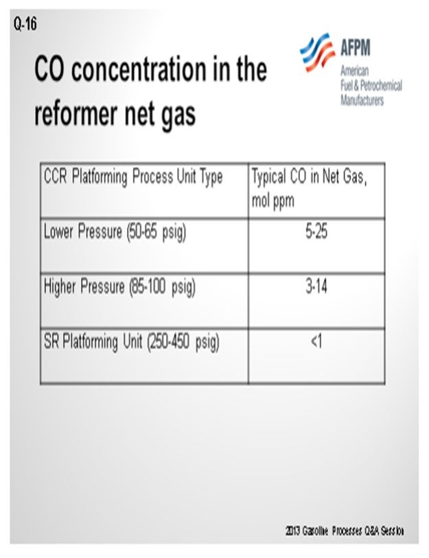
ADAMS (HollyFrontier Corporation)
HollyFrontier has two CCRs: one at Tulsa that was converted from a semi-regeneration reformer and one at Artesia. We have not done a catalyst change at the Tulsa refinery CCR, but we have done an online catalyst change at Artesia. Essentially, we just made up more catalyst and purged the catalyst out of the regeneration section. It took about four or five days to completely purge the old catalyst out and replace it with a new catalyst. The downside was that we spent more on catalyst; because as the new catalyst moved through the system, we ended up using 10 to 15% more in order to complete the purge.
BULLEN (UOP LLC, A Honeywell Company)
Based on our experience, we estimate that about 10% of the reloads have been on-the-fly-types of change-out, which equates to about three units a year. We have a procedure for how to do this. As Mark said, one typically has to use more catalyst than if doing a shutdown and change-out just to make sure all of the old catalyst is purged.
Some other issues involve catalyst handling. It can be difficult to get personnel to make sure they segregate the old catalyst from the new, resulting in accidentally putting the old catalyst back into the unit. So, a rigorous process is needed for that.
The circulation rate for the catalyst can be limited by the mechanical moving of the drums and the addition of the drums to the unit, so it may end up being necessary to change the operating conditions to accommodate the more-active catalyst to minimize the extra coke. As the new catalyst comes into the system, it generates a different quantity of coke than the old catalyst; so the operators must be aware that they have to go and adjust the regenerator conditions. One of the drawbacks of doing an “on the fly” type of change-out is that one cannot inspect the system; in particular, the reactors. If there are any issues related to the reactors, such as high ∆P (differential pressure; DP) or poor distribution of the reactor temperatures, those problem will still exist after changing the catalyst.
Finally, the density of the two catalysts – the old versus the new – can impact the circulation system: so be aware of those differences. Also, while oxidized catalyst can be used, this generally puts more stress on the regeneration system to dry out the extra water from the oxidized catalyst. Oxidized catalyst tends to have more water on it.
Finally, you tend to generate more fines when doing a “change-out on the fly”, so keep close attention on the dust collection system.
MELDRUM (Phillips 66)
One of our Cyclemax™ CCR units changed catalyst “on the fly” with such success that the next catalyst changes on another of our Cyclemax™ units will plan to use the “on the fly” method. Benefits include decoupling the catalyst change from a unit outage. The catalyst change mentioned used 106% catalyst to complete the changeover. I want to emphasize that you lose an opportunity to do some vessel inspections with the “on the fly” change. I also emphasize that dust formation is to be watched. In our experience, the reduction zone filter DP increased significantly, resulting in much more frequent changes of that filter. In my Answer Book response, I have provided some parameters used for the example I have referenced.
MARK ADAMS (HollyFrontier Corporation)
HollyFrontier has two CCRs in its system: Artesia and Tulsa. In Artesia, the CCR catalyst was changed while the unit continued to operate. The upside is that the unit continues to run. The downside is that 10 to 15% more catalyst is used as some fresh catalyst is purged along with the old catalyst due to mixing. At Tulsa, the catalyst in the CCR has not been changed since the unit started operation.
PATRICK BULLEN (UOP LLC, A Honeywell Company)
The basic principle of the “Change-out on the fly” procedure is that while the reforming unit continues more or less normal operation, used catalyst is continuously withdrawn from the unit and replaced with fresh catalyst. The used catalyst is removed from below the regeneration tower, allowing the coke to be combusted before unloading. The fresh catalyst is added into the catalyst circuit just below the withdrawal point using the normal catalyst addition system.
In recent years, UOP estimates that about 10% of all continuous reforming unit reloads have been done while the reactors continue to process feed and produce valuable products. The procedure can be implemented on all types of UOP CCR Platforming™ Process units (atmospheric, pressurized, and Cyclemax™ regeneration sections) and also many of the units designed by others. Using this procedure allows operators to capture the benefits of improvements in catalyst technology or to replace catalyst that is underperforming as a result of poisoning or operational problems without a complete shutdown of the reforming unit.
While the “Change-out on the fly” procedure is a simpler compared to a full unit shutdown, there are a number of issues that need to be considered in the planning stages.
• Catalyst handling, either of the fresh or used catalyst, is frequently the rate limiting step in the change-out procedure. The team responsible for catalyst handling will need to carefully plan how to safely and efficiently move and keep separate the drums of old catalyst and the new catalyst.
• While continuing to process feed and producing reformate and hydrogen, it may not be possible for the reactors to operate at design conditions. It is necessary to keep the coke level on the catalyst in a range that the regenerator can sufficiently burn off the used catalyst before it is removed from the unit. This may limit throughput and severity of reforming unit operations given the rate of catalyst circulation that can be supported by the catalyst handling arrangements. This is more likely to be an issue with larger units.
• The goal should be to execute the replacement of the catalyst as quickly as is safely possible so that unit operations with fresh catalyst can be optimized (with regard to feed rate, octane and product flow) and the system tuned to optimize performance with the new catalyst.
One of the significant drawbacks to replacing the catalyst in this way is that there is no opportunity for inspection of the reactor internals and the execution of maintenance on the reactor side of the unit. In particular, the use of the “Change-out on the fly” procedure is not recommended if there are any indications of catalyst flow problems or reactor internals’ damage (pressure drop or unusual distribution of reactor delta temperature). If there are unresolved issues with the internals, they will impact the performance of the unit with the fresh catalyst in the same manner as with the used catalyst.
There are several other issues related to “Change-out on the fly”:
1. Difficulties can occur when the density of the fresh and used catalysts are different. The unit circulation is calibrated on the used catalyst and care must be taken as the fresh catalyst goes to the regenerator and the mass through the regenerator changes. This may require changes to the regeneration section operation.
2. Changing out catalyst using oxidized fresh catalyst is generally not recommended, as there can be issues with increased water native to the catalyst along with the water generated by reduction. This increased load on the drying section of the regenerator can result in getting the Platforming™ unit wet.
3. There can be a tendency to generate more fines while doing a “Change-out on the fly”. The dust collector system will need to be closely monitored.
CRAIG MELDRUM (Phillips 66)
An example of parameters used for a change-out is as follow for a 35 kbpd (thousand barrel-per-day) Cyclemax™ unit with 200,000 lbs catalyst inventory and 3,000 pph (pounds per hour) catalyst circulation:
• The old catalyst is removed below the regenerator to minimize coke on the catalyst.
• Catalyst circulation is reduced to 50% of design.
• 106% of the catalyst inventory is changed-out at an average load rate of five drums per hour.
• Total personnel resources used are eight operators, 14 catalyst handlers, two crane operators, and two engineers.
• Logistics: 950 catalyst drums and 80 flow bins
SONI OYEKAN (Prafis Energy Solutions)
At my last oil refining company, we accomplished that catalyst replacement process successfully with the assistance of the catalyst/technology supplier. It is most important to get the catalyst and technology supplier technical experts and support on board early while the project is being considered as refiners do not frequently conduct “on the fly” catalyst replacements. Prior to initiating the “on the fly” catalyst replacement project, adequate planning is required with the assistance of the catalyst supplier, catalyst handling company, refinery technical service, and Operations, Maintenance and Environmental staff. The following are required:
• adequate catalyst supply,
• revised and updated catalyst on-stream replacement procedures,
• plans for reforming at moderate reforming severity process conditions to manage coke make for complete black burn operations,
• safe procedures for handling hot catalyst exiting the regenerator, and, of great importance,
• safe use of nitrogen.
The hot catalyst issue can be of greater importance depending on the type of CCR technology that the oil refiner is using. The oil refiner should also plan to potentially use 110 to 120% of system catalyst inventory as fresh catalyst since there will be some mixing of fresh and spent catalyst and since it will take a little more fresh catalyst to ensure complete spent catalyst replacement. The money invested in the CCR catalyst is not a significant issue as the unused catalyst would be used as makeup catalyst over the course of reforming operations.
Having written that, I must confess that I am not a strong advocate of “on the fly” catalyst replacement for a number of factors: I fully understand when refining business conditions call for and drive the need to use “on the fly” catalyst replacements. However, I am strongly in favor of the standard complete catalyst replacement.
The “on the fly” catalyst replacement option does not provide the opportunity to conduct an appropriate reformer turnaround to permit full inspections and necessary repairs in the reformer reactors, catalyst transfer equipment, and regenerator sections. In addition, it does not permit inspecting and conducting necessary repairs to the chloride reduction equipment and system for meeting RMACT 2 regulations for regenerator vent gas. Sometimes the application of the “on the fly” catalyst replacement could encourage the refiner to operate without a turnaround for years longer than that recommended with consequent post-“on the fly” catalyst replacement reformer and regenerator performance and reliability problems that, over time, could negate any economic benefits realized via application of the “on the fly” catalyst replacement.