Question 84: Discuss your considerations for improvement of power recovery train reliability.
Year
2014
Process
Stuart Kipnis (Grace Catalysts Technologies)
Refiners have created operating flexibility during hydrotreater outages by utilizing Grace’s clean fuels GSR® additive technology.
Proper management of FCC feed hydrotreater outages becomes increasingly important as more and more refiners rely on hydrotreating to meet their per gallon gasoline sulfur limits. Running at higher severity increases the frequency of turnarounds. Conventional methods of insuring that the gasoline pool staysbelow the sulfur limit during the hydrotreater turnaround are purchasing low sulfur feed or reducing FCC throughput. Either approach can significantly reduce refinery profitability. An alternative is to use one of Grace’s gasoline sulfur reducing technologies during the outage to provide operational flexibility while maintaining sulfur compliance and profitability.
One such example of a refiner that used Grace GSR® 5 sulfur reduction additive during a feed hydrotreater outage is shown in Figure 1. The refiner was able to process higher than typical feed sulfur and maintain gasoline pool sulfur compliance. Use of GSR® 5 began two months prior to the 45-day feed hydrotreater outage. During that time, feed sulfur increased by as much as 35%. The three periods represented are typical operation (Base Period), GSR® 5 before and during the outage where gasoline sulfur reduction ranged from 20-25%, and finally GSR® 5 following the outage.
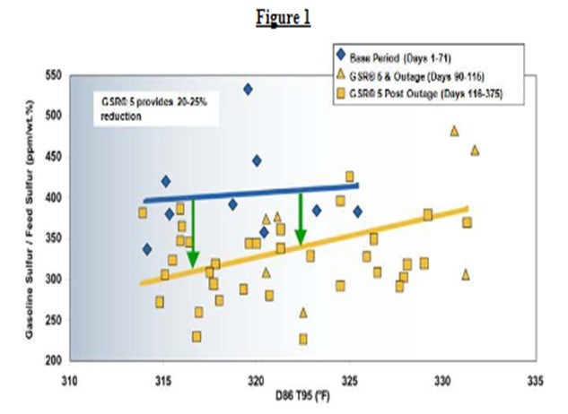
The customer estimated that use of GSR® 5 netted $1.7 millions of savings during the hydrotreater outage. The results were so encouraging that the customer elected to continue using GSR® technology, switching to a SuRCA® catalyst and operating with post outage feed sulfur 10-15% higher than the typical operation. This change to their operation grew annual profits by approximately $8 million.
Continued operation during a hydrotreater outage is just one way that refiners can benefit from application of Grace’s patented GSR® technologies. In-unit reduction of FCC gasoline sulfur creates a variety of opportunities and options for refiners to drive profitability while meeting new Tier 3 gasoline requirements.
Grace’s GSR® clean fuels solutions create economic advantages around:
• Feedstock blending
• Asset optimization to:
• Preserve octane
• Maximize throughput
• Extend pre-treatment and/or post-treatment hydrotreater life
• Gasoline stream blending options
• Generation of gasoline sulfur ABT credits to defer capital investment
Tier 3 regulations require the reduction of average gasoline pool sulfur level to ≤10 ppm with an 80-ppm cap by January 2017, compared to the current limit of ≤ 30ppm with an 80-ppm cap. Grace has substantial experience in similarly demanding environments like Japan.
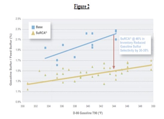
In the mid 2000’s, Japan committed to lower gasoline sulfur. As early adopters of more stringent gasoline quality regulations, Japanese refiners faced similar challenges that US refiners face today in meeting Tier 3. Since 2005, these refiners have successfully utilized Grace GSR® products to maintain compliance, observing 35%-40% reduction in the gasoline sulfur / feed sulfur ratios allowing them to meet the 10 ppm gasoline specifications. An example of a Japanese refiner meeting 10 treater severity can be seen in Figure 2. In this case, as much as 35% gasoline sulfur reduction was achieved with SuRCA® catalyst.
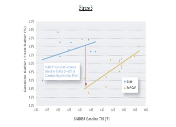
Another example [Figure 3] shows a Japanese refiner that was able to maintain compliance with the 10 ppm gasoline sulfur spec while maintaining flexibility to either blend high sulfur coker gasoline into the gasoline pool or extend the VGO hydrotreater catalyst life. Again, SuRCA®catalyst technology was and the refiner observed approximately 40% reduction in gasoline sulfur.
Grace GSR® technologies: D-PriSM result of almost two decades of innovation. Grace GSRFCC applications worldwide delivering 20%burn operations. The GSR® additive technologies are used at a 10%the catalytic solutions are a customized 100% drop can be used for short- or long-term applications; the longest continuous application is now 12 years.
Grace’s multiple product offerings allow for a truly Tier 3 compliance plan. Ask your Grace representative which product is best for your operation.
Reference: 1L. Blanchard, C. Borchert, M. Pu, NPRA Annual Meeting, 20072 L. Blanchard, T. Oishi, B. Teo, J. Haley, "SuRCARefineries", Catalagram® 98, 2005
Greg Savage (NALCO Champion)
There are several possible uses for slurry oil. It can be recycled to the FCCU feed for destruction. However, it is quite resistant to cracking and does not give good gasoline yields. Today, some major uses for FCC slurry oil are:
•Blending stock for heavy fuel oil
•Carbon Black Oil (CBO)
•Feedstock for production of needle coke
•Feedstock for the delayed coker to reduce furnace fouling
•Feedstock for fixed bed hydrocracker or ebullating bed (H-Oil) conversion processes
Heavy fuel oil is normally the lowest value disposition for slurry oil. Depending on the ash content and the viscosity, significant quantities of low viscosity blending stock must often be used to meet fuel oil specifications.
If the quantity of catalyst fines in the slurry oil can be reduced to 0.05 wt. % and other specifications met, the slurry oil can be upgraded to Carbon Black Oil (CBO). FCC slurry oil is an important source for carbon black oil. The upgrade value of slurry oil from heavy fuel oil to CBO can be significant.
For the production of needle grade coke, slurry oils can be used to increase the aromatics content of the feed. Again, however, the ash must be reduced to avoid adversely affecting the coke quality. Decant oil can reduce fouling at the coker furnace, however, it can reduce overall coker liquid yield.
When used as hydrocracker feedstock, the ash contained in the slurry oil often causes plugging of the catalyst pores in fixed bed processes and reduces the degree of conversion achieved. In ebullating bed processes, the ash contained in the slurry can cause erosion problems in the ebullating pumps used in the process.
Brian Devlin (NALCO Champion)
Slurry oil is typically sold into the fuel oil and carbon black feedstock markets. Both fuel oil and carbon black purchasers will impose a % ash maximum. Exceeding the maximum will reduce the value of the slurry, and in some contracts will trigger a price penalty. Reducing ash is accomplished by allowing the ash to settle in tankage before sale. If the process is too time consuming, or does not achieve the desired ash reduction an ash settling chemical may be recommended.
Kenneth Bryden (Grace Catalysts Technologies)
The increase in the quantity of tight oil as a percentage of the North American crude slate has resulted in numerous changes at refiners. Tight oils, like other light sweet crudes, have a much higher ratio of 650°F- to 650°F+ material when compared to conventional crudes. Bakken tight oil has a nearly 2:1 ratio, while typical crudes such as Arabian Light, have ratios near 1:1. A refinery running high percentages of tight oil could become overloaded with light cuts, including reformer feed and isomerization feed, while at the same time short on feed for the fluid catalytic cracking unit (FCCU) and the coker. Some refiners have balanced the use of larger amounts of tight oil with increased use of heavier crudes such as Canadian Syncrude. Other refiners have charged a portion of whole tight oil to the FCC to keep the FCC full.
As refiners consider new feedstocks, testing is a valuable tool to reduce risk. Testing provides understanding of feed properties and potential yield changes. Below are examples of potential tests to use when evaluating a new feedstock.
Testing of feed metals levels is especially important since tight oil derived feeds often contain varying levels of conventional contaminants such as sodium, nickel and vanadium and unconventional contaminants such as iron and calcium. Understanding the expected metals levels of a new feed allows refiners to work with their catalyst vendor to choose catalyst options that mitigate the challenges of these metals. Grace’s newest catalyst family, ACHIEVE® catalyst, is designed to address the unique challenges associated with tight oils. ACHIEVE® catalyst formulations are flexible, enabling Grace to design a custom solution for refiners proactively increasing the amount of tight oil in their crude diet.
Feed properties such as API, concarbon and hydrocarbon types can provide insight into the expected crackability of a feed but may not tell the whole story. A fuller understanding of how a feed will crack in a unit can be obtained through testing. Either bench-scale testing (ACE or MAT) or pilot-scale testing (such as Grace’s DCR™ circulating pilot plant) can be done. MAT and ACE testing have the advantages that they are easy to set up and require small amounts of material.2 However, these units cannot provide the detailed product analysis or feedback on extended operation that pilot scale units can. Larger scale test equipment such as a pilot unit can provide sufficient liquid product for distillation and detailed analysis (such as API gravity and aniline point of LCO produced, viscosity of bottoms, octane engine testing of gasoline, etc.) and can provide information on continuous operation. Additionally, compared to bench scale units, the DCR pilot plant has the advantage that it mimics all the processes present in commercial operation and it can operate at the same hydrocarbon partial pressure as a full-scale commercial unit. An example of the use of testing to understand the cracking tight oil derived feeds and the effects of operating variables in processing these feeds can be found in Reference 1.
Grace’s technical service and R&D teams help refiners assess potential challenges from feedstock shifts before they occur via feed characterization, feed component modeling, and pilot plant studies. Understanding feed impacts earlier provides an opportunity to optimize the operating parameters and catalyst management strategies, enabling a more stable and profitable operation.
References:
1.“Processing Tight Oils in FCC: Issues, Opportunities and Flexible Catalytic Solutions, AM-14-16,” 2014 AFPM Annual Meeting, Orlando, FL.
2.“Predicting FCC Unit Performance with Catalyst Testing,” PTQ Catalysis 2013.
Ann Benoit (Grace Catalysts Technologies)
Maximizing light cycle oil (LCO) is largely a slurry management process. To increase LCO, refiners can simply change operating conditions and lower catalyst activity to shift operations into a lower conversion regime. The negative impact of shifting to a lower conversion regime is that this shift will typically decrease volume swell and also increase bottoms, unfavorably impacting profitability. The true challenge is to maximize LCO without producing incremental bottoms while maintaining volume expansion. In general, refiners tend to focus on the following strategies to maximize LCO yield:
1.Distillation changes (reduce gasoline end point and increase LCO endpoint)
2.Feedstock
•Removal of diesel range material from the FCC feedstock
3.Recycle Streams
•Heavy cycle oil (HCO) or bottoms
4.Operating Conditions
•Lower reactor temperature
•Higher feed temperature
•Lower equilibrium catalyst activity
5.Catalyst Optimization
•Increased bottoms conversion
•Lower zeolite-to- matrix surface area
•Maintenance of C3+ liquid yield and gasoline octane
A quick, simple and effective way to increase LCO is to make distillation adjustments such as lower gasoline endpoint and/or increased LCO endpoint. Flash point specification and main fractionators salting often will determine how low a refiner can reduce the LCO initial boiling point (reduce gasoline end point).1 Maximum main fractionator bottoms temperature, slurry exchanger fouling and diesel hydrotreating constraints will often determine how much the LCO endpoint can be increased.
Regarding feedstock, it is recommended that diesel range material be removed from the FCC feedstock. This material is typically higher quality diesel for the overall refinery diesel pool.
Recycle streams can be employed to fully maximize LCO at reduced conversion. The quality of the recycle stream can make a difference in the products being produced. The effects of different recyclestreams are discussed in detail in the AFPM paper “Strategies for Maximizing FCC Light Cycle Oil” (Hunt, et al, AM-09-71). The 650°F – 750°F recycle stream produced the most LCO and gasoline at the lowest coke for a given conversion.1 However, this stream is not produced in sufficient quantities to fully maximize LCO. The 650+°F and 750+°F streams have high Conradson carbon levels (consistent with higher quantities of tetra-aromatics and heavier compounds) which limit the yield of LCO when these streams are recycled to the FCC.1 The 650°F to 800°F or 650°F to 850°F recycle streams produced the highest LCO when recycled against a coke burn and bottoms constraint.1
Adjustments to operating conditions such as reactor temperature, preheat, and/or catalyst activity to lower conversion and increase LCO can be made, but this may come with a price. By reducing conversion through operating conditions, LCO yield and potentially cetane will increase2, but so will slurry. The primary challenge in the FCC unit is to increase LCO, while minimizing incremental slurry yield and maintaining volume swell. Gasoline octane may also be a concern due to lower reactor temperature and lower conversion. This is why a catalyst reformulation strategy is needed to address the incremental slurry, lower volume swell, and lower gasoline octane when operating conditions are adjusted to maximize LCO.
Application of the correct catalyst technology is critical for high LCO yield and minimal bottoms and coke yield. Keep in mind that a balanced approach is required to achieve maximum bottoms upgrading to LCO and other valuable products. An LCO maximization catalyst is typically an improved bottoms cracking catalyst with a lower zeolite-to-matrix ratio. Grace typically considers our MIDAS® technology in LCO maximization applications due to premium high matrix bottoms cracking ability. Due to the economic penalty with lower volume swell, ZSM-5 additives such as OlefinsMax® or OlefinsUltra® should be considered to maintain or improve volume swell and/or gasoline octane while operating at a lower conversion. If butylene has a greater value than propylene, a reformulation to the Grace’s Achieve® 400 FCC catalyst could be optimal.3 Achieve® 400 features a moderate Z/M ratio and dual-zeolite functionality, delivering increased gasoline octane and butylene yield at minimum bottoms.
There are several avenues that can be taken to increase LCO yield on the FCC, but overall refinery economics will dictate which move or combination of moves proves the most beneficial to the refinery. Catalyst reformulation strategy should always be considered in LCO maximization cases since this can address the incremental slurry and lower volume swell in a lower conversion regime.
John Aikman (Grace Catalysts Technologies)
While there are several operational and mechanical factors that can influence a unit’s particulate emissions, the question asks specifically about the FCC catalyst; as such, the following discussion will address characteristics of fresh catalyst only.
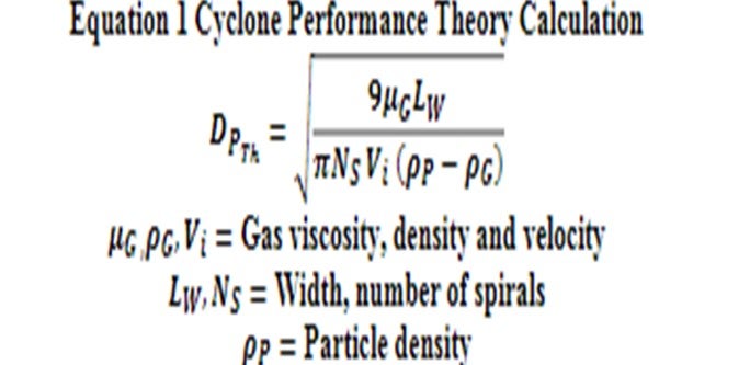
There are four basic characteristics of FCC catalyst that can have direct effects on particulate emissions. These same characteristics will also affect particulate losses to the fractionator and slurry product. The first characteristic is simply the amount of fines content coming into the unit with the fresh catalyst due to the manufacturing process. Figure 1 is an example of a typical fresh catalyst particle size distribution, with a theoretical depiction of a cyclone’s ability to retain fresh catalyst particles. DPTh is the smallest particle diameter which can reliably be collected by a cyclone and is used to model cyclone performance. Particles below this size will be lost by the cyclone.
A review of the Grace Ecat database showed that none of the FCCU’s in North America can retain any 0-20 μ range particles. In addition, they only retain an average of approximately 4.0 wt% in the 0-40 μrange. Fresh catalyst typically ranges anywhere from 9 to 16% of 0-40 μ depending on the supplier andmanufacturing process. Some units require higher amounts of 0-40 μ range particles to help with circulation.
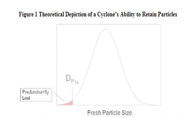
The next characteristic of fresh catalyst that must be considered is the particle density. he DPTh mentioned above will decrease with increased catalyst particle density, per Equation 1 below. This means that cyclones can retain smaller particle sizes as the particle density increases. This is due to the centrifugal force acting on a heavier particle. However, particle density is not the same as apparent bulk density (ABD). Industry typically measures and reports ABD as part of the routine Ecat analysis, but this should not be mistaken for particle density for cyclone efficiency purposes. Since Al2O3 is denser than SiO2, catalysts with higher alumina content will have higher catalyst particle density.
The third characteristic is the inherent attrition resistance of the fresh catalyst. Industry measures the attrition resistance via a variety of tests, with the primary goal of providing a relative indication of catalyst attrition resistance. Grace utilizes the DI test or Davison Index. On the DI scale, a lower number is less likely to cause attrition and generate microfines. It is usually not valid to compare attrition resistance results obtained from different laboratories. Additionally, it is important to note that the energy applied to a catalyst sample during attrition testing is much more severe than commercial conditions.
As discussed above, the majority of the microfines created in the FCCU will leave the unit through either the reactor or regenerator cyclones, with the latter potentially contributing to increased particulate emissions at the stack.
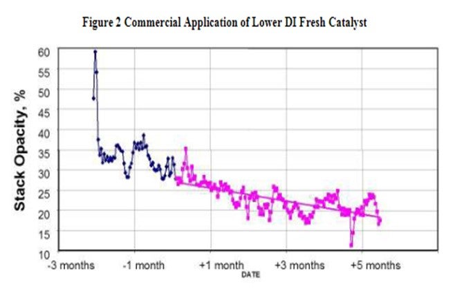
'The attrition resistance of the catalyst is a function of the manufacturing process and the binder material utilized during the manufacturing process. Figure 2 is an example of how a refiner improved the FCCU stack opacity with catalyst formulation. The reduction was achieved changing to a Grace supplied catalyst with lower DI and lower 0-40 μ content in the fresh catalyst.
The final characteristic of fresh catalyst that affects particulate emissions is its morphology. Morphology can be defined as the study of the form and structure of a particle and its specific structural features. A catalyst particle that has a smoother exterior surface is less likely to generate microfines in an FCCU. Even catalysts with a low fresh DI measurement can cause increased particulate emissions if there are surface irregularities resulting from the manufacturing process. In order to demonstrate this visually, Figures 3 and 4 present SEM’s (scanning electron microscopy) of “bad” and “good” fresh catalyst morphology for a side-by-side comparison.
Figure 3 and 4 SEM’s of Fresh Catalyst (magnified X250)
“Bad Morphology” “Good Morphology” In conclusion, there are several characteristics of fresh catalyst that can be controlled to reduce particle losses and thereby reduce flue gas emissions. Specifically, to lower emissions the fresh FCCcatalyst should possess the following characteristics: a particle size distribution with an optimal range of 0-40 μ particles, higher catalyst particle density, lower DI, and superior morphology. Grace’s alumina-sol technology provides superior binding to the catalyst particle leading to best-in-industry attrition resistance. The versatility and performance of alumina-sol catalysts coupled with Grace’s manufacturing capability, have resulted in wide-market acceptance and as a result, Grace is the preferred FCC technology for loss sensitive units around the world.
