Closing Remarks
Question 27: What options are refiners considering addressing upcoming Tier 3 Fuel Standards [10 wppm (weight parts per billion) annual average sulfur in gasoline]?
STREIT (KBC Advanced Technologies, Inc.)
Tier 3 fuel is lowering sulfur yet again in gasoline. The crude oil sulfurs have been coming down also with the tight oil, so some people have asked the question: Is processing more tight oil actually going to get us on-spec on Tier 3? The answer is no, not really. It is not going to have that significant of an impact on your gasoline sulfurs, obviously, without other processing.
As of right now, it does not seem like there is a lot of capital being mobilized to meet Tier 3 specs. There are people who are doing things, but they not building as many new units as you might think or not doing quite as many sizable revamps. Many places are tied in with their investments to be on-spec for Tier 2. They are trying to exploit those facilities to get on-spec for Tier 3 with the addition of, say, a polishing reactor on the backend of a gasoline desulfurizing unit. Some places are trying to add more catalyst into that existing unit to try to get the sulfur down.
Some refiners have discussed exporting gasoline blendstocks in order to be able to get on-spec on Tier 3. It does not look like a long-term option because there is not a market that will support that for very long, if it is currently available in your area anyway. Some places have discussed increasing gas oil hydrotreating. One of the drawbacks to putting all your eggs in that basket is that if you have problems with the gas oil hydrotreater, then you will not be able to make gasoline. If you have desulfurizing on the backend, you are relying on a unit that is inherently a little more reliable or less likely to trip off and cause you problems. It is just something to keep in mind if that is a solution that you are considering getting on-spec on Tier 3.
Another problem coming up with making 10 ppm sulfur gasoline is that blendstocks which did not used to be a problem may now be one. A lot of places that did not ever think about how much sulfur their butane stream contained are now realizing their butane has 7 ppm, 10 ppm, or 12 ppm sulfur just depending on its source. In those cases, you might actually have to put in a facility to remove the sulfur from butane. Many people think of alkylate as sulfur-free. It is not. It can contain as high as 7 to 20 ppm sulfur, so you must be aware of that. I think the main options being considered right now are trying to expand on the solutions to get on-spec for Tier 2. It does not look like there is not a lot of capital at this time which is being mobilized to do anything different.
MELDRUM (Phillips 66)
Current sulfur specifications in the finished gasoline are 30 ppm with an average 80 ppm on a cap, reducing down to 10 ppm, on average, with an anticipated cap of 50 ppm effective in 2017.
In Phillips 66, we will exploit the previous Tier 2 compliance projects as much as we can, but that is not going to get us to a solution in all cases. We will be expending quite a lot of capital in order to meet those Tier 3 regulations, either from polishing units or building some additional one into the refinery process.
I have provided a table showing a typical Tier 2 blend to give you a feel for the order of magnitude of where the sulfur is coming from within the streams. You will notice the two dominant areas of focus will be for the straight-run and cat naphtha streams. Straight-run treatment is fairly straightforward with some conventional or mild hydrotreating. You can expect expected to see about 1-number octane loss in that stream.
The cat naphtha streams are a different story. If traditional methods are employed to treat that stream, you can expect to see as much as a 10-number octane drop in that stream. That is not acceptable in almost all cases, so “advanced” hydrotreating technologies have been developed which utilize the characteristics of the light cat naphtha compared to the heavy cat naphtha. Light cat naphtha has few light mercaptans and a lot of olefins; heavy cat naphtha has a lot of sulfur and few olefins. A simplified process description is as follows:
Treat the full-range cat naphtha with a mild hydrotreating to convert the light sulfur compounds (the mercaptans) into a heavier sulfur compound through thioetherification. The naphtha should also be treated with minimal olefin saturation, fractionation to separate the light from the heavy naphtha streams, and additional treatment of the heavy cat naphtha to remove the sulfurs, disulfides, and thiophene conversion. Expect octane loss with this process sequence to be a 2- to 4-number drop.
Another process is the absorption removal of sulfur compounds, the S-Zorb process, which achieves sulfur compliance with about a 2-number octane drop.
I want to echo what Eric mentioned: Some of the streams which had not been given much attention in the past (butane and extraction raffinate) might need additional treatment and/or washing to meet final blend specifications.
CHRIS GREEN (Marathon Petroleum Corporation)
With regard to the butane sulfur, do you have any comments about dealing with dimethyl sulfide in butane? Also, what strategies can you use to remove dimethyl sulfide and reduce the butane sulfur?
STREIT (KBC Advanced Technologies, Inc.)
I think in most cases what I have seen is all mercaptan-based. So, I am not personally aware of anyone dealing with dimethyl sulfide, specifically, in the butane stream. I would imagine that means you will have to route it to a naphtha hydrotreater or something like that to get that material out. I have not personally seen anyone who had to do that yet.
DAVID SMITH (UOP LLC, A Honeywell Company)
A number of adsorbents have been utilized in a regenerative mode to remove dimethyl sulfide and dimethyl disulfide from C4 streams, either butane or mixed C4 (butane, butenes) streams. There are high capacity molecular sieves for the removal of these sulfur compounds if it is a paraffinic stream. The product AZ-300, a hybrid adsorbent, has widely been used to remove these sulfur-based contaminants from both butane and butane streams. It is not economically feasible to remove hundreds of parts per million of DMS (dimethyl sulfide) or DMDS (dimethyl disulfide); but if you have relatively low concentrations, adsorption is an attractive option for their removal.
JESSY TRUCKO (UOP LLC, A Honeywell Company)
I want to add to that comment. Typically, the DMS follows the C5 stream; so, you should be looking for about a 1.4 reflux-to-feed ratio in your debutanizers. In addition, as you mentioned, we have also done some combinations of Merox™ and adsorbent, which allows us to achieve less than 1 ppm sulfur in the product. BULLEN (UOP LLC, A Honeywell Company) If you do need a hydrotreater, UOP sells LPG hydrotreaters. We do not design them very often, but the technology does exist. Question 27: Answer Book Responses
CRAIG MELDRUM (Phillips 66)
Tier 3 regulations for finished gasoline reduce the sulfur specification from 30 ppm average (80 ppm cap) to 10 ppm average (anticipated 50 ppm cap), effective January 2017. Typical Tier 2 compliant gasoline blend data clearly indicates that lowering finished gasoline sulfur will focus on straight-run and cat naphtha treatment (see table in shown below). Pushing process units used for Tier 2 compliance to maximum severity is not expected to provide full compliance with Tier 3 specifications; additional treatment projects are expected.
Straight-run treatment is best achieved with mild hydrotreating (typical parameters of 350 to 500 psig, 300 to 700 scfb, and 5 to 8 LHSV). It is expected to see less than 1 octane number loss in the stream. If used, conventional treatment of cat naphtha (700 psig, 1000 scfb, and 2 LHSV) is expected to result in as much as a 10 octane number loss; therefore, advanced hydrotreating technology is used to give the needed desulfurization with only a 2 to 4 octane number loss.
Advanced hydrotreating recognizes the characteristics of light and heavy cat naphtha (HCN) fractions. LCN (light cat naphtha) is characterized with few light mercaptan sulfurs and a lot of olefin. HCN is characterized with a lot of sulfur and few olefins. Three treatment steps are used: 1. Full-range mild treatment for light sulfur conversion (mercaptans to heavy sulfur compounds through thioesterification) with minimal olefin saturation, 2. Fractionation of LCN and HCN, and 3. Conventional treatment of HCN (sulfides, disulfides, and thiophene conversion). Another technology is absorption removal of the sulfur compound, such as the S-Zorb process. The octane loss is expected to be 2 numbers. Butane treatment and additional aromatic extraction raffinate washing may be needed.
ERIC STREIT (KBC Advanced Technologies, Inc.)
Most refiners are apparently not mobilizing much in terms of external capital. Many invested in Tier 2 regulations and are primarily looking to extend the solution that they already have. They are either doing this internally or asking the current licensor to provide options for expanding the capability with a minor investment of a polishing reactor or something similar. Upgrading or expanding gasoline desulfurization units to reach the new sulfur level will result in an even greater octane loss in the treated naphtha than is currently seen.
Some refiners have discussed getting to the Tier 3 sulfur level with gas oil hydrotreating only. Although this may be possible, there are risks involved with this strategy. Gas oil hydrotreating removes the coke-producing material from the FCC feed. Increasing hydrotreating severity in the past has caused problems with FCC heat balances in several locations. Further increasing severity to try to get to Tier 3 compliance will cause further problems with FCC coke formation for many units. Also, hydrotreater cycle length may have to be decreased significantly to reach the new desired sulfur levels. In addition, relying only on an upstream hydrotreater to be able to meet the gasoline specification increases the risks associated with unplanned shutdowns of those units. During an unplanned shutdown of the gas oil hydrotreater, the refinery would not be able to make gasoline. With a gasoline desulfurizer, rates may be able to be reduced enough that some gasoline could still be produced during an unplanned gas oil hydrotreater shutdown.
Some refiners took full advantage of credits while meeting Tier 2 regulations to avoid additional octane loss. If there is a similar credit arrangement with the Tier 3 legislation, it is possible. Tier 2 precipitated a significant build-out of treatment facilities for refiners to meet the 30 ppm specification. Early movers generated credits that were useful. The incremental investment and associated timeline to startup will be less varied to go from Tier 2 compliance to Tier 3 for most folks.
Some refiners may need to look into treating streams previously considered diluents. Butane, for example, has not typically been treated to remove sulfur because the sulfur level of the butane was below the sulfur level of the gasoline. Now, that same butane stream may need to be treated to remove the small amount of sulfur that it contains.
Exporting sour naphtha will not be a feasible long-term solution for anyone. The outlets to the south will eventually close. There could be some transient opportunities for units with treating capacity to take some sour naphtha in the short term.
ROBERTSON (AFPM)
Before we get to the last question, I just want to remind you that the Gasoline P&P is this afternoon. It is subtitled, “Alkylation 101”. Robert Ohmes with KBC and Joe Zmich with UOP are the champions of that topic. I encourage you to attend, if those subject interests you.
Question 28: Is the changing quantity of pentanes and pentenes in refinery streams and tightening gasoline regulations leading to operators considering different processing strategies in order to maintain gasoline blend pool specifications? Comment on increased pentene alkylation, decreased pentane isomerization, or other disposition sources.
ADAMS (HollyFrontier Corporation)
The pentenes, also called amylenes, can be fed to the alkylation unit and be alkylated. However, you make a lot of ASO (acid-soluble oil), and the yield is not that great; so, most people prefer not to do it. We do not alkylate our amylenes at the moment. If you need a place to get rid of olefin or have some other constraint that is really expensive, then you may be forced into that situation.
As far as isomerization, the only reason that we will decrease isomerization is if we have excess octane in the gasoline pool; and with the ethanol-blended gasolines, we need less octane. Most likely, we would back out other feedstocks. These feedstocks might be cheap, and we could drop them into the gasoline pool. So, it is really an economic decision about your interest in backing out butanes and natural gasoline and creating RVP in your refinery by putting a light straight-run through an isomerization unit.
One final comment: You might have an isomerization unit and discover a lot more pentanes than would be beneficial in isomerizing. Not all isomerization units were built with a deisopentenizer in front of the unit. The addition of a deisopentanizer is a relatively cheap way to open up some isomerization unit capacity by removing material that is not going to get converted in the isomerization unit anyway.
STREIT (KBC Advanced Technologies, Inc.)
There is some talk of increased pentene alkalization or amylene alkalization, but it does not seem like there are very many projects on the books to move in that direction. Whatever your alkylation unit can handle is worth investigating. Although as Mark pointed out, it probably cannot handle a lot.
With respect to the isomerization units, I talked about them before. Generally, their values and throughputs are getting reduced. In some cases, they are being shut down because of the RVP increase. It just depends on your refinery layout. In most cases, you have the ability to increase your reformer to make up that octane that you are going to lose by not isomerizing; so, it is not like you necessarily need the octane from the isomerization unit. If you do not need that octane and cannot handle the RVP increase, then what else are you going to do other than stop isomerizing?
So, what are you going to do with the pentanes? This has been a question for a while, and no one has come up with a really great solution for it. There are a couple of places you can route the pentanes now. You could put it in the hydrogen plant and make hydrogen out of it. The problem is that natural gas is so cheap right now, why would you want to use anything but natural gas to make hydrogen? The other possibility is just to send it off to chemicals, if you have access to some place that needs a light naphtha.
One other possible strategy is to increase your gasoline endpoint. That will give you more RVP soak on your gasoline pool, and you might be able to handle more light material in that pool at the same RVP. However, directionally this is not a very economically attractive idea because current economics support reducing gasoline endpoint to maximize distillate production.
MARK ADAMS (HollyFrontier Corporation)
Historically, octane has been the most important constraint on the gasoline pool in most refineries. Reduced octane requirements in ethanol-blended subgrades are changing that. Pentenes from the FCCU or coker are 90 RON and 77 MON. Alkylation is a possibility, but the volume shrink and ASO generation are rarely worth the trouble unless the gasoline pool is constrained by MON or olefin content in the gasoline. FCCU pentenes usually go to gasoline blending. Isomerization debottlenecking projects may look attractive since isomerization helps with benzene reduction. A deisopentanizer can be added upstream of the isomerization unit to bypass isopentane in the feed around the unit, opening capacity for convertible C5s and C6s.
CRAIG MELDRUM (Phillips 66)
Initial questions on C5 alkylation have been asked, but not much action has been taken thus far. Some considerations about C5 alkylation, provided by Daryl Dunham of UOP, include the following:
• More gasoline yield but not as much as anticipated. Stoichiometry and density calculations would indicate 1 bbl (barrel) C5 = + 0.96 bbl iC4 - 1.6 bbl alkylate. BUT, hydrogen transfer occurs; therefore, 1 bbl C5 = + 1.25 bbl iC4 - 1.12 bbl C9 + 0.45 bbl C8 + 0.32 bbl iC5. Since alkylate is C5+ gasoline, then iC5 is included for a total of 1.89 bbl of C5+ at 30% conversion. At 60% conversion, 1 bbl C5 = + 1.55 bbl iC4 - 0.64 bbl C9 + 0.90 bbl C8 + 0.65 bbl iC5 or 2.2 bbl of C5+ at 60% conversion.
• Increased iC5 production
• Lower gasoline RVP as C5s is converted to gasoline: nC5 RVP is 15.6 psi; iC5 RVP is 20.4 psi; C8 RVP is 1.0 psi; and C9 RVP is 0.5 psi.
• Lower alkylate RON and increased alkylate T90 (5 number drop in RON and 100°F increase in T90 when moving from a mixed PB stream with 10% C5 = to a 100% C5 = feed).
• Increased ASO production (more “stuff” comes into unit as feed gets heavier).
ERIC STREIT (KBC Advanced Technologies, Inc.)
There is growing concern regarding the quantity of light naphtha available relative to total gasoline volumes. This requires some head-scratching to create innovative solutions to this potential bottleneck. There are certain areas of the country where light naphtha cannot be blended into the pool while meeting volatility specifications and are Therefore, sold at a discount. Some refiners are considering alkylating pentenes from FCC gasoline as a means to reduce gasoline pool RVP to allow for upgrading light naphtha in isomerization units. However, not many projects have been announced to date. Most reformers are running at much reduced severity due to the decreased octane demand associated with increased ethanol blending. As a result, they may have some flexibility to increase severity to compensate for lower light naphtha octanes resulting from decreased pentane isomerization. Another possible destination for pentanes is to feed them to a hydrogen plant. This may not be economical because natural gas is so inexpensive, but it is an option. Finally, increasing gasoline FBP (final boiling point) may allow a refiner to soak up more RVP in the gasoline pool. Directionally, this is not desired because it converts more valuable diesel into gasoline. However, if it helps to get a refiner in terms of gasoline RVP, it may need to be considered.
ROBERTSON (AFPM)
Those are the responses from the panel. Since there are no additional comments or questions from the audience, we will now conclude the Gasoline Q&A session. I want to thank the panelists for the great job they did today and for all of their work over the last couple of months. I also want to thank Allen Kaiser for being the coach for this group.
Question 29: What are the industry practices to take samples around high-pressure equipment which contain light hydrocarbon and H2S? How do you ensure the samples are handled safely and representative of sample stream?
SHARPE (Flint Hills Resources, LP)
Our Corpus Christi and Pine Bend refineries had standardized on Texas Sampling Incorporated samplers. They provide a variety of closed-loop captured sample systems. We have a Sampler Selection Procedure Flowchart that helps us walk through ‘yes’ or ‘no’ decisions considering high RVP (Reid vapor pressure) material, high-pressure material, high temperature material, high H2S (hydrogen sulfide) options, and plugging potential. One caution is that if you install temporary sample stations, you will then have to take into consideration the options regarding the pressure. This is a very simplified flow diagram compared to what we use at the refinery. I cleaned it up a little, but the flowchart just illustrates the process.
If you are going to use temporary sample stations, you will need to make sure you are using the appropriate PPE (personal protective equipment); for instance, for pulling H2S Drägers when you are sulfiding. You can also use engineering controls to reduce your sampling, especially during sulfiding, by using online analytical capabilities provided by companies like Reactor Resources and others. These controls reduce the need for pulling Drägers during a rather hazardous part of your operations.
CHRIS STEVES (Norton Engineering)
These samples should be collected in a high-pressure sample cylinder using a flow-through arrangement. The sample return line must be connected to a lower pressure portion of the process (such as a compressor suction) or to the flare. The sample cylinder and the sample tubing should have valves right at the very end where the connections are made to minimize any product that will end up trapped between the valves. Once connected, the valves are opened long enough to purge the sample line and ensure that a representative sample is collected.
Question 30: What are your design practices for reactor skin thermocouple requirements in a hydrotreater and a hydrocracker for startups and safe operation?
VICHAILAK (Marathon Petroleum Corporation)
Our minimal requirement for a hydrotreater is three skin thermocouples at the top and bottom heads of the reactors and a full skin thermocouple at the bottom shell of the reactor just about at the tangent line. The option now is a full skin thermocouple at the top of the shell and the middle of the shell.
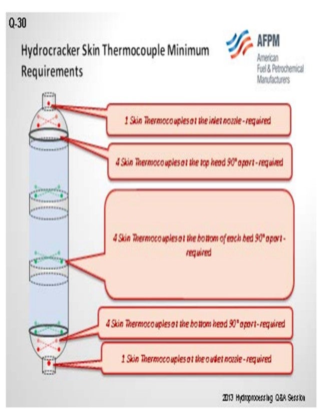
For a hydrocracker, we have one skin thermocouple at the inlet and outlet nozzles of the reactors. This slide shows a typical hydrotreater. It has just three skins at the top and bottom heads and then four skins at the bottoms shell; the other two are optional. For a hydrocracker, we have an additional one at the inlet and outlet nozzles; plus four at the top and bottom heads and four at the bottom of each bed. Those are all of the required thermocouples. These are the minimum requirements, but you can have more. Most of our reactors have four skin thermocouples.
The skin thermocouple should be provided to ensure the attainment of minimum pressurization temperature (MPT) on both startup and shutdown. I must emphasize that when doing the startup, you have to look at the bottom of the reactors for the MPT. And then when shutting down, your perspective is reversed: The top of the reactor becomes the MPT limit. You have to depressure the unit before you hit that temperature. The location of the thermocouples should be sufficient to safely start up and shut down the hydrotreater. High pressure hot separator may be required to have skin thermocouples as well.
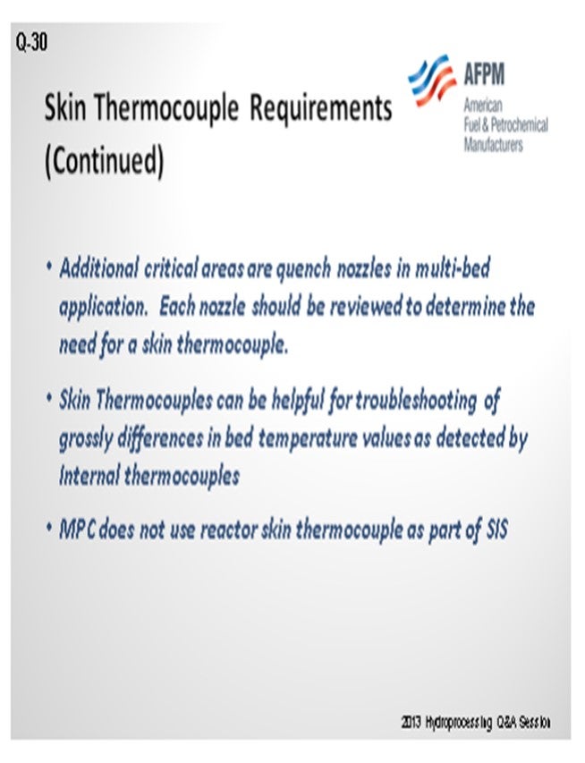
Additional critical requirements are a quench nozzle and skin thermocouple. It can be helpful to determine the temperature differences inside the reactor, which we have seen. We have seen a 50° difference in the skin thermocouples, which confirms what happened inside of reactors. However, we do not use reactor skin thermocouple as part of the Safety Instrument System.
SIVADASAN (UOP LLC, A Honeywell Company)
UOP generally designs all of their Unionfining™ and Unicracking™ reactors with skin thermocouples. These skin thermocouples are mainly provided to ensure that the vessel temperatures are above their ductile-to-brittle transition temperature and that the vessels do not exceed their maximum design temperatures during their end-of-the-run. These thermocouples also detect some localized wall heating due to the hotspots in the catalyst bed. Sometimes these reactor skin temperatures are also used to put a limit on the ∆T (delta T; temperature differential) between the reactor skin and the catalyst beds.
So, most of the Unionfining™ reactors have a ring of thermocouples at the bottom of the bed, and one more ring is provided at the bottom of the reactor shell.
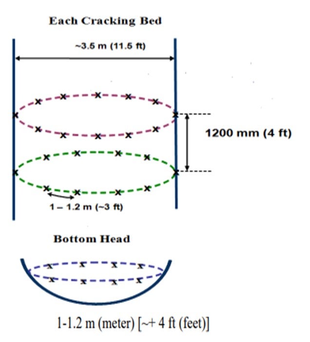
For hydrocracking units, the design is more or less similar to the Unionfining™ unit; except that this in case, there is an additional ring provided on top of the bottom bed and spaced four feet apart from the bottom ring. Also, the thermocouples are staggered in such a way, so they are in between the thermocouples on the bottom ring.
GATES (Motiva Enterprises LLC)
The skin thermocouples are placed on the vessel head and then on the thicker part of the shell itself. They are there to monitor the temperature of the vessel in order for us to understand when pressurization is allowed or when depressuring is required during shutdown. Your primary concerns are the temper embrittlement and hydrogen embrittlement of the low-chrome vessel itself. As an additional comment, at Shell, we do not use this as part of the automated depressuring system.
JON PRUDHOM (UOP LLC, A Honeywell Company)
What do you do if the reactor has a skirt? Do you tend to put thermocouples on the skirt?
VICHAILAK (Marathon Petroleum Corporation)
Right now, it is not required for us to put a thermocouple on the reactor skirt. For MPT, we normally look at the shell at the bottom head, mostly when starting up. I have talked to our metallurgists about whether we should have a skin thermocouple at the nozzle which is exposed to air. Most of the time, that part is not really covered; so it will be cooler. We do use IR (infrared) to shoot the skin temperature at the flanges, but we do not have actual skin thermocouples on the skirt or at the flanges.
ROBERT TORGERSON (Gayesco International)
Over the last year and a half, we have seen the requirements go up tremendously for this type of instrumentation. We literally have customers ordering hundreds at a time, which is probably leading to some of the questions here. What is interesting for us, though, is that there has been a significant change in the type of thermocouple. This transition has moved away from the traditional versions to one that is removable and online, which seems to help the reliability. If it is easy to replace, it tends to get replaced. With this design, the thermocouples are accessible as opposed to some of the traditional designs. When the points go out and are not changed out, the measuring point is lost.
MONTRI VICHAILAK (Marathon Petroleum Corporation)
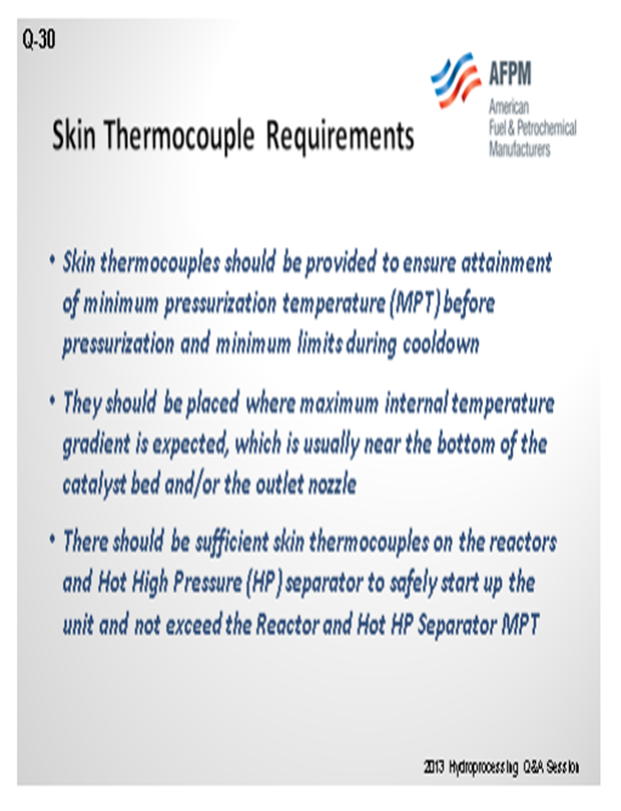
Skin thermocouples should be provided to ensure attainment of minimum pressurization temperature (MPT) before pressurization. They should be placed where maximum internal temperature gradient is expected, which is usually near the bottom of the catalyst bed and/or the outlet nozzle.
MPC minimum recommendations for skin thermocouples on hydrotreating reactors are:
• 3 skin thermocouples at the top head 120° apart (required),
• 3 skin thermocouples at the bottom head 120° apart (required),
• 4 skin thermocouples at the top shell 90° apart, relatively close to the tangent line (optional),
• 4 skin thermocouples at the mid-shell 90° apart (optional), and
• 4 skin thermocouples at the bottom shell 90° apart, relatively close to the tangent line (required).
An additional critical area is the quench nozzles in multi-bed application. Each nozzle should be reviewed to determine the need for a skin thermo couple.
For the hydrocracking reactors, we installed the following skin thermocouples:
• 1 skin thermocouple reactor inlet nozzle,
• 4 skin thermocouples per reactor bed located 90° apart,
• 4 skin thermocouples on the bottom reactor head located 90° apart, and
• 1 skin thermocouple on the reactor outlet nozzle.
There should be sufficient skin thermocouples on the reactors and hot HP separator to safely startup the unit and not exceed the reactor and hot HP separator minimum pressurization temperature (MPT). In some situations, skin thermocouples can be helpful for troubleshooting gross differences in bed temperature values as detected by internal thermocouples.
RAJESH SIVADSAN (UOP LLC, A Honeywell Company)
Skin thermocouples have been installed on most Unicracker™/Unifiner reactors. The thermocouple coverage and layout have been designed to:
• Ensure vessel temperatures are above ductile-to-brittle transition temperature during cold pressurization,
• Ensure peak vessel temperatures are within mechanical design limitations at EOR conditions,
• Detect localized wall overheating due to hot spots in the catalyst bed, and
• Detect the ∆T between the Rx (reactor) wall and the catalyst bed.
The number of the skin thermocouples depends on the reactor diameter.
UOP typically designs catalyst beds containing hydrotreating catalyst, with one ring located at the bottom of each bed and one ring located on the bottom head.
For catalyst beds containing cracking catalyst, two rings per bed are provided. One ring will be located at the bottom of the bed. The other ring will be located 4 feet (1200 mm) above the bottom ring. The top ring is staggered such that skin couples are located radially in between those in the bottom ring. In addition, one ring is also provided on the bottom head.
ROBERT TORGERSON and SYDNEY GARRETT (Gayesco International)
Online availability and reliability of skin temperature measurement for reactor skins is critical. This importance has caused many refiners to transition from traditional washer and stud style skin thermocouples and unreliable magnetic skin thermocouples to much more maintenance friendly “ski slope” guide tube designs.
The washer style thermocouple is a standard for many refiners, but it requires a variety of crafts (and associated permits) for replacement, which can be time-consuming. Commonly, this may include the following personnel:
1. Sheet Metal worker (for removal of protective skin),
2. Insulator (for verification and removal of insulation),
3. Mechanical/maintenance staff (for removal of nut),
4. Welder (for reattachment or repair of bolt stud),
5. Instrument tech (for replacement of washer thermocouple),
6. Insulator (for reinsulating of site), and
7. Sheet Metal worker (for repair of protective skin).
On the other hand, magnetic thermocouples can be problematic in that they lose magnetic force as the magnet rises in temperature, making them susceptible to detachment from the reactor.
The “ski slope” guide tube designs involve a specially designed temperature pad connected to a guide tube that gently curves up and away from the reactor and penetrates through the insulation and protective sheet metal skin. The thermocouple or RTD (riser termination device) is held in place by a fitting on the end of the tube which allows for a single craft (single permit) replacement of the thermocouple, thereby saving time and money. Because it becomes so quick and easy to replace a thermocouple with the ski slope design, they are more likely to be replaced when necessary, allowing the reactor to operate with a full complement of skin thermocouples for protection.
One of the “basic rules of thumb” for temperature measurement is to have 10 thermocouple diameters in parallel contact with the surface being measured. This allows for a consistent reading that eliminates any false impression due to temperature wicking through the metal of the probe itself. The “ski slope” design has this built into it, as does the aforementioned washer style thermocouples, but it is much more difficult to accomplish with magnetic style reactor skin thermocouples or other tip sensitive designs.