Question 40: What is your experience, design and opportunities for on-line crude blending coupled with near infra-red?
Year
2018
Process
BRANDON PAYNE (SUEZ Water Technologies & Solutions)
Cracked feedstocks can be introduced into the crude unit from several sources; the most common of which in North America are diluted bitumen from Canadian sources, diluted crude oils from South American sources, and slop streams from cracking units onsite that are recycled into the reprocessed slop oil blended into the crude unit feedstream. Asset operators have experienced unanticipated issues due to the reactive nature of these cracked stream components in previously unanticipated areas of the unit.
Fouling in the crude unit preheat train and the fouling of distillation column sections are common consequences of the introduction of cracked stocks in the unit feed. Due to the nature of the contaminant (i.e., recoverable hydrocarbon), adjustments in desalting practices will not remove or affect the behavior of these materials in the preheat train or distillation column. Additionally, traditional crude preheat antifoulant treatment chemistries are generally designed to disperse precipitated particulates, not address the polymerization issues associated with cracked materials. Depending on the boiling range of the cracked stocks, fouling could occur in sections of the distillation column where fouling had not previously been a concern. However, there are several practices that can be implemented that will aid in the mitigation of these potential issues when the need to process cracked hydrocarbon feedstocks arises.
The first suggested mitigation is the segregation of cracked material whenever possible. The ability to tightly control the introduction of this material to the unit is critical in managing its detrimental effects in unit equipment. If complete segregation is not reasonably achievable, the second suggested mitigation is to minimize the volume of reprocess (“slop”) material that will be contaminated with the cracked stocks. (It will prove to be a significantly more manageable issue to deal with 3,000 barrels of contaminated material than 75,000 barrels of contaminated material.) A third suggested mitigation is the routing of cracked stocks to an appropriate secondary processing unit instead of routing to the crude slop oil system. This will minimize the unintended fouling of the crude unit equipment. A fourth suggested mitigation is the implementation of a robust antifoulant treatment program that will address potential polymerization issues resulting from the processing of cracked materials. If an antifoulant chemical treatment program is in place, ensure that the treatment protocol addresses the polymerization potential and monitor accordingly.
DENNIS HAYNES and CHRISTIAN LEEDLE (Nalco Champion)
There have been successful applications in the desalting process to remove iron and calcium to varying extents. The ability to remove either of these contaminants depends upon their form. Some methods of removal may include pH suppression of the desalter wash water, elevated wash water rates and optimization of mud wash practices, application of solids wetting chemistries, and may also include, in some limited cases, extraction of a portion of interface has been used to minimize iron and calcium containing solids. The method used depends on the element being removed (iron or calcium), the form it is in, and the amount that is targeted for removal. Generally, for calcium (in the form of calcium naphthenates), the removal rate may be as high as 80-90%. For iron, the removal rate varies depending on the technology applied; it may be 20-50% in some cases, but with enhanced methods may be as high as 90%.
LANCE COX (NALCO)
The benefits of increasing the cycles of an open-recirculating cooling tower include cost reductions for:
Water - Purchased and Waste treatment.
Chemical Treatment – Raw Water Clarification and Waste Treatment
Electrical Costs – Pump Requirements
Capital Cost Deferral – Plant Capacity Expansion via Utilities Optimization vs. Replacement
Plant Infrastructure Spending – Minimize Maintenance Spend on Existing Caused by Capacity Limitations or Reliability Issues (i.e., Piping with Reduced Volumetric Capacity)
Operationally, especially as production units are debottlenecked over time, increasing tower cycles could facilitate the ability to utilize existing Utilities Infrastructure. This minimizes the need to undergo a disruptive engineering and installation processes should unit capacity enhancement projects be identified. This also aids in speeding those projects to fruition.
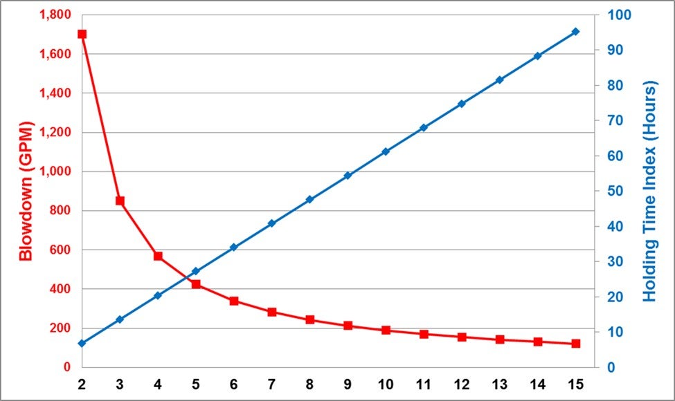
Certain reliability implications will be experienced to varying degrees. Increased cycles will impact the Water Quality, which can impact each heat exchanger in the circuit. A higher ionic species in the water will need to be evaluated from various aspects, including corrosivity, scaling and emissions (Air - PM10/2.5 and Receiving Bay TDS Regulations). The advent of enhanced treatment chemistries has broadened the acceptable operating window of these systems, while preserving performance capabilities. That said, the impact upon emissions should always be observed along with the diminishing returns as cycles increase. The non-linear characteristic of cycles vs. blowdown rate shows the sharp decline as cycles increase beyond the 5 to 8 level, while the Holding Time Index (HTI) increases steadily. (See Figure) HTI is one stress which becomes evident with respect to the treatment chemistries and crystal development characteristics, potentially leading to mineral scale deposition. The percentage of make-up water flow blown down from the cooling tower can be calculated by taking inverse of the cycles level. This states that the % of the tower make-up flow blown down will DECREASE from 20% (5 Cycles) to 10% (10 Cycles).
Reliability is only partially determined by Water Quality. The design characteristics of the exchanger circuit and individual exchangers are critical. Stress factor impact on heat exchange surfaces, such as Skin Temperature, Flow Velocity and Heat Flux will be exacerbated by a change in Water Quality. Each exchanger should be evaluated with respect to its design and how the water is changing. This analysis could require adjusted control strategies, including different limits, chemical treatment products, and possibly tighter control expectations. A thorough analysis of the various Mechanical, Operational and Chemical aspects of the system should be included in the decision to increase cooling tower cycles.
ALEC KLINGHOFFER (Coffeyville Resources)
The first question you should ask when considering what "safe park" mode means would be is the air blower running or not?
If the air blower is not running, things you should consider are ensuring all ignition sources are shutdown, bypassed or isolated (ESP, torch oil, DFAH, CO Boiler). Verify all hydrocarbon sources to the reactor, riser and regenerator are closed (fresh feed, any recycles, torch oil, fuel gas purges, LCO quench, etc.) and all sources of air are not being injected (main air, plant instrument air, fluffing air, etc.). Consider isolating by blocking in, DBB or blind as a stabilizing action. Confirm slide valves are closed and maintaining a positive ΔP (3-5+ psig). Close fuel gas to furnaces unless feed or fractionator bottoms oil circulation is maintained. Confirm you have steam to air blower(s) discharge, feed riser, feed & torch oil nozzles. Verify steam purging of reactor to the fractionator is controlling the reactor pressure greater than the fractionator and greater than the regenerator by 2+psi. Verify steam to MAB discharge is being injected at the prescribed rate. Verify steam to feed nozzles matches design curve specification. *If steam is not available, then use nitrogen (very large volumes of nitrogen will be required for cooling, due to its very low heat capacity). If neither steam, nor site nitrogen are available, then source a contract nitrogen vaporizer as soon as practical. Verify that the MAB discharge line is clear, and that MAB check valve has closed. Check status of Wet Gas Compressor (WGC) — in some units the WGC auto trips on blower shutdown, the reactor pressure must be higher than the fractionator and the regenerator to prevent flow reversal. If unit has a power recovery turbine, ensure that flue gas quench system is preventing the PRT inlet temperatures from exceeding limits. The vapor spaces of the regenerator and flue gas system must be purged before restarting the MAB. Use N2 or steam in enough quantities for 3 volume changes from the purge point to the stack. Sample gas in regenerator and flue gas system for combustibles. Ensure steam is dry, preferably superheated. Oil soaked on catalyst will crack to form explosive gases. In addition, steam passing through catalyst at temperatures above 1000°F will make HYDROGEN and CO via the water gas shift reaction. When purge is complete, and gases are verified to be free of combustibles, air can be introduced to the unit and catalyst circulation restarted. This must be done as SLOWLY as possible. Temperatures must be monitored to ensure no rapid rises. If there are rapid temperature rises, must go back and repeat purge and combustible check.
MINAZ MAKHANIA (UOP)
If the air blower is running, confirmation feed has been bypassed with isolation valves closed, again DBB or blind as a stabilizing action. De-energize ESP. ESP should not be re-energized until the flue gas has been verified to contain no combustibles and is below the acceptable CO levels. Nitrogen or steam to Riser at rates adequate to keep Reactor as high-pressure point (Reactor>Main Fractionator and Regenerator). Set Reactor at the highest pressure in the system. We specify pressure differential because required flow rates will be different under varied conditions. Pressure conditions are constant under all scenarios. Steam to feed nozzles at design curve specification (feed nozzles are very prone to plugging in the posture). Monitor vessel velocities to prevent exceeding velocity and temperature limits. Confirm slide valves are closed and maintaining a positive ΔP (3-5+ psig). Main Fractionator to steam pressure control. Use torch oil to control regenerator temperature. Maintain levels in Main Fractionator and GRU. Conduct extensive catalyst loss monitoring.
TIFFANY CLARK (BASF)
Standby #3, in a situation where the air blower is running, and catalyst circulation is being maintained, this can be a difficult operation to control long term and has significant risk associated. A big risk being detonation of ESPs that has occurred in the industry.
Major things to consider in this mode of operation to ensure safety are:
De-energizing ESPs until stable operation is reached, and monitoring the flue gas system upstream of the ESP regularly for hydrocarbon and CO.
While circulating catalyst, you should always maintain isolation between the Regenerator and Reactor/Main Fractionator by pressure balance.
And then, while most ESD systems will trip the feed isolation valves closed for you, you should always verify feed has been bypassed and that the isolation valves are closed and not leaking by.
Other things to verify include that you have adequate oil flow through Main Fractionator bottoms system so as not to build up catalyst. A sufficient level in the Main Fractionator should be maintained at all with adequate flush to tankage.
Nitrogen or steam to riser/stripper should be maintained at rates adequate to hold Reactor pressure as the highest pressure in the system by at least 2+psi. You should closely monitor the Reactor-Regenerator pressure balance, fluidization and catalyst circulation stability to prevent oxygen from entering the Reactor. The Main Fractionator should be on steam or nitrogen pressure control and adequate steam to the feed nozzles is required to prevent plugging the nozzles and should be consistent with design specifications.
You also want to monitor velocities and catalyst levels to prevent excessive catalyst carryover during this mode of operation. Monitor your slurry ash content and Regen fines or Scrubber solids content frequently and conduct extensive catalyst loss monitoring.
While torch oil is being used to maintain Regenerator temperature, it should be monitored very closely to prevent exceeding temperature design limitations and significant catalyst de-activation. You should adjust catalyst circulation rates to prevent temperature excursions or excessive thermal cycles in Reactor. The Main Fractionator overhead system should be monitored routinely for excessive oxygen buildup and steam condensate acidity. Also, maintaining levels in the VRU will help tremendously on unit startup.
CASEY LANG (MERRICK & Co.)
Rod out tools or bleeder cleaners are safe and effective at clearing clogged drain, vent and instrument valves to be cleaned during normal operations. Most include some type of drill bit and local pressure gauge and are designed to handle high temperature and pressure applications. Packing material should be selected based on stream corrosivity, pH and pressure requirements. Several arrangements are available direct from manufactures, for example: Straight, Flexible, 90º, 135º.
Reliability Guidelines:
Ensure annual leak test and hydrotests are documented.
Verify design Temperature, Pressure, packing material for intended service.
Maintain tool functionality (i.e., sharp drill bit, valve integrity, threaded connections)
Safe Use Guidelines:
Ensure drill bit has been fully retracted with measurements and markings before closing process valve.
The handle and drill bit should ONLY be turned to the right (clockwise) to prevent ‘unwinding’ during insertion and retraction.
Do not flow process fluid through device; Temperature and Pressure rating based on zero process flow.
Always remove tool after use, not intended as permanent drain valve.
Manual hydraulic ram pumps have also been successfully employed at Refineries. Diesel type product is pumped directly through the (bleeder) valve using a portable PD pump.
Main column bottoms and HCO circuits are most prone to pugged drain and vent valves.
ALEC KLINGHOFFER (Coffeyville Resources)
Bleeders and taps are cleaned out using a tool like the one shown in the picture. The tool is attached to the bleeder and the obstruction is drilled out. The apparatus is contained, and line pressure can be vented. These tools are available from several different vendors.
DEWEY STUART (Motiva Enterprises)
The primary tool used for plugged bleeders are packing gland/hand drill assemblies. These tools come with a pressure gauge to verify if the bleeder is unplugged. Choosing the correct assembly for both connections and system pressures is critical to prevent releases while also clearing the bleeder. The packing gland rating and current condition needs to be verified and checked for each connection location.
We also use Multi-Pressure Bucket Pumps and on occasion, primarily used for instrument taps, is a small, fixed volume nitrogen container.
DEWEY STUART (Motiva Enterprises)
The primary operational handles to minimize bottoms production is optimization of the cat to oil in the R&R. As the C/O is increased more of the heavy oils will be converted. As with all good things in the FCC this can be taken too far. Limits can be reached on the actual operating equipment in this process. Be aware of safe operating temperature windows of the risers/reactor, regenerator and fractionator. As less bottoms are produced the quality will shift. This can lead to increased foulant in the heat exchanger circuit and additional maintenance. Many refineries do not have double isolation on these systems which can cause significant hazards as the blinds are installed and removed. Minimizing the amount of work on this type of equipment during the run reduces the potential for personnel exposure. Additionally, the lower rate results in higher concentrations of catalyst fines due to relatively constant catalyst losses. This is one of the reasons for the increased fouling rates. The fines are also abrasive leading to increased erosion in the pump around circuit especially in the control valves and piping elbows.
Simple distillation cut point control is another method. This will directly affect the shift from bottoms up into the LCO circuit. This can be controlled with the quantity and quality of the bottoms pump around circuit. As mentioned above this can lead to quality shifts in the circuit and must be balanced with the negative effects. Additionally, if not careful in the approach method this will lead to high temperatures in the bottom section of the tower.
MINAZ MAKHANIA (UOP)
There has been increased emphasis on reducing slurry make with the looming IMO specifications that are expected to take effect in 2020. In addition to adjusting operating conditions or catalyst formulation, you can recover more LCO from slurry.
To minimize main fractionator bottoms vs. LCO production, the key is to pull maximum possible LCO subject to main column bottoms section constraints.
As an initial guideline, UOP recommends that the light cycle oil draw rate be controlled to limit the slurry gravity at a minimum of -2°API or the slurry viscosity at a maximum of 25 cSt at 99°C. These guidelines can be altered based on fouling observed in the slurry circuit by monitoring heat transfer coefficients of slurry circuit exchangers. Units have operated at -8 API and >50 cSt viscosity at 99°C.
When it is required to pull more LCO to meet very low slurry API for carbon black feed stock specifications, high main column bottoms temperature will be required and, in such situations, to prevent main column bottoms coking, quenching or sub cooling of the slurry is done by cooled slurry exiting one of the steam generators. Quench distributor and piping are included in UOP design.
Some refiners have installed vacuum flash columns to recover more cycle oils. UOP is currently evaluating alternative technology. Another option to reduce or eliminate slurry production from an FCC unit is to send it to a UOP Uniflex Unit.
SAEED ALLLOUSH (Saudi Aramco)
Feed and catalyst selection should also be considered for longer term optimization. Feed contains more heavy components that would be more difficult to crack it to lighter products. It could be measured by the naphthene contain, UOP K factor, metal contain, and ConCarbon, which these are the primary factors effect FCC feed crackability to lighter products including LCO and Gasoline. Catalyst selection is dependent on the required cracked products and the catalyst design technology. Every catalyst has different compositions of zeolite and formula used in the catalyst design to give different reaction yield.
ANDREW SLOLEY (Advisian, Worley Parsons)
Operation strategies for the main fractionator to make less slurry/DCO and more LCO fall into two general approaches.
The first general approach to make less slurry and more LCO is to increase the LCO draw rate without changing the heat balance on the main fractionator:
Any of these changes can constrain the yields. The heavier slurry may create specification problems for the slurry or change slurry fouling or coking tendencies that reduce the slurry pumparound heat removal capability. The heavier tail on the LCO distillation may create hydrotreating or product quality problems. The hotter internal temperatures in the main fractionator fractionating zone increase coking rates inside the column. The lower liquid rates also increase the liquid residence time inside and the column and make control of the main column more sensitive. The increase liquid residence time increase coking, but the temperature effect is much larger.
The second general approach to make less slurry and more LCO is to decrease the slurry pumparound duty and to increase the duty removal at some point at the LCO draw level (LCO pumparound, if present) or above. The heat shift increases fractionation in the column. Increased fractionation allows for drawing higher LCO rates without changing the 95% distillation of the LCO.
Again, any of the constraints can limit the desirable operating point. Limits on product specifications and internal temperatures and coking rates have already been discussed. Shifting duty up the column increases vapor rate inside the column. Column capacity may limit this shift. The operator must avoid flooding the main fractionator. Shifting duty up the column also changes heat removal at different levels. Limits in equipment capability, or limits imposed by duty recovery to other services, can also restrict the ability to shift heat.
Either general approach requires higher internal temperatures inside the main fractionator. Many refiners have coked the main fractionator by not carefully monitoring operations.
Changing yields also changes liquid and vapor rates. Mechanical constraints imposed by the tower internals can also create problems. Simply changing draw rates tends to dry out the column between the slurry and LCO draw. If liquid rates drop too low, the efficiency of the internals can drop, causing rapid increases in LCO endpoint. Shifting duty increases vapor rates in the main column, a potential cause of flooding or capacity limits.
Operations should carefully review both the tower limits and the auxiliary equipment limits (pumparounds, heat removal locations) to optimize LCO yield. This requires balancing yield versus product quality versus run length versus other limits.
Design and revamp strategies for the main fractionator to make less slurry/DCO and more LCO fall into three general approaches.
The first approach is to improve the efficiency and reliability of the LCO-slurry fractionation section. The approach includes more stages for separation, more reflux for separation, and equipment more resistant to coking. While the change seems minor, the scope can rapidly escalate. Modifications may involve both internals and auxiliary equipment. Revamps may include increasing the number of distillation stages, increasing the vapor handling capacity (to shift duty), and modifying heat removal levels. This can involve both the tower internal and external pumparounds and exchangers.
The second approach is to improve the controllability of the main column. Improved controls the unit to operate closer to its maximum performance at all times. This reduces give-away. Improved controls include more than just controlling computer logic changes. Control systems cannot improve unit performance beyond the inherent capability of the equipment.
The major issue for the FCC main fractionator in optimizing LCO yield is control of the liquid rate in the LCO-slurry fractionation section. This liquid rate represents heat flow. As heat balances shift between heat removal levels, the liquid rate changes. Compared to the duties involved, the liquid rate is very low. If this liquid is not metered the operating margin required for reliable operation can create a significant LCO giveaway.
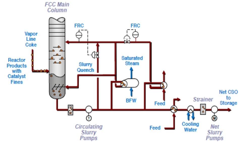
The best way to control the liquid rate is to use a total draw and meter and control the liquid returning to the column. Figure 1 shows a simplified sketch of an existing FCC unit. This unit has some complexity due to the decoupled heavy cycle oil (HCO) pumparound. Figure 2 shows some elements of a possible configuration that would allow tighter unit operation. Figure 2 includes:
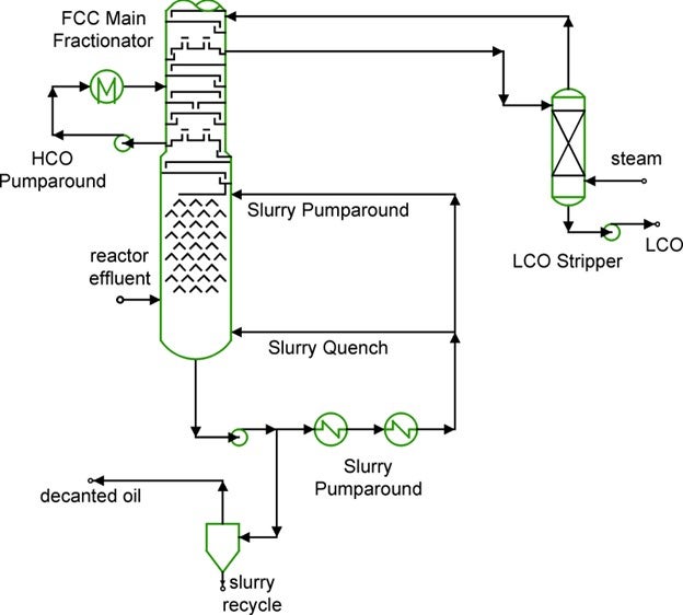
Figure 1 Base FCC Unit
The example shown is only part of the entire control system required. In this example, since no HCO product is made, any duty in the HCO pumparound shows up as HCO-slurry reflux liquid. The simple loops shown would be part of an entire unit multivariable optimizer. If no optimizer is present, other loops would be needed to make the system work correctly.
The purpose of a control system is to move disturbances from where they are more important to where they are less important. These control modifications do not make system disturbances go away. They shift it somewhere else. Typically, the disturbance is shifted to the product rates.
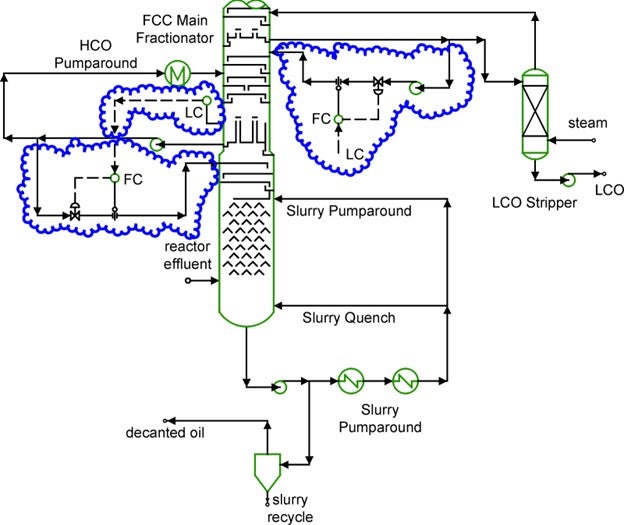
Figure 2 FCC Unit with total draws for improved LCO yield
The third approach is to add a decant oil stripper. Figure 3 shows this configuration. The stripper recovers LCO from the bottoms. The advantage of this configuration is that it has a minimal impact on the internal temperature profile inside the main fractionator. However, it does add vapor load to the main column and duty to the overhead condenser. Often the most significant issue is the increased duty on the main fractionator overhead.
The stripping can be a challenging service. If the slurry contains significant catalyst fines the stripper internals can easily plug and foul.
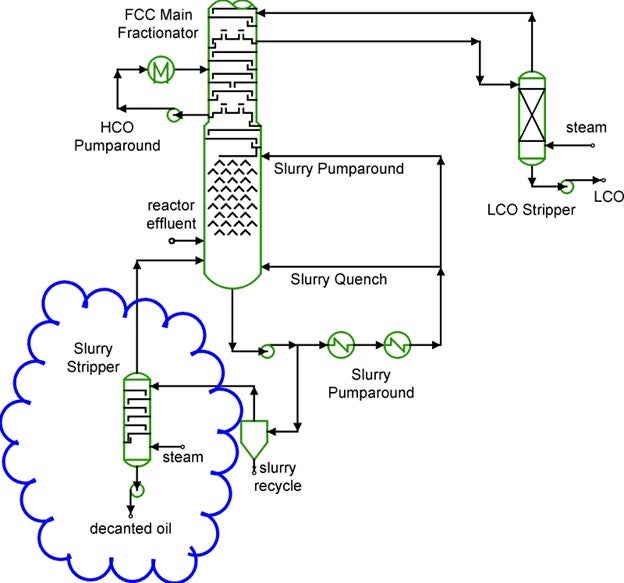
Figure 3 Slurry stripper to recover LCO
The options presented here are not the only possibilities. Nevertheless, the discussion covers the basic options and issues. Revamps must carefully balance yields, capacity, and product quality versus investment, reliability, and operating costs. Limits imposed by the unit configuration and equipment must be thoroughly understood to have a successful revamp that makes more LCO.
A team approach bringing in specialist resources with wide experience in practical applications at the very beginning of conceptual work will assure plants of success in FCC revamps.
MINAZ MAKHANIA (UOP)
Fouling in slurry circuit is commonly caused by coking. Three main variables affecting coking in the slurry circuit are: Composition, Residence time and Temperature.
Temperature: From experience, the rate of coke build-up increases greatly when the bottoms temperature is > 700F (370°C). It is recommended to maintain the bottom's temperature below 680°F (360°C) to be on the safe side. Often while processing highly paraffinic feedstock, 660°F (350°C) is a good starting point for MCB temperature and it can be optimized based on monitoring of heat transfer coefficients of the exchangers in the slurry circuit. Use quench a very low slurry API is required (e.g., for CBFS).
Minimize the level in the main column bottoms to reduce residence time. Typically, the minimum circulation rate required to prevent coking is 6 gpm/ft2 (14.67 m3/hr per m2) of column cross-sectional area but not less than 150% of the design feed rate for disc and donut trays to ensure trays stay wetted. UOP provides a hot bypass to help maintain the pump around rate without affecting main column heat balance.
More saturated slurries decompose at lower temperatures, increasing reactor temperature and catalyst activity to eliminate coking through this mechanism.
When running heavy feeds with a low matrix activity catalyst at low conversion, it is still possible to minimize coking with control of operation in the main column. As an initial guideline, UOP recommends that the light cycle oil draw rate be controlled to limit the slurry gravity at a minimum of -2°API or the slurry viscosity at a maximum of 25 cSt at 99°C.
Usually, slurry catalyst content does not directly cause coking problems. To prevent catalyst plugging or erosion in the exchangers, UOP recommends maintaining a maximum velocity of 8.0 ft/s (2.44 m/s) and a minimum velocity of 4.5 ft/s (1.37m/s) in the slurry exchanger tubes.
In general, the optimum velocity is 5.7 ft/s (1.75 m/s). Straight tube construction is recommended.
ALEC KLINGHOFFER (Coffeyville Resources)
Two main causes of FCC slurry circuit fouling:
Minimize coke formation.
Proper feed atomization.
Operate main fractionator bottoms temperature between 650 – 700°F.
Monitor asphaltenes in FCC feed.
Catalyst Particles
Set minimum flow rates through slurry circuit.
Monitor catalyst properties for signs of attrition.
SAEED ALALLOUSH (Saudi Aramco)
There are a couple of operating parameters that could improving the fouling rate in the slurry loop like slurry fluid velocity inside the slurry exchangers. Also, the design of the slurry exchangers can improve the fouling rate. Additives can also be used to minimize the fouling.
MICHAEL FEDERSPIEL (W. R. Grace & Co.)
Slurry exchanger fouling comes in several forms, which can be broken down into either organic or inorganic fouling. Inorganic fouling can be caused by corrosion products, precipitated metals, or catalyst particulates in the slurry circuit. Organic fouling, which is more common, can be caused by coke deposits or asphaltenes that have precipitated from the slurry.
Understanding and addressing the root causes of the different types of fouling can help minimize their impact on FCC operations. Using the correct metallurgy in the main fractionator and slurry circuit will significantly reduce corrosion. By closely monitoring antimony injection, a refiner can reduce the risk of antimony accumulation in the main fractionator.
By maintaining cyclone physical integrity and operating at proper cyclone inlet velocities, a refiner can reduce the contribution of catalyst particles to slurry fouling. It is also worthwhile to pay attention to catalyst and additive attrition index and particle size distribution as these can both impact losses to the main fractionator.
Time, temperature and composition of the slurry all contribute to coke formation and steps can be taken with each of these parameters to help minimize slurry fouling. Ensuring proximity of slurry exchangers and avoiding unnecessarily long slurry piping runs can reduce the amount of time slurry spends at elevated temperature. The temperature in the slurry circuit can be reduced using slurry quench. It is recommended to calculate and monitor the bubble point temperature of the slurry while using slurry quench as an indication of the slurry composition. Ensuring good distribution of the slurry circuit return to the main fractionator and maintaining a slurry pumparound rate such that the wash trays are always sufficiently wetted will also reduce the chances of coke formation. Finally, undercutting LCO into the slurry product will both reduce the temperature and lead to a directionally lighter slurry composition.
Asphaltene precipitation can occur when the asphaltene concentration increases (which can be due to feed type) or if the solubility of those asphaltenes is reduced. Asphaltenes are more soluble in highly aromatic environments, while the presence of more saturated compounds reduces this solubility and leads to fouling. Loss of conversion due to lower catalyst activity or reactor severity can lead to more saturated compounds in the slurry, so addressing loss of conversion is a solid strategy for reducing slurry fouling.
Grace published a thorough paper titled “Understanding and Minimizing FCC Slurry Exchanger Fouling” in Catalagram Number 101, Spring 2007. In it, the causes of the above types of fouling are discussed in more detail, along with mitigation strategies and design considerations. It can be found at this link: https://grace.com/catalysts-and-fuels/en-us/catalagram
References
1) Hunt, D., Minyard, B., Koebel, J., Davison Catalagram 101, Spring 2007, pp 30-36.
RAUL ROMERO (NALCO)
Comparison of current operating process variables on slurry/bottom P/A system with design ones should be a first step to assess operating gap and justify and understand any change. Some parameters like temperature profile through washing, sheds area and bottom systems, bottom residence time, P/A flowrates and heat exchanger velocities are key. Control stability of flows and temperature associated with above mentioned sections mitigate “coke spalling” situations leading to a sudden plugging of heat exchanger and pump filters. A thorough antifouling chemical program has demonstrated good success in preventing coking formation and catalyst deposit. This program should be preceded by a specific lab test program to identify the best solution for specific slurry properties.
TIFFANY CLARK (BASF)
BASF receives ECAT from about 200 FCC units worldwide. Of these, the ECAT activity ranges from 60-80, with approximately 75% of the units operating in the 70-76 activity range. The global average for 2017 was 72.5 and so far in 2018 the global average is 72.7.
In general, the average for the Americas has trended up year after year with Europe, Middle East and Asia staying relatively flat. The graph at the top left shows global ECAT annual average activities back to 2001 and the chart at the bottom shows the global range of these activities for the past 10 years.
Within this range, the bell curve varies a little from year to year as you can see here, with 74 being the most common in recent years.
Too low of a catalyst activity is relative to your individual refinery economics, configuration and feed composition, but it is very rare to see units operate below 65. Optimum catalyst activity should be determined with your LP or kinetic model using representative unit data.
Increasing conversion via operating severity versus catalyst activity can have different outcomes and again, is also dependent on your refinery economics. The window of conversion increase using operating severity is often limited by downstream process limitations and yields selectivity. For example, higher riser outlet temperature increases conversion but also promotes more thermal cracking that can result in higher dry gas and coke.
Catalyst reformulation should be considered if there have been significant or permanent changes in feed composition, feed rate, unit economics or if a new constraint has been reached at the FCC or an upstream or downstream unit. In many cases, interim catalyst formulation tweaks can achieve higher conversion and optimized selectivity, while meeting seasonal differences in product objectives.
ALEC KLINGHOFFER (Coffeyville Resources)
DEWEY STUART (Motiva Enterprises)
Catalyst activity ranges greatly depending on the type of unit, type of catalyst, unit constraints and type of feeds. Oversimplifying resid feed units would run MATs closer to 65 while non resid feed units would run greater than 72.
Catalyst activity is too low when the coke makes results in low regenerator bed temperatures. Once again, this changes significantly from unit to unit. The primary driver that dictates the Regenerator minimal temperature is if the unit is a full or partial combustion unit. Partial combustion units can be running at lower temperatures than full combustion units. In all units the transition between partial and full combustion should happen quickly as the transition can quickly lead to safety and/or environmental effects.
Primary driver on operating conditions versus reformulation of catalyst is around time. Short term or quick moving is managed with operating conditions while longer term forecast is addressed with reformulation.
BOB RILEY and MICHAEL FEDERSPIEL (W.R. Grace & Co.)
FCC catalyst activity is conventionally defined as 100 – (LCO, wt% + Bottoms, wt%), and is most often measured in microscale laboratory units. “Activity” refers to the propensity for the catalyst to upgrade heavier products into higher value, higher volume products. The absolute numbers measured will depend on several factors, including the specific testing unit and conditions, the choice of feedstock, and the quality of the catalyst being tested. There is no standard range or universally accepted testing equipment for FCC catalyst activity (although MAT and ACE® are popular designs), and each testing lab measures catalyst activity on a different scale, because of the reasons cited above.
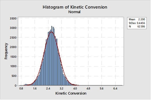
In Grace’s database, since 2014, the range of microactivity measured on individual samples has been between 48 and 85, with the overall average of 71.7 (Figure 1). This includes over 62,000 individual measurements, and the shape of the distribution is skewed right of normal because conversion reactions in the FCC are empirically approximated by 2nd order kinetics. To correct for this, one can look at Kinetic Conversion (defined as Conversion / 100-Conversion); this data is centered on a Kinetic Conversion of 2.6 over the same period, and much more closely resembles a normal distribution (Figure 2). It is important to note that the 48 to 85 Ecat activity range represents individual sample activity results; industry average Ecat activity typically ranges from low 80s too low to mid 60s.
Figure 1. Equilibrium catalyst activity as measured in Grace’s Ecat program since 2014.
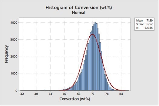
Figure 2. Kinetic (2nd order) conversion as measured in Grace’s Ecat program since 2014.
Catalyst activity requirements are a function of the objectives and constraints of any given FCC, which means that each unit likely requires a unique catalyst activity (or range of activity) to meet its goals. Catalyst activity is a function of the fresh catalyst composition, the catalyst addition/replacement rate, in-unit conditions (temperatures, residence times, and potential for thermal or hydrothermal deactivation), and the metals level and type on the FCC equilibrium catalyst.
Optimizing catalyst activity requires an intimate understanding of objectives and constraints; it is highly desirable to define the quantitative difference between today’s performance and the desired unit performance as opposed to the qualitative direction of desired shifts from current operation.
Symptoms of low catalyst activity can include low conversion, low regenerator temperatures, high cat to oils, and erratic regenerated slide valve delta P. These symptoms often represent the constraints present in low activity FCC operations. Feedstock, upstream units, and refinery flexibility will often dictate the operating window necessary for FCC catalyst activity.
In a typical VGO or resid operation, low catalyst activity leads to low regenerator temperatures and higher cat to oil ratio, often up to the limit of control as established by the stability of the slide valve differential pressure. In this scenario, the lower limit of catalyst activity is often set by circulation limits as manifested by low slide valve delta P. Higher cat to oil ratio is generally desirable for units pursuing maximum conversion. However, in some instances the higher cat to oil may not compensate for the lower catalytic activity which could result in lower conversion. Catalyst additions, reactor temperature, and even feed temperature can all be used as control handles to maintain an adequate differential pressure or enough level of conversion.
In contrast, a highly hydrotreated feed operation is likely to see low catalyst activity manifest as low regen dense bed temperatures, often near the point where combustion is not adequate to fully regenerate the catalyst. The lower activity limits in these operations are typically much higher than those in VGO service, and in this scenario, catalyst additions or catalyst reformulation are typically the best handles for managing regenerator temperature. Other methods, including torch oil injection, slurry recycle, fired air heater use, or even reduction in stripping steam, often cost more in lost products or in catalyst deactivation than they gain in unit operating stability. Routine use of these “other methods” for heat balance control should be viewed as an indicator of catalyst activity being too low.
Regarding reformulation vs. changes in operating conditions, catalyst reformulations are recommended to manage sustained changes in refinery operating requirements. Whether for increasing conversion, or managing virtually any new requirement on the FCC, the timing is a critical factor in the decision between the use of catalyst vs. the use of operating conditions. Examples of sustained changes that could merit a catalyst change include adjacent units nearing end of run conditions, sustained use of new feedstock, degradation of the mechanical condition of the FCC equipment, or market trends which require long term production of a modified yield slate. Because of the timing required to properly design, deploy, and turn over new FCC catalyst formulations, the main drivers for reformulation should be matched to the time scale of the unit’s ability to realize the benefits. For shorter term needs, it is often more desirable to consider changing operating conditions or using FCC additives to modify yield selectivities or manage short term refinery requirements. Operating conditions which can increase conversion include increased reactor temperature, reduced feed temperature, increased catalyst additions, reduced carbon on catalyst (partial burn units), and removal of low conversion feed components (slurry recycle, other low hydrogen content feeds, etc.).
SAEED ALALLOUSH (Saudi Aramco)
Catalyst
Reaction severity
Olefin content (with some limitation) by Increasing the naphtha cut from the fractionation column.
TIFFANY CLARK (BASF)
Refiners are optimizing their gasoline blend components to maximize high octane components. Alkylate and reformate yields are becoming increasingly important, as well as minimizing low octane component yields. The emergence of tight oil feeds has created an increase in low octane natural gasoline and LPG saturate production.
While some operational changes, such as raising the riser outlet temperatures, may seem like an obvious response to increase the gasoline octane, current economics in the U.S. penalize incremental production of dry gas due to its big discount to crude and other product slates; they limit octane gain via higher riser outlet temperature. Not only this, increase dry gas production limits Wet Gas Compressor throughput, which is a typical FCC constraint.
On the other hand, base catalyst reformulations that promote production of higher-octane gasoline and more LPG olefins production to increase the feed to the alkylation unit have become mainstream. Opportunistic usage of ZSM-5 and other butylene-increasing additives have become an important avenue for FCCs to increase the amount of high-octane gasoline blending components via alkylation. They also increase the octanes of the remaining gasoline as an added benefit.
MICHAEL TALMADGE (Johnson Matthey)
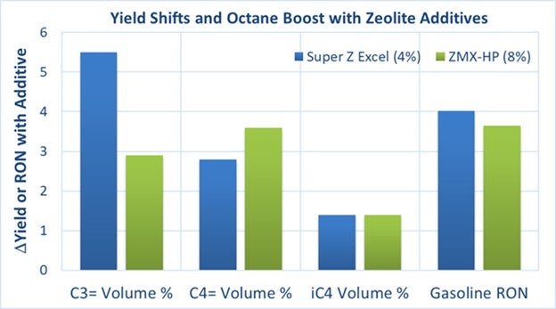
Many refiners are adding ZSM-5 and C4-selective additives to the FCC catalyst inventory to maximize FCC-derived gasoline octane. Gasoline octane is increased with these zeolite components from the following yield-shifting mechanisms in the FCC:
The figure below shows example yield shifts and RON increases for two of Johnson Matthey’s FCC additives, Super Z Excel (ZSM-5) and ZMX-HP (C4-selective).
KEN BRYDEN and BOB RILEY (W.R. Grace & Co.)
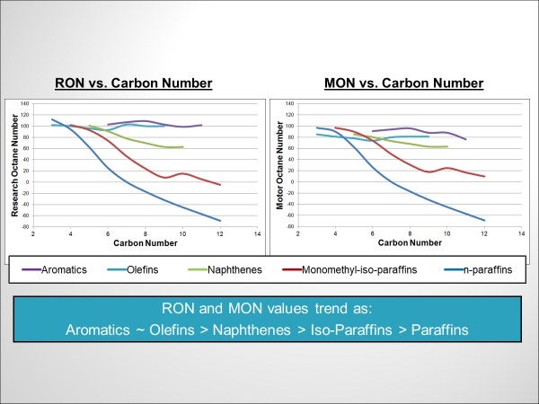
Octane is a relative measure of the knocking characteristics of a fuel in an internal combustion engine. Knocking is caused by auto-ignition of fuel ahead of the flame front. Different hydrocarbon molecules have different resistance to auto-ignition, related to their role in hydrogen peroxide formation under combustion conditions (Reference 1). Hence, gasoline octane is governed by the types and relative concentrations of the individual hydrocarbon molecules that comprise the fuel. Figure 1 presents octane trends by hydrocarbon type and carbon number based on data from API Research Project 45 (Reference 2). As seen in the graphs, lighter molecules have higher octane. RON and MON values trend by hydrocarbon type as follows:
Aromatics ~ Olefins > Naphthenes > Iso-Paraffins > Paraffins.
Also, for olefins and iso-paraffins, octane increases as the degree of branching increases. To increase gasoline octane, the composition of the molecular types in the stream must be changed. Changes that can be made specific to the FCC to produce higher refinery gasoline octane fall into two main categories: (A) changes inside the FCC unit that change the composition of the FCC gasoline, and (B) adjustments to FCC operation that improve overall refinery gasoline pool octane.
Figure 1- Octane Trends by Hydrocarbon Type
A) Changes Inside the FCC Unit
1) Gasoline Cutpoints
Changing the distillation range of gasoline from the FCC can influence octane. Butane is part of the light end of the gasoline and possesses a high-octane number. Increasing amounts of butane will increase RON. However, this must be balanced against vapor pressure considerations. For the heavy end, the effect of increasing gasoline endpoint on octane can vary. For aromatic gasolines, increasing end point will generally increase octane as more higher boiling point aromatic molecules are included in the gasoline. For other gasolines, the effect of endpoint on octane will vary with the feedstock to the unit, the conversion level and the catalyst. Detailed hydrocarbon analysis of FCC gasoline via gas chromatography and application of gasoline octane prediction models can be used to simulate how octane will change with gasoline endpoint (References 3 and 4).
2) Feedstock
The feedstock to the FCC will have a major effect on octane. Feedstock paraffins generally crack to form low octane gasoline range paraffins. Feed naphthenes crack to form high octane gasoline range aromatics and olefins. Aromatics with side chains present in the feed generally crack to form high octane gasoline range aromatics. As the feed becomes less paraffinic, octane increases. As a rule of thumb, a 0.2 number decrease in the UOP K factor of the feed will result in a 1 number increase in RON (Reference 5). Similarly, a 0.1 number increase in the ratio of naphthenic to paraffinic carbons (Cn/Cp) in the feed will generally result in a 1 number RON increase (Reference 6).
3) Operating Variables
Increasing riser outlet temperature will increase RON by increasing the number of olefins in the gasoline. As a rule of thumb, at a base RON of 90, an 18°F increase in riser temperature will result in a 1 number increase in RON (Reference 7). The octane gains with increasing riser outlet temperature will diminish as reactor temperature increases. More precise values can be determined by cat cracker operators through observations made on their own units.
Increasing conversion will increase octane. As conversion increases, cracked products increase, which means that the number of olefins and aromatics in the gasoline increases. As a rule of thumb, a 10 LV% increase in conversion will result in a 1 number increase in RON at constant riser outlet temperature.
Decreasing hydrocarbon partial pressure will increase FCC gasoline octane. Gasoline olefin content increases when the rate of bi-molecular hydrogen transfer reactions drops – which happens as hydrocarbon partial pressure drops.
4) Catalyst and Additives
The molecular composition of FCC gasoline is governed by the relative rates of cracking and hydrogen transfer reactions. Lowering zeolite unit cell size will lower hydrogen transfer and increase gasoline range olefins and thus increase octane. Increasing matrix content of the catalyst will help to crack side chains off aromatic cores and increase octane by increasing gasoline range aromatics. Dual-zeolite catalysts that incorporate both faujasite and pentasil type zeolites will lead to increased rates of isomerization and result in higher octane from the greater amount of branched hydrocarbons. ZSM-5 based additives and butylene selective additives can also be used to increase octane. These additives can increase isomerization reactions. Also, by cracking some gasoline range olefins to LPG olefins, they concentrate aromatics in the FCC gasoline, resulting in increased octane.
B) FCC Adjustments to Improve Overall Refinery Gasoline Pool Octane
1) Increasing alkylate production
With a typical RON of 95+, alkylate is one of the highest-octane blend streams in the gasoline blending pool. For refineries with alkylation capacity, FCC adjustments that increase the amount of LPG olefins used as alkylation feedstock will increase alkylate production and refinery gasoline pool octane. LPG olefins from the FCC can be increased by adjustments to reactor conditions, base catalyst, and use of ZSM-5 based additives. For units desiring a higher ratio of butylene to propylene in their LPG, butylene selective additives can be used instead of conventional ZSM-5 type additives. Variables that affect LPG olefin production in the FCC have been covered in detail in previous AFPM Q&A sessions (References 8, 9).
2) Reducing FCC gasoline hydrotreating severity
Refiners report losses between 1 and 5 numbers of octane when FCC gasoline is hydrotreated to remove sulfur. Hydrotreater severity can be lowered when the FCC gasoline contains less sulfur. Lower FCC gasoline sulfur can be achieved through use of gasoline sulfur reducing catalysts and additives that convert gasoline range sulfur to hydrogen sulfide. A detailed discussion of preserving octane with gasoline desulfurization technology can be found in Reference 10.
In summary, there are many ways FCC operations can be adjusted to increase octane. Inside the FCC unit, octane can be increased through feedstock selection, choice of operating conditions, tuning of base catalyst properties, and use of specialty additives. Outside of the FCC, the amount of alkylation feed derived from the FCCU can be increased through careful FCC catalyst and additive selection, and octane loss during FCC gasoline hydrotreating can be reduced by lowering FCC gasoline sulfur through use of gasoline sulfur reducing catalysts and additives.
As always in FCC, changes to influence one variable (octane), will result in changes to other FCC unit yield objectives. Refiners should work closely with their catalyst supplier to understand the options available to increase octane and how to balance these with other yield objectives. Grace has a wide portfolio of catalyst and additive solutions and would be happy to engage with refiners to discuss options to increase gasoline octane.
References
1) Westbrook, C.K., "Chemical Kinetics of Hydrocarbon Ignition in Practical Combustion Systems," Proceedings of the Combustion Institute, Volume 28 (2000), pp. 1563–1577.
2) Knocking characteristics of pure hydrocarbons, Developed under American Petroleum Institute Research Project 45, Special Technical Publication No. 225; American Society for Testing and
Materials: West Conshohocken, PA, 1958.
3) Cotterman, R.L., Plumlee, K.W., “Effects of Gasoline Composition on Octane Number,” Proceedings of the Symposium of the Division of Petroleum Chemistry, American Chemical Society Meeting, Miami Beach, Florida, 1989, pp. 165-171.
4) Haas, A., McElhiney, G., Ginzel, W., Buchsbaum, A., “Gasoline Quality- The Measurement of Compositions and Calculation of Octanes,” Petrochem/Hydrocarbon Technol. 1990, 43, 21-26.
5) Magee, J.S., Ritter, R.E., Wallace, D.N., and Blazek, J.J, "How Cat-Cracker Feed Composition Affects Catalyst Octane Performance AM-80-48" 1980 NPRA Annual Meeting, New Orleans, Louisiana.
6) Andreasson, H.U. and Upson, L.L., "Four Main FCC Factors Affect Octane," Oil and Gas Journal, August 5, 1985. p. 91.
7) Chapter 6, "FCC Operation," in Grace Davison Guide to Fluid Catalytic Cracking
8) Question 101, FCC Q&A Session, AFPM Q&A and Technology Forum, October 2014.
9) Question 10, Process Q&A Session, AFPM Cat Cracker Seminar August 2016.
10) Cheng, G., "Preserving Octane for a Tier 3 Gasoline Market CAT-16-23," 2016 AFPM Cat Cracker Seminar.
MATTHEW WOJTOWICZ (UOP)
If a potential future scenario occurs, where specifications require production of higher-octane gasoline, refiners in the United States have several options to enable production of greater amounts of higher-octane gasoline. Each refinery would require a unique solution, depending upon the existing configuration, future target gasoline specifications and future target gasoline production rates – the extent of any modifications would also depend upon the existing refinery complexity and process unit capabilities. UOP has studied ways to increase gasoline RON for our customers with different types of refineries, and lower complexity refineries would likely require significant investment to enable higher octane gasoline production compared with more complex refineries. Production of 95+ RON gasoline is being achieved throughout most of the world. The United States (US) is one of the few countries in the world that does not currently consume gasoline with a RON of 95 or higher.
Solutions for improving octane:
CCR Reformer
Increase existing CCR Reformer severity to produce higher octane reformate for blending (~101* RON could potentially be achieved based on typical designs). This will lower yield but will enable refiners to utilize latent octane capability in existing units. With the introduction of ethanol (120+ RON) into the US gasoline blend, refiners have dialed back reforming severity and reformate octane.
Revamp an existing CCR reformer to achieve ~105* RON.
Add a CCR reformer if a reformer does not currently exist in the refinery.
SR Reformer
Increase existing SR reformer severity to produce higher octane reformate for blending (~95* RON could potentially be achieved based on typical designs). This will lower yield but will enable refiners to utilize latent octane capability in existing units.
Revamp an existing SR reformer to achieve ~101* RON.
Light Naphtha Isomerization
Add an isomerization unit if one does not currently exist – this will increase the octane of the light naphtha (~85* RON could be achieved).
Add a deisohexanizer to an existing isomerization unit – this will further increase the octane of the light naphtha (~88* RON could be achieved).
Add deisohexanizer and a deisopentanizer to an existing isomerization unit to achieve ~91* RON.
FCC
Increasing FCC operating severity (increased conversion) in conjunction with the addition of ZSM-5 additive will increase the light olefin yield (propylene, butylenes and amylenes), but at the expense of overall FCC naphtha production. These lighter olefins can be sent to an alkylation unit, where the increased alkylate production, along with its inherently higher RON, will help offset the loss of naphtha production from the FCC. The remaining FCC naphtha will also experience an increase in the RON.
As you increase the severity of operation in the FCC unit for higher light olefin production the following will happen: 1) more naphtha range olefins are converted to light olefins (propylene, butylenes and amylenes); 2) aromatics are concentrated in the FCC naphtha, thereby increasing the overall RON.
Alkylation
Additional alkylate with ~95 RON can be purchased.
Increase alkylation capacity to produce additional alkylate. Increasing FCC operating severity as discussed above increases propylene and butylenes that can be converted to alkylate. The ultimate potential capacity of the alkylation unit is generally limited by the propylene and butylenes that can be produced by the FCC unit.
In the US, this could be overcome by leveraging low cost C4’s (from the natural gas fields) and by adding a butane dehydrogenation unit. Increased alkylation capacity is enabled through production of additional butylenes from the low cost C4’s.
*Typical RON representations. These may vary for a specific refiner.