Registration
Session Start End
-
CARLSON (Criterion Catalysts & Technologies)
There were a number of questions this year that requested information about how to effectively utilize low-cost hydrogen to increase refinery volume yields. To fully explore this theme, a Principles & Practices session will follow the Q&A and will cover the Strategies for Leveraging Low-Cost Hydrogen, including:
• Low-capital expense options (near-term),
• Product volume gain options,
• Optimizing H2 usage,
• Technology-based options for large capital projects (mid-long term), and
• Upgrading via H2-addition instead of carbon-rejection
Currently, as natural gas production hits unprecedented highs, we are fortunate that the cost of both natural gas fuel and hydrogen production has dropped to the lowest levels in the past decade. This cost-savings offers the opportunity to increase our utilization of low-cost hydrogen with the benefit of both higher liquid volume yields, as well as the capability of increasing the production of higher value products. Combined with the process efficiencies and capabilities gained in our facilities during the clean fuel's implementation, this current global advantage enables us to improve facility margins.
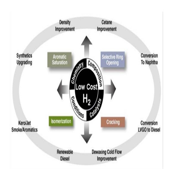
The chemistry available to us includes sulfur and nitrogen removal, aromatic saturation, selective ring opening, hydrocracking/conversion, and isomerization. With the implementation of clean fuels projects and continued catalyst development, many refiners are in the position of moving towards increased hydrogen uptake and reaping its benefits with minimal further investment.
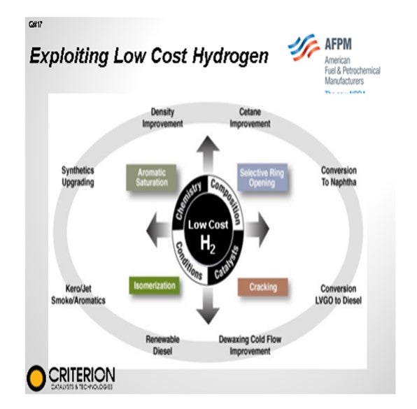
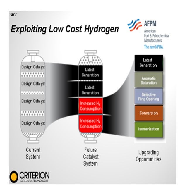
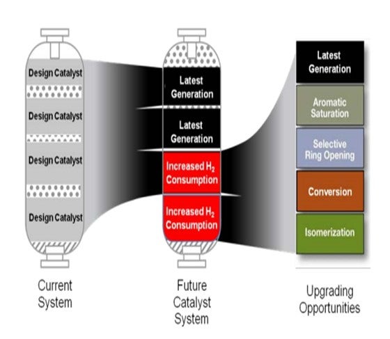
We have all spent a lot of time and energy increasing our hydroprocessing assets’ capabilities as we drive for clean fuels production. As we have done that development, advances in catalyst technology continue and have resulted in many “original” hydroprocessing unit designs now having additional underutilized capabilities. Many of these designs can be exploited with drop-in solutions during a catalyst changeout. By utilizing advances in catalyst capability, we can effectively provide additional reactor volume to provide further hydrogen utilization upgrades and extend days-on-stream or further increase unit capability by the application of additional upgrades utilizing the following technologies.
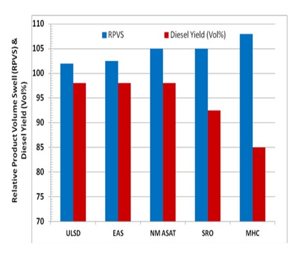
• Aromatic saturation can further enable density upgrades, smoke-point improvements, feed difficulty capability, and FCC yield gains.
• Selective ring opening will further improve density and volume swell while improving diesel cetane.
• Conversion via hydrocracking (distillate, VGO, resid) can minimize lower value fuels while increasing product quality and margins.
• Isomerization will improve distillate cold flow properties
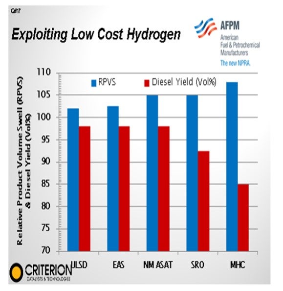
This graph highlights the impact of volume swell in distillate yield when applying some of the various technologies available. As you can see, the ultimate technology selection we choose for our own sites will really be dependent on the yield in volume gain for our facilities. We can really push the volume gain going to mild hydrocracking; however, we will start losing distillate selectivity. So, there is a wide range of options to evaluate when determining what is best for our facilities.
Beyond the gains we may be able to achieve with a drop-in solution, further capabilities can often be realized by combining these options with additional process improvements that can fit within a normal turnaround window. Improving reactor internals and instrumentation/control, as well as ensuring that the recovery and fractionation sections are in optimal condition, can all help push the level of performance while maintaining operational reliability and flexibility.
BODOLUS (CVR Energy)
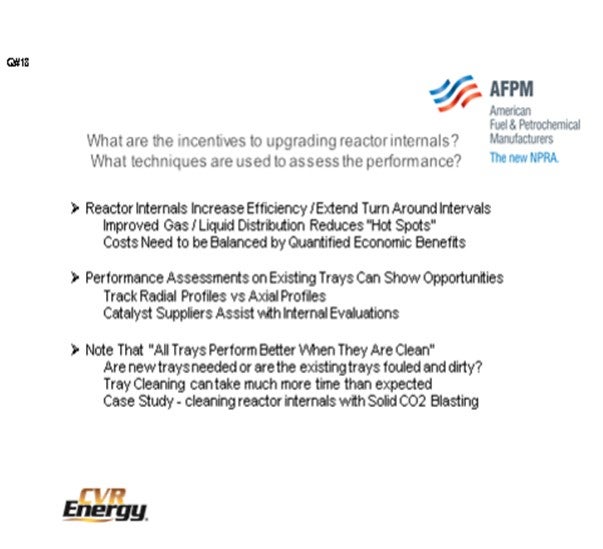
Reactor internals have many benefits for you including increasing efficiency, extending turnaround intervals by improving gas to liquid distribution, and reducing hot spots. However, the tray hardware is often very expensive and difficult to install, so the costs need to be balanced by qualified economic benefits.
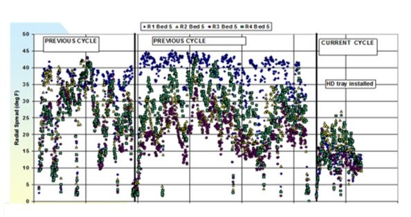
As far as the performance assessment, unit engineers can use techniques to track radial profiles versus axial profiles. There are many other examples of pulse technology in the Answer Book. I know Kevin included good examples in his response, in addition to tracer studies. Also, outside vendors will help you prove that you need new trays and provide justification for them. One issue I have come across in the last 10 or so years is having new generation trays that show a significant decline in performance in use. You cannot really justify a whole new set of trays, primarily due to the fact that these trays have gotten fouled out and dirty. Also, it is often very, very, very difficult to clean them during the short window of a turnaround outage.
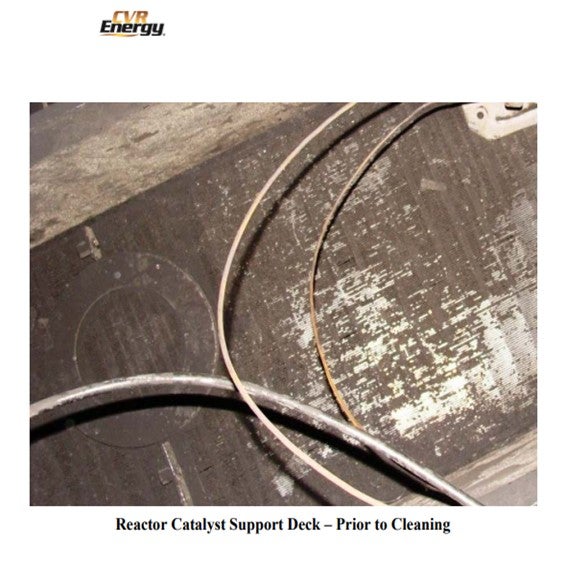
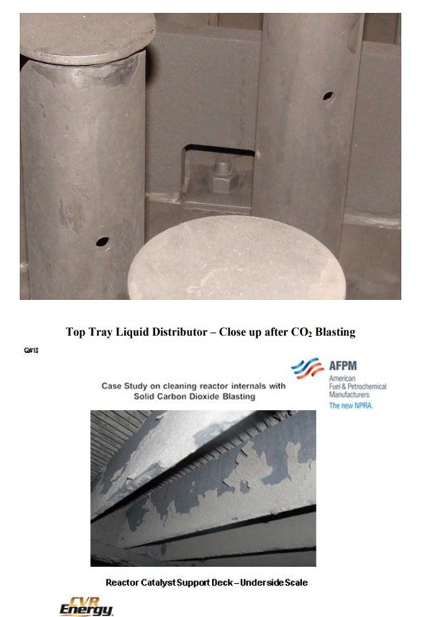
I have a case study with a couple of photos that are worth a thousand words. The case study was on solid CO2 (carbon dioxide) blasting. Shown are the innards of a typical hydrotreating reactor. This is the catalyst support bed. The catalyst pellets get embedded in that Johnson screen down at the bottom. The wedge wire is very difficult to clean. It could take a guy a couple hours to clean this.
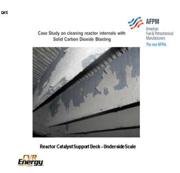
The next photo shows you underneath the hood and the tray support. As I mentioned a little earlier, you will find iron sulfide scale there. And if you look up into the nooks and crannies, you will see all of these sheet-like deposits that can break off later. If you do not clean them out, they might break off later and cause you liabilities of pressure drop in your bed and maldistribution of flow.
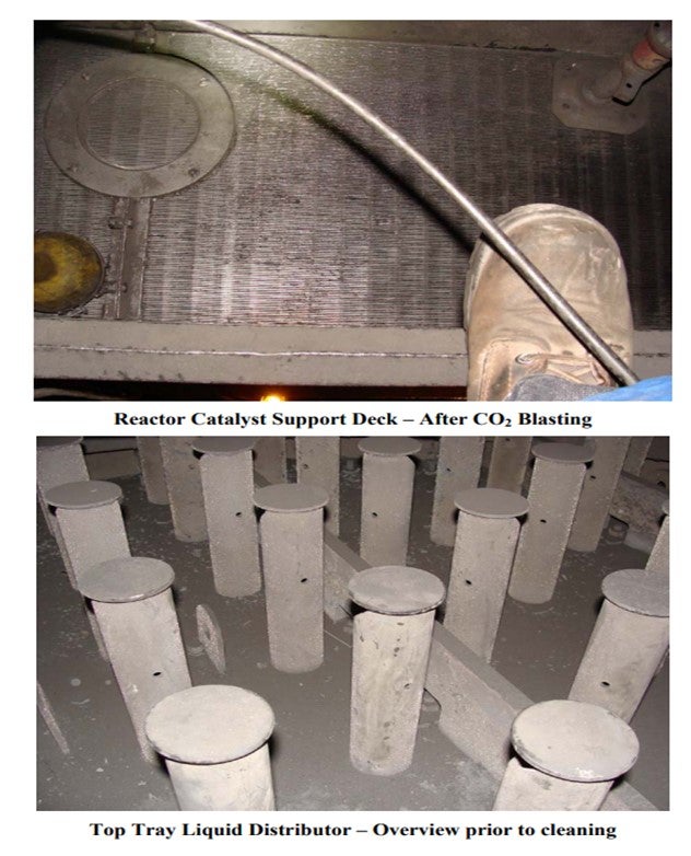
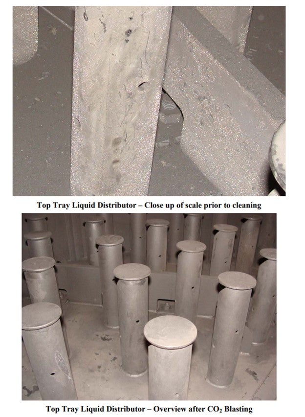
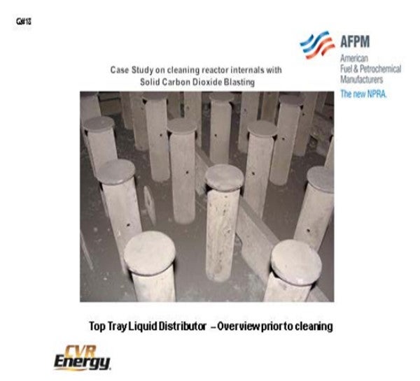
The next slide shows the liquid distributor. It accumulates debris on the deck of these things. And if you look closely, you can see the iron sulfide scale all over the place. Historically, I have tried a lot of different techniques; hydroblasting done in with Tanner K hydroblasters. Two or three days later, the turnaround guys are all over you because you are still cleaning up the mess.
The next slide shows some of our success. From a distance, it might not look like it, but the wedge wire here is 80% to 95% better than it was when we started. If we zoom in on the picture, you can see the lights underneath. This picture shows that same distributor tray after it was been cleaned up with solid CO2 blasting, which is good because the CO2 just sublimes away. There is nothing to brush up or clean up, with the exception of just the dust that has formed.
This slide shows that same situation. This solid CO2 blasting gets into all of the little nooks and crannies and cleans things out. I want to tell you, it was a long shift. These tray pictures were taken after one 16-hour shift inside the reactor, which would have normally taken multiple shifts to do this level of cleaning with mechanical hand tools and vacuums.

ROBERTSON (AFPM)
That is the response from the panel. Kevin and James have responses in the Answer Book.
PUI-NANG LIN (Flint Hill Resources, LP)
Very impressive pictures on the CO2 blasting performance! Are you doing this blasting under inert atmosphere, or do you have a concern about the confined space situation with CO2?
BODOLUS (CVR Energy)
This reactor was turned over to air, but the CO2 blasters do have the same inert atmosphere headgear. They have all of the requirements of an inert atmosphere entry. Even though the reactor is under air or under inert, it does qualify for all of the inert entry procedures. So yes, they operate as if the unit was inert.
PUI-NANG LIN (Flint Hill Resources, LP)
Do you use a specialized company to do this, or did your company personnel do this blasting in-house?
BODOLUS (CVR Energy)
It is a specialized skill that requires specific equipment, as I understand, and there are a number of folks who offer this service. I do not want to advertise any of them, so just contact someone who does solid CO2 blasting and can demonstrate it with a track record at refineries. We have also used convective section tubes in heaters, and the results are amazing.
CARLSON (Criterion Catalysts & Technologies)
There were a number of questions this year requesting information to how we can effectively utilize low-cost hydrogen to increase our refinery volume yields. To fully explore this theme a Principles & Practices session will follow the Q&A covering the strategies for leveraging low-cost hydrogen including:
• low-capital expense options (near-term) including product volume gain options and optimizing H2 usage,
• technology-based options for large capital projects (mid-long-term), and
• upgrading via H2-addition instead of carbon-rejection.
We are currently fortunate that with natural gas production hitting unprecedented highs that the cost of both natural gas fuel and hydrogen production have dropped to the lowest levels in the past decade. This offers the opportunity to increase our utilization of low cost hydrogen with the benefit of both higher liquid volume yields, as well as the capability to increase the production of higher value products. Combined with the process efficiencies and capabilities gained in our facilities during the clean fuels implementation, this current global advantage enables us to improve facility margins. According to a recent Hart Energy report, U.S. refiners have a greater than $6 per barrel advantage over Asian competitors.
The chemistry available to us is sulfur and nitrogen removal, aromatic saturation, selective ring opening, hydrocracking/conversion, and isomerization. With the implementation of clean fuels projects and continued catalyst development, many are in the position to move towards increased hydrogen uptake and its benefits with minimal further investment.
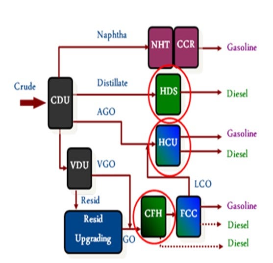
Looking at the existing applications in our refineries that can potentially increase hydrogen utilization we have a wide range of upgrade potential across the boiling range. To facilitate an accelerated implementation of this current opportunity we would first focus on what can we do with our existing distillate and heavy gas oil units to maximize volume gain and product quality benefits with “drop-in” solutions.
Development and advances in catalyst technology continue following the significant R&D efforts employed during the global clean fuel's initiatives. This has resulted in many “original” hydroprocessing unit designs now having additional underutilized capabilities, many of which can be exploited with drop-in solutions during a catalyst change out. By utilizing advances in catalyst capability, we can effectively provide additional reactor volume for further hydrogen utilization upgrades and the extension of days onstream. Examples of the benefits available through catalyst advances are described below.
• Aromatic saturation can further enable density upgrades, smoke point improvements, feed difficulty capability, and FCC yield gains
• Selective ring opening will further improve density and volume swell while improving diesel cetane.
• Conversion via hydrocracking (distillate, VGO, resid) can minimize lower value fuels while increasing product quality and margins.
• Isomerization will improve distillate cold flow properties.
Beyond the gains we may be able to achieve with a drop-in solution, further capabilities can often be realized by combining these options with further process improvements that can fit within a normal turnaround window. Improving reactor internals and instrumentation/control and ensuring the recovery and fractionation sections are in optimal conditions can enable pushing the level of performance while maintaining operational reliability and flexibility.
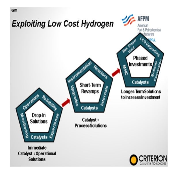
The assets and economic situation of each refinery are unique, but new projects large and small can enable survival and even thriving in difficult economic times by including reliable and flexible technology selection. Taking advantage of the current low hydrogen and fuel costs to increase and upgrade our transportation fuels can be done with a combined effort of utilizing immediately available drop-in solutions, short-term revamps that increase capabilities of assets, and longer-term projects for taking advantage of global market fluctuations.
Today, advances in hydroprocessing technologies and reactor design are providing refiners the ability to meet these challenges, enabling reliable, successful operations into tomorrow.
STEFANO MELIS (Albemarle Corporation)
Hydrogen addition is one of best ways to increase refinery volume gain considering the current low cost for hydrogen. The easiest solution is to resort to more active hydrogenation catalyst in distillate or VGO hydrotreaters.
Regarding ULSD units, application of very active hydrogenation catalyst is recommended only if unit pressure is on the high side. At low pressure, additional aromatic saturation is often limited by thermodynamic equilibrium so that application of active hydrogenation catalyst is much less effective and may even reduce cycle length. In these units it is preferable to operate with the most active desulfurization catalyst. To maximize hydrogen uptake, the unit is operated close to its maximum aromatic saturation point right from start-up,
allowing sulfur giveaway. Operating temperature is kept constant until the S (sulfur) specification is hit and then progressively increased to compensate for catalyst aging. Such a strategy provides an average density gain by 0.5 g/l (grams per liter) to 1.0 g/l over the course of the cycle.
At higher pressure levels (i.e., hydrogen partial pressure at reactor outlet above 600 psi to 700 psi) use of catalyst with high hydrogenation power may lead to a significant volume gain of up to 5 g/l depending on unit specific conditions. However, application is not always straightforward. Extremely active hydrogenation catalysts have a tendency to coke due to local hydrogen deficiency, at the top of the reactor, for instance. In general, an optimal catalyst design technology (such as Albemarle’s STAX® technology) is recommended in which catalysts are sequenced according to the reaction chemistry of a particular location in the reactor. Very active hydrogenation catalysts are placed where they are most effective.
Evaluation of hydrogen addition in VGO hydrotreaters is more complex since economics is related to the modification in the yield structure of the downstream FCC unit. Also for this case, hydrogen addition can be achieved through dedicated catalytic solution coupled with dedicated operating strategies. Once again, if hydrogen pressure of the unit is on the high side, there are more possibilities to improve the density gain. In general, better density gain in the VGO hydrotreater corresponds to higher conversion and better product quality (with particular reference to light cycle oil) in the FCC unit. However, coke formation in the FCC tends to decrease and this might become limiting.
Another approach to improve the density of the VGO hydrotreater (particularly those operating at high pressure) consists in the increase of severity, with particular reference to the operating temperature. In this way, the main result is the increase in the conversion to middle distillate which is anyway balanced by a reduction in cycle length. Such severity increase also leads to a decrease of bottoms density (with related modifications in FCC yield structure) and always to an increase in hydrogen consumption. Of course, a reduction of bottoms throughput is consequential.
One way to improve refinery volume gain is to modify the operation of the conversion units; for example, shifting some feed from coking/visbreaking units to hydrocrackers (i.e., cutting the VGO deeper). Such an approach may be favored by the low hydrogen cost; but since it affects refinery yield structure, other market specific factors may overrule
BODOLUS (CVR Energy)
The primary incentive is catalyst life and the ability to meet turnaround intervals. Gas and liquid distribution improvement results in increased catalyst performance and potentially longer catalyst life. Reactor internal upgrades may consist of quench decks, mixing chambers, and improved liquid distributor trays. Reactor internals are expensive and can take considerable effort to install. Costs can be readily defined up front, but “hard dollar” economic benefits are more difficult to quantify.
Assessing performance can be done on temperature distribution within the bed where the ratio of radial distribution (across a bed level) is tracked with axial distribution (bed temperatures at increasing bed depth). The technique requires the existence of multiple thermocouples in the bed, which is typically an upgrade that is done when internals are changed out.. A typical guideline for good distribution within a reactor is for the radial differential temperature (DT) to be 10% to 15% of the axial DT. A radial-to-axial profile in excess of 20% may indicate inefficient distribution or bed channeling. Tracking the radial-to-axial profile with reactor rate will help define turn-down limits or indicate that better technology is needed for the particular operating scheme being used.
As reactor internals become mechanically complicated, maintaining cleanliness becomes important for continued performance. Modern internals provide efficient gas and liquid distribution in a minimum space, but cleaning them to maintain performance on subsequent outages is difficult and time consuming. Under inert conditions, manpower inside the reactor is limited and detailed inspections for cleanliness often depend on video cameras that only show what they are pointed at. If the reactor is exposed to normal atmospheric conditions of oxygen and moisture, it can cause normally adherent iron sulfide scale to curl and flake-off. The longer the reactor is exposed to atmospheric conditions, the higher the prospects that the initially adherent scale will curl and flake.
Pre-cleaning the reactor with chemicals at the start of the turnaround can be effective in hydrocarbon deposit removal, but the inorganic scale on the reactor internals needs mechanical force for removal. Cleaning with manual labor is highly dependent on the workforce and accessibility. Hydro blasting has been used with some success, but it has a lot of potential drawbacks. Solid carbon dioxide blasting has shown excellent results as it is very effective in dislodging scale and deposits from traditionally hard to reach places.
CARLSON (Criterion Catalysts & Technologies)
Catalytic hydroprocessing technology has been applied for many years in the upgrading of refinery hydroprocessing streams. The reactions are typically carried out in co-current adiabatic fixed-bed reactors.
The performance of such reactors is determined by the loaded catalyst and also, to a large extent, by the design of its internals. In the last 15 years, there has been considerable attention for the issue of maldistribution in vapor/liquid hydroprocessing applications: insufficient distribution of gas and liquid inside the reactor leads to underutilization of the catalyst and local hot spot formation. This has detrimental effects on catalyst cycle length, product quality, unit reliability and process safety. In a number of articles published, successful revamps have been presented, showing how installation of state-of-the-art internals had positive effects on these parameters, as well as provide an economic way to debottleneck units for refiners everywhere in the world.
When considering upgrading reactor internals in an existing hydroprocessing application, the economic gains can be realized from a number of operational capability improvements:
• Increased operational cycle life, reducing both long-term maintenance and catalyst costs,
• Improved product qualities and yields,
• Reduced capital expenditures for revamps to meet process improvement requirements, and
• Increased safety and reliably
When reviewing the benefits, the first step is to understand what operational limitations currently constrain the overall economic value of the unit’s performance, such as
• A pressure drop resulting in early unit shutdowns,
• A high radial delta T resulting in a limited EOR operating temperature,
• Unit activity limitations resulting in either lower-than-desired feed rates or shorter-than-desired operation cycles, and/or
• An inability to meet product specifications with current performance.
In many hydroprocessing units, utilizing upgraded internals can relieve these constraints.
via:
• Removal of foulants and contaminants with a scale catching or filter tray,
• Improved catalyst utilization due to a homogenous distribution with a high dispersion tray,
• Thermal uniformity and quench injection with an ultra-flat quench mixer, and/or
• Increased active catalyst loading via reduced need for hold down material, quench zone “straight wall”, and bottoms inerts.
In one of many examples, the figure below highlights the improvement in flow distribution in a hydrocracker as indicated by the reduction in radial temperature deviations. This improvement had the benefit of opening the operating window of the unit and extending the cycle life, as well as increasing performance due to improved catalyst utilization.
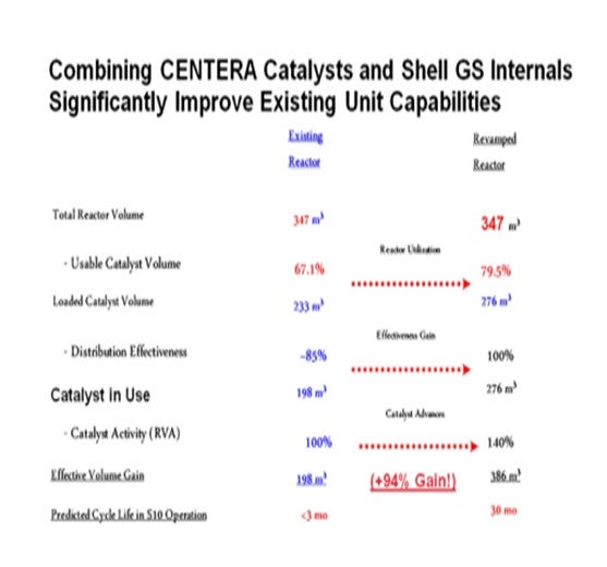
As many existing hydroprocessing units can take advantage of improved internals, combining advanced reactor internals with recent catalyst developments can significantly increase process capability. In the example summarized below, and recently presented at another industry conference, this approach was used to revamp an LSD unit into ULSD service while minimizing the cost and complexity of the required revamp.
Diagnosing existing operations can be accomplished by a number of approaches.
• Day-to-day radial temperature spreads
• Evaluation of radial to axial temperature spread ratios
• Kinetic response test
• Radio-Isotope tracer studies
• Pulse test: transient temperature change response study
Often current performance has been preliminarily evaluated by the review of the day-to-day temperature reading. While this can indicate potential issues in the reactor, a snapshot of temperature deviations does not provide sufficient information to accurately judge performance as many things can lead to these observations such as catalyst fouling or loading problems, as well as in some sections of reactor beds poor operation may masked due to low axial temperature changes. A pulse test in which a small temperature change is introduced into the reactor sections is a very easy way to qualitatively diagnose potential distribution, fouling, or mixing issues in the reactor beds. In addition, Shell Global Solutions has a detailed analytical approach that utilized pulse test data to provide a quantitative evaluation of current performance. and providing a measurement of potential performance.
ESTEBAN (Suncor Energy, Inc.)
The major economic incentives to justify upgrading reactor internals are increased catalyst utilization and minimization of hot spots resulting in increased catalyst life cycles (unit availability), increased capability to process more feed or more difficult feed, improved product quality, and in some cases improved yields. The performance of reactor internals can play a huge role in the overall performance of a catalyst system because catalyst life cycles are optimized by proper reactor flow distribution, good mixing with quench streams, and minimization of reactor weighted average bed temperatures (WABT). In cases where the metallurgical design temperature limitations of the reactor and heat exchange equipment determine end of a catalyst cycle, minimizing hot spots can extend catalyst life cycles by permitting operation to higher maximum WABTs. When product quality dictates catalyst life cycles, the improvement in product quality due to improved flow distribution can also extend cycle life by permitting operation to higher maximum WABTs. Unfortunately, in some cases catalyst life cycles are limited by overall reactor pressure drop which can reduce unit feed rates to less than desirable levels and/or heat transfer equipment limitations that will not permit on-specification operation at higher rates, both, impacting overall refinery throughput. In these cases high performance reactor internals have the potential to improve catalyst life cycle performance extending run lengths which relates to both reduced catalyst costs and increased refinery throughput. In addition to improved unit availability, upgrades to reactor internals can provide improvements in product yields, which are more evident operating at high WABT at the end of cycle or high conversion rate when considering modifications to hydrocracking units.
The two key benefits to high performance internals are even distribution and improved quench mixing. Improvements in reactor distribution and quench mixing result in a more even use and deactivation of catalyst lowering the severity required to meet product specifications. As well these improvements can reduce the potential for formation of pressure drop depending on the contributing causes for excessive pressure drop and assuming proper catalyst loading. In some cases the current performance of reactor internals can be implied by comparing the average final reactor bed outlet temperature to the combined temperature of the stream in the piping downstream. A large difference in these values can indicate poor distribution.
In order to provide a better measure of improvements in distribution and quench mixing, one simple method using existing equipment Suncor Energy, Inc. has employed to evaluate reactor internals performance is the statistical analysis of data provided from temperature pulses. The method of analysis is based on the principle that if the distribution in a catalyst bed were perfect, a temperature pulse initiated at the top of the bed would travel down and reach each point in any horizontal plane simultaneously. In addition, if the uniformity of catalyst activity and catalyst loading were perfect, the temperature difference between each point in any horizontal plane and the bed inlet temperature would be the same. This concept of perfect distribution is used to evaluate the performance of the old internals versus the new internals, as well as provide information regarding the gap between perfect distribution and actual performance to determine the potential benefits of upgrading internals. The following describes the test method previously used by Suncor Energy, Inc. sites:
Test Method: During a test run or several runs, the temperature at the inlet of each bed is reduced by approximately 5°F and then increased back to its original setting. Data from every available bed temperature indication (TI) is then collected. Using all available temperature data, three variables are calculated for each temperature signal.
1. Delay time: The amount of time that it takes for a temperature pulse to reach a TI.
2. ∆T: The temperature difference between each TI and the average bed inlet temperature.
3. Gain: The derivative of each TI with respect to the average bed inlet temperature. For example, if the bed inlet temperature was increased by 1°F and the TI increased by 0.5°F as a result, the gain would be 0.5.
With perfect distribution, a plot of ∆T versus delay time would show a near-linear correlation with a coefficient of determination, R2, equal to one. The R2 of the ∆T versus delay time correlation for each bed is used to determine the nearness to perfect distribution.
Using the previously described method several Suncor sites have been able to determine the performance improvements resulting from tray modifications and have been able to achieve distribution results in the 0.9 to 0.95 range. The following figure displays the improvements from a project in our Edmonton Refinery in 2005.
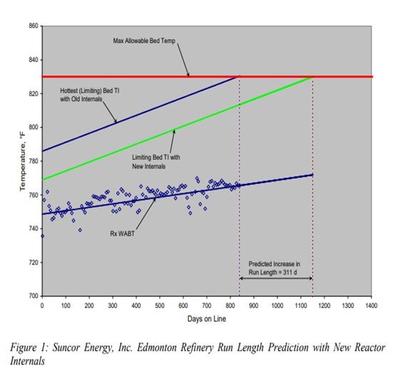
In addition to the benefits mentioned above, the installation of new trays in hydroprocessing reactor vessels can provide additional reactor volume for catalyst and provide ease for maintenance personnel, increasing cycle length and reducing shutdown timing respectively.
SUBHASH SINGHAL (Kuwait National Petroleum Company)
Increased catalyst cycle length, more selective yield pattern, and reduced temperature mal distribution are some of incentives to justify reactor internals upgrade. For units facing temperature mal distribution and product selectivity, upgrading internals may prove a quick win. Test run on product pattern SOR to EOR and temperature spread across catalyst beds are some performance measures of internals.
ANDRE SCHAAP (Albemarle Corporation)
With product specifications becoming tighter and feedstocks becoming more difficult to process, maximum catalyst performance is needed. It is, therefore, of the utmost importance that there is no loss of catalyst performance or efficiency due to improper reactor internals. Reactor internals should make sure that all catalyst is fully utilized. The distribution throughout the reactor should be as close to perfection as possible and maldistribution should be avoided at all times. Any form of imperfect distribution will lead to losses in overall performance and efficiency.
Upgrading reactor internals to achieve a better distribution will lead to a higher efficiency of the catalyst system. This will, in turn, lead to higher catalyst performance. A system with a higher performance can:
• Run longer cycles,
• Run with lower product S/N,
• Run with higher aromatic saturation (more density/cetane uplift),
• Process higher throughput, and
• Process more difficult feedstocks.
As economic incentives cannot be linked directly to reactor internals, one should assess the economics of above parameters when evaluating reactor internal upgrades. This is particularly important for units that operate at high severity and require the highest catalyst performance, as shown in the figure below.

When shorter cycles than expected are encountered, it is worthwhile to evaluate the unit’s susceptibility to maldistribution from old or outdated distributor trays. Consistently high radial ΔT is one indication of maldistribution as is very limited turndown. Older trays can be more susceptible to directed flow from slightly off-level installation. If inspection indicates warping or leak points, these are also good indications that a new tray will significantly improve cycle length.
BODOLUS (CVR Energy)
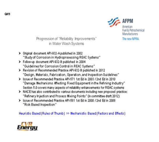
The question of issues associated with waterwash has been discussed since the API-932 was issued. This first slide gives a little chronology of some of the documents. There have been a lot of documents issued since the 932 was first published in 2002. Back then, it was called “a Study of Corrosion in Hydroprocessing Reactor Exchange Air Cooler Systems”. Part B about guidelines came out in 2004. The 932-B got republished and updated in 2012 and now refers more to design materials, fabrication, and operations of inspection guidelines. During this period of time, there has also been the issuance of the recommended practice about damaged mechanisms affecting fixed equipment in the refining industry. Section 5 thoroughly covers many aspects of reliability enhancement in REAC (reactor effluent air cooler) systems.
NACE (National Association of Corrosion Engineers)
is getting ready to come out with a very detailed report on the refinery injection: actual quills, design of the quills, designs of the manifolds, how you kick velocities, and all of the really technical details. So, in addition to API 581, all of these have been coming together in the risk-based inspection (RBI) programs.
In a nutshell, years ago, the waterwash systems and reliabilities of waterwash were based on mere heuristics, rules of thumb. Guys would say, “Well, I have so many gallons of water for so many thousands of barrels of feed.” Now it is my opinion that this has now gone to a mechanistic-based response through technology where people take a look at their effects in terms of waterwash because the damage mechanisms and prospects for catastrophic failure in hydrotreaters, in this particular area, are very high for a number of different damaged mechanisms.
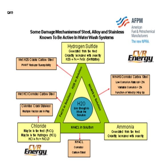
The next slide also appears in the Answer Book. I sat down and thought, well, what else is involved? I just tried to get awareness. Moving from heuristics to mechanic-based, you have to be a lot more cognizant of the chemistry that might be occurring. At the top of the triangle, you have hydrogen sulfide. It is always going to be there. In the bottom right, you have ammonia, which will always be there with the nitrogen and the feeds.
As one of the new players in the game, chlorine plays a competitive role in all of this. I do not know whether it is just due to awareness, availability, the existence of more chlorides in crudes and in intermediates, or more chloride leakage from your CCR. Chlorine is competitive with H2S for iron. There are various things going on. The iron chlorides are very corrosive.
I want to encourage people by saying that because water is in the middle of all of these, you must bring adequate water and use enough to dilute out the solution, with respect to the regular type guidelines. You also need to be cognizant of the fact that there are a lot of new issues of which people are more aware; particularly, as I said, chloride and ammonium chloride. The rough thing about ammonium chloride is that it often deposits in areas of the heat exchanger system, which is not typically accessible with your current waterwash systems. So, you often have to do an intermediate or temporary waterwash.
Some general guidelines on maximum velocity for tubes with a given salt concentration, primarily ammonium bisulfide salts: Again, you need to assure that the distribution of the water upon injection has been balanced throughout your manifolds. It is a very highly technical topic these days, so just be aware that there is a reference list published in the Answer Book. Feel free to dig up those references and read them because it is gotten very, very, very good in recent years.
PUI-NANG LIN (Flint Hill Resources, LP)
One of the questions on the waterwash system that we often have is: What kind of guideline do you use in case of a loss of the water pump? Also, how do you decide the length of time you can run without waterwash before you have to pull feed?
LEICHTY (Chevron USA, Inc.)
It depends on the concentration of ammonium bisulfide. My response to Question 25 includes a slide I have prepared to answer that question.
BODOLUS (CVR Energy)
The original API-932-A document was published in 2002, and there have been numerous publications since then that address washwater systems of reactor effluent air coolers (REAC) and associated equipment including:
1. Follow-up document API-932-B published in 2004: “Guidelines for Corrosion Control in REAC Systems”.
2. Revision of Recommended Practice API-932-B published in 2012: “Design, Materials, Fabrication, Operation, and Inspection Guidelines”.
3. Issue of Recommended Practice API-571 1st Ed in 2003/2nd Ed in 2010: “Damage Mechanisms Affecting Fixed Equipment in the Refining Industry”.
4. Section 5.0 covers many aspects of reliability enhancements for REAC systems.
5. NACE has also contributed to various documents including new proposed practice: “Refinery Injection and Process Mixing Points” (in committee draft 2012).
6. Issue of Recommended Practice API-581 1st Ed in 2000/2nd Ed in 2008: “Risk-Based Inspection”.
The newer publication is not so much a revision of the old document as they are a refinement and improvement in the knowledge base of corrosion factors and the abatement techniques that can be implemented. Older guidelines based on Heuristics (Rules of Thumb) have been replaced with a better understanding of the Mechanistic (Factors and Effects) driving the damage pathology.
From my perspective, there has been a broadening awareness of the key chemical interactions taking place in hydrotreaters reactor effluent environment. We are all aware that iron, iron sulfides, hydrogen sulfide and Ammonia play key roles in corrosive action in reactor effluent reactor air coolers, but the prevalence of chloride adds another dimension of complexity. (see Damage Mechanism Slide)

The general focus has been on the corrosive nature of ammonium bisulfide (NH4HS) in aqueous solution but additional attention is being given to ammonium chloride (NH4CL) fouling that typically occurs in process regions not services by continuous waterwash systems. As little as 1 wppm chloride in the feed will cause NH4Cl deposition in the reactors effluent circuit of hydrotreating units, depending on the feed nitrogen and the unit operating pressure.
Fortunately, NH4CL deposits areas in hotter sections of the feed/effluent exchange system (350°F to 400°F) where inherent water dew point is not an issue. As the process stream approaches temperatures consistent with reactor effluent air coolers, water dew point can occur at NH4HS deposition temperatures (80°F to 150°F). Initial depositional aqueous fluids can be very corrosive with localized rates enhanced by velocity, H2S partial pressures and/or the presence of chloride.
Introduction of sufficient, controlled quality (free of dissolved O2 and chloride) water, in the specific process location upstream of the inherent dew point, with a well-designed distribution system has shown to be the primary means to control ammonium salts. Detailed process chemical modeling of the reactor effluent stream needs to be combined with mechanical and physical aspects of the injection point design to generate an effective abatement plan. The plan needs to be monitored on a continuous basis for key process variables of water flow, resulting salt concentration in washwater loop and exchanger network DP build. Suspected corrosion regions need to be inspected online, as able, on a defined interval commensurate with known mechanical risk factors (velocity and geometry) and thoroughly inspected at turnaround opportunities. Vigilance needs to be paid to all known and potential damage mechanisms in the exchanger equipment and piping system including general and localized corrosion, SCC, HIC, SOHIC, chloride stress cracking, and hydrogen blistering.
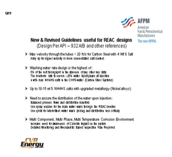
Guidelines are still useful for REAC designs using carbon steel, with a max velocity through the tubes less than 20 fps (typical API-932 recommendation) for 4 wt% salt.
Washwater rate design is the highest of:
- 5% of the unit throughput in the absence of any other key data,
- the minimum rate to ensure ~25% water liquid phase at injection,
- 4 wt% max NH4HS salts in the CHPS water (carbon steel systems), or
- up to 10 wt% to 15 wt% NH4HS salts with upgraded metallurgy (nickel alloys). You need to assure the distribution of the water upon injection by
- Balancing process flows and distribution manifold,
- Using spray nozzles for the main waterwash through the REAC bundles, and
- Using quills for intermittent waterwash (mixing and distribution less critical)
OHMES (KBC Advanced Technologies, Inc.)
Again, a lot of these comments are in the Answer Book, so I will skip through part of my remarks. People often forget about the refinery slop processing system. Typically, refiners understand where their cracked stock goes; but if it is typically or abnormally routed to the crude tanks or units, one will have cracked stock throughout the refinery, which can cause problems.
Some of the mitigation options can be summarized in four areas. The first is feed logistics. We would say that if you are going to handle this, you need to do as much direct feeding as possible. Again, it is a refinery; so, it is really not practical to be 100%. If you are going to use storage, all of the tank streams will need to be under a nitrogen blanket or a floating roof tank utilized, even if these are virgin streams that will mix with cracked stock. You will obviously need to check your tanks during regular maintenance and cleaning because, again, the primary causes and ingredients of this foulant formation are the olefins, diolefins, the iron scale around it that acts like a catalyst, and the oxygen.
Once that is under control, another option would be chemical treatment. Some people do put in oxygen scavengers; they will work. Others put in different inhibitors to stop the polymerization from forming, particularly on the initial exchangers. Again, there are mixed results in the plants. Some work; others do not. It is probably worth a trial to see if it fixes your situation.
An important area of consideration is the unit configuration. The traditional example is determining how to handle coker naphtha. Some people will have the low temperature diolefin saturation reactor upfront, which can very effective. For those who do not, sometimes putting this coker naphtha in other spots (the response given earlier about putting it in the ULSD or the gas oil unit) is an option. In Asia, many refiners actually put in oxygen strippers to help manage this issue. They will bring in fuel gas, hydrogen, nitrogen, or other media to strip out the tankage feed to remove the oxygen.
The final recommendation concerns the catalyst; and, again, I will defer to the catalyst vendors. There are a lot of different options for catalytically avoiding the polymerization from forming at the top of the reactor. Some refiners include specialized iron trap catalysts which keep that from causing those formations.
LEICHTY (Chevron USA, Inc.)
Chevron has a number of units that store cracked feeds ahead of hydroprocessing units. When doing so, care must be taken to ensure that the tanks are free of oxygen to mitigate unwanted polymerization and gum formation. With the more reactive stocks like coker naphtha, it may be necessary to inject an antioxidant into the rundown and an antifoulant in the hydrotreater feed to mitigate exchanger fouling.
UNIDENTIFIED SPEAKER (Foster Wheeler)
Regarding the storage of cracked products, what is the maximum duration that we can normally store the cracked products? Can we take the cracked products from storage directly back into the hydroprocessing or should they go back to coker or somewhere else?
OHMES (KBC Advanced Technologies, Inc.)
As long as it is under a nitrogen blanket or floating roof, you should be able to store it for quite a while. I do not really have a good rule of thumb on storage time limits, but we have seen refiners go between turnarounds storing cracked stocks. But if you do not have that capability, the cracked products will quickly form polymers. You will then need to either try to rerun the material elsewhere or just take the material, knowing that it will cause problems in the units. Most refiners just get ready for it.
OHMES (KBC Advanced Technologies, Inc.)
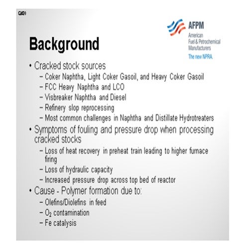
Cracked stocks can come from conventional sources, such as coker, FCC, and visbreaker. However, cracked stocks can be found in unexpected streams, such as virgin stream where cracked refinery slop has been introduced to the upstream crude and vacuum unit. The hydroprocessing units most commonly impacted by cracked stock, from a fouling and pressure drop perspective, are the naphtha and diesel hydrotreaters. Some of the typical symptoms of fouling and pressure drop (DP) problems when running cracked stock are:
• Loss of heat recovery in the preheat train, such that the reactor charge furnace has to fire harder,
• Reduced hydraulic capacity, such that flow control valves operates further open or near full-open, and
• High pressure drop across the reactor or first bed, depending on indication points.
The normal cause of fouling and DP due to cracked stock is polymer formation, which is driven by the olefins and diolefins inherently in cracked streams, oxygen contamination in the feed, and catalyzed by iron contamination. The four management options are feed logistics, chemical treatment, unit configuration, and catalysts.
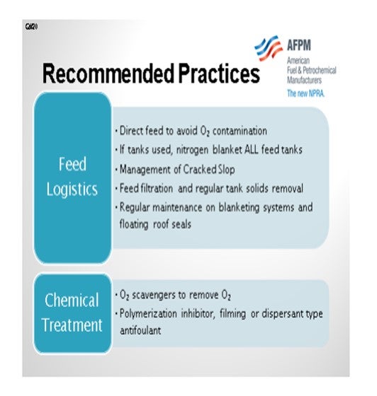
Feed Logistics
The primary cause of fouling from cracked stocks is O2 contamination. Therefore, all feeds to a hydrotreating unit processing cracked stocks should be sent from the source unit directly to the hydrotreater. If feed from tankage is sent to the hydrotreater, whether that feed is virgin or cracked, the tank should have a nitrogen blanket or should be a floating roof. Regular maintenance on the blanketing systems and floating roof seals are especially important for these services. Using the tanks in a “once-through” mode also assists in minimizing fouling.
As highlighted above, iron can serve as a catalyst to drive polymer formation. Some logistics mitigation options are to use feed filters to remove iron scale and to complete regular tank maintenance to remove corrosion products from streams coming from tankage.
Finally, ensuring that refinery cracked stocks are properly managed and processed is important. Several instances of high fouling have been traced to cracked slop being reprocessed in crude units, thereby “contaminating” virgin streams with cracked material. Normal practice is to segregate virgin and cracked slop and process cracked slop in the coker or send to fuel oil.
Chemical Treatment
Though chemical treatment is an option, the success rate is varied and depends on the severity of the fouling. For oxygen contamination, some refiners have used oxygen scavengers to contain the oxygen contamination. Other refiners have used polymerization inhibitors, filming antifoulants, and dispersant antifoulants to minimize the impact of fouling on the preheat exchangers. For reactors with pressure drop problems, chemicals are available for use to help break up the foulant and provide a temporary reprieve on the pressure drop. For these options, the best option is to discuss with your site chemical vendor to determine options and solicit positive result case studies or contacts.
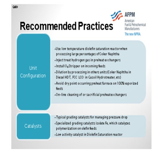
Unit Configuration
Obviously, one option is to remove the cracked materials from the unit feed, but that option is normally not practical. However, an option may exist to process some or all of selected cracked streams in other hydrotreating units. For instance, some refiners process coker naphtha in the diesel or gas oil hydrotreater, as opposed to processing in a dedicated coker naphtha hydrotreater or mixing in the virgin naphtha hydrotreater, such that the material can be diluted in a larger feed pool.
Processing coker naphtha in conventional naphtha hydrotreating units is possible and common. However, the successful units include a diolefin saturation reactor. This reactor is loaded with low activity catalyst and operated at a relatively low temperature, as the diolefins do not require normal reactor temperature not normal activity catalyst to saturate. This configuration option allows the refiner to saturate the diolefins at low severity, thereby reducing the propensity to form polymers.
From a heat recovery standpoint, several options are available to minimize fouling impacts. First, ensuring some hydrogen is available in each of the preheat exchangers helps reduce polymer formation as the liquid feed is heated to reactor conditions. Most modern designs already have this feature, but older or revamped units can have liquid-only exchangers in the hot circuit that have a tendency to foul. Some licensors and refiners have installed the capability to take exchangers out of service while the unit is in operation to allow online cleaning or have sacrificial exchangers in the preheat train. Avoid using plate heat exchangers, which are prone to fouling. Finally, as a reminder for units which will operate in 100% vapor phase, make sure that the dry point does not occur in the charge furnace, so that deposits are not placed on the furnace tubes.
A final configuration options that some refiners have used is an oxygen stripper on the fresh feed. This option involves installing a low pressure stripper tower that uses hydrogen, natural gas, or fuel gas to strip out any oxygen contamination. However, this configuration option can be capital intensive and requires regular loss of off gas to fuel gas or flare to function properly.
Catalysts
Catalysts have long been the primary reactor pressure drop control mechanism. Most refiners now employ a catalyst grading system on the top bed of the reactor to provide a mechanism to trap contaminants and manage pressure drop escalation during a cycle. Specifically for fouling due to cracked stock, several considerations are suggested:
• In addition to catalyst size grading and progression, also ensure that catalyst activity is being progressed from low to high activity. This approach is similar to the discussions above on diolefin management.
• Special grading material is available that helps better trap and isolate iron scale. Doing so will reduce the tendency for iron catalyzed polymer formation. Discussions with your catalyst vendor about catalytic options should be part of your regular catalyst selection process.
ESTEBAN (Suncor Energy, Inc.)
Hydroprocessing of cracked feedstocks is very common due to the sulfur content of coker and FCC products. These feed streams can often be sent “hot” (directly) to a downstream unit, which prevents potential polymerization reactions due to oxygen ingress at storage tanks. However, storing these materials in feed tanks can result in reactor fouling and pressure drop increase.
Blanketing of tanks that store cracked feedstocks with nitrogen or some other gas is the primary control mechanism to avoid fouling and pressure drop problems resulting from the polymerization of cracked materials when oxygen is present. In some of Suncor’s facilities, cracked feedstocks are stored along with straight run feedstocks in nitrogen-blanketed tanks. In order to ensure proper operation the control instrumentation is inspected and maintained routinely to prevent fouling issues. In our experience, we have identified a malfunctioning N2 blanketing system as a contributing cause to exchanger fouling in a diesel unit. The malfunction had allowed oxygen to enter the tank and react with the cracked material in the tank.
A secondary means of preventing fouling issues is by the use of polymerization inhibitors available from chemical vendors. These are injected into the stream entering the feed tank. Most are approved for use, by licensors and catalyst manufacturers’. However, Suncor does not have experience with these products.
ROGER METZLER (Baker Hughes)
Avoid tankage, if possible. Direct hot rundown to the HDS unit. If intermediate tankage is necessary, nitrogen or fuel gas blanketing should be employed to minimize oxygen intrusion. Treatment with Baker Hughes antioxidants and/or polymerization inhibitors can be effective when the specific polymerization mechanism is identified in order to select the appropriate inhibitor chemistry.