General Session
Session Start End
-
LEE (BP North America)
We have the chemical service vendor perform routine calculations for ammonia and/or amine salt points. We typically monitor the water dew point ourselves. The amine salt point is to be differentiated from the ammonia chloride salt point. Depending on the amine, a salt point can be higher, and often is. The amine, as opposed to the ammonia salt point, calculation is typically by special request if there are issues with the particular unit operating near the system’s salt point. It should be noted that data requirements for doing an in-tower amine salt point are more difficult and onerous than for doing an amine salt point in the cool tower overhead system for which the amine content in the sour water is readily available by direct analysis. The calculation for the in-tower amine salt point requires an estimate of the amine quantities feeding the crude tower and prior to any overhead chemical injections.
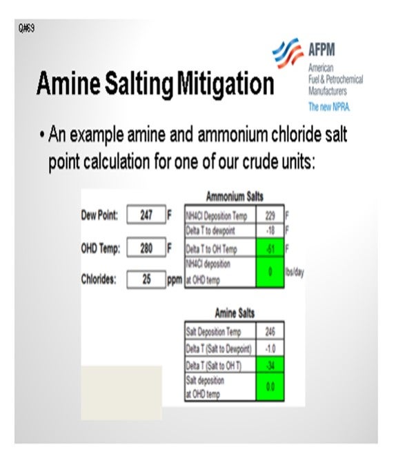
The table on the next slide shows some amine salt points for one of our crude tower overheads and compares them to the ammonium chloride salt point. In this example, the ammonium chloride is in the 229°F range, and the amine salt is 246°F in the crude tower overhead system. We try to maintain the top pumparound return temperature above the controlling salt point. We also try to operate the bulk top temperature at least 40°F above the controlling salt point. But recently, there has been a tendency with commercial drivers to reduce top temperature targets in order to maximize jet or light diesel production over naphtha production.
If the system is in a troubleshooting mode and corrosion is suspected, then samples are taken from any deposits in the top pumparound circuit and analyzed for amine, nitrogen, and chloride content. Of course, if corrosion products are present, they will be evident by significant iron and other inorganic content in the foulant samples.
Some other mitigation handles on amine salt formation include the following:
1. Optimize desalter performance to reduce hydrolyzed chloride content in the crude tower overhead. There are multitudes of desalter optimization parameters, including washwater rate, washwater quality enhancements (including pH and ammonia content), mixed valve pressure drop optimization, demulsifier use, and optimization of grid voltage settings to achieve the maximum operating temperature.
2. Use caustic injection as an operating handle if caustic injection skids and the injection quill are already available on the unit. About half of our units practice caustic injection to mitigate the chloride’s contribution to amine salt formation.
3. Review filmer or neutralizer formulation with the chemical service provider. Certain filmers and neutralizers have slightly lower amine salt point than others, and there are tradeoffs in performance.
4. Operate the top temperature of the crude tower or elevated temperature, which will increase the operating margins of the salt point. This is in commercial conflict with the typical current financial drivers to minimize overhead naphtha production while increasing jet or kerosene. There will be short-term yield optimization versus long-term availability tradeoffs.
5. If possible, increase the top pumparound return temperature. Again, the idea here is to increase operating margins to the system salt point while trying to maintain the required crude tower heat removal.
6. Perform continuous washwater injection at the location of salt deposition.
DION (GE Water & Process Technologies)
As previously discussed, the ionic equilibrium model is an extremely important tool to define the safe operating envelope for your unit. Most specialty chemical suppliers have an ionic equilibrium model. GE’s ionic equilibrium model is called LoSalt*. I cannot stress enough the importance of running these models as frequently as possible. Various scenarios can be examined in advance to predict when particular parameters would increase the risk for salt corrosion. Different neutralizing amines will have different salt points. Selecting a low salting amine will minimize salt corrosion potential. Then explore the other parameters, such as the upper limit for tramp amines, chlorides, and stripping steam. The best-in-class corrosion control program will look at all of these factors: metallurgy, mapping and eliminating tramp amines, overhead waterwash, an effective filmer, and the appropriate neutralizing amine.
DEAN WONG (Husky Energy)
We have heard a lot of good information about desalting operations, but does the panel have experience removing crystalline salts as the feed gets heavier, the easy salts?
DION (GE Water & Process Technologies)
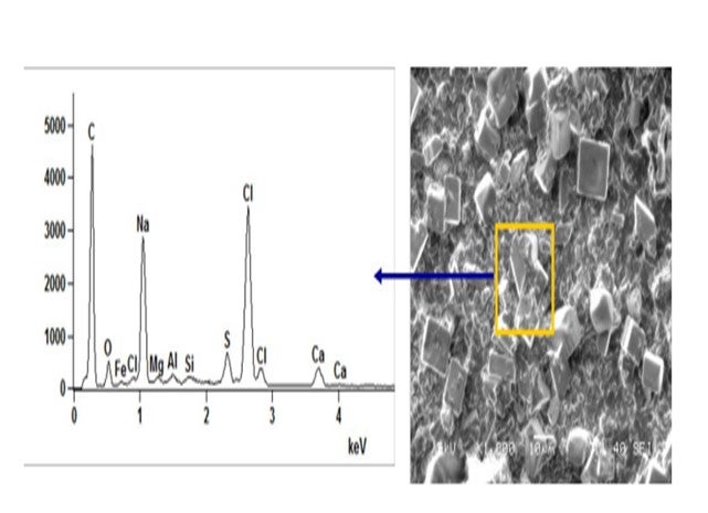
Crystalline salts exist in crude. Below is a microscopic picture and analysis of raw crude after filtration. The topic of “encapsulated” or “asphaltene-coated” salts has been mentioned in the past. In general, their removal can be improved by working the desalter harder. The crystalline salts must contact the washwater to be removed from crude. The desalter is designed to make an emulsion, wash impurities from the crude, and then resolve the emulsion. A finer emulsion, using mix valve and washwater rates, can be utilized to improve salt removal efficiency. The Salt by Extraction Test should measure all extractable chlorides. The procedure includes adding hot toluene to the crude in a separatory funnel. In theory, the toluene should remove the heavy oil and asphaltene coating from the crystalline salts.
RUSSELL STRONG (Champion Technologies)
I love this topic, but I will not take too much time. Let’s go back. The question says, “How do you detect if amine salts are forming and causing corrosion?” I will read that as “…have formed and are causing corrosion”. A main consideration has to do with neutralizer injection. In the case of a neutralizer, if it goes in as a liquid, which is typical, then it will take time for it to absorb the latent heat. The neutralizer will need to evaporate in order to work according to modeling. In the course of that evaporation, it will have ample opportunity, while as a liquid, to react with HCl vapor. That problem is seen in a lot of refineries, particularly if they do not have the right kind of injection system to inject the neutralizer as a vapor.
In some cases, even if you think you have a good injection system, you may still have a similar problem. A high concentration of salt can form, caused by amine recycling to a higher and higher concentration. Modeling may not have adequately considered the amount of neutralizer partitioning into reflux and/or into the desalter crude, which then cycles back to the overhead.
All that being said, let’s get to the question of detection. You can usually tell if salts have formed ahead of the water dew point. Pull out a corrosion probe/coupon from upstream of the calculated water dew point and examine it using EDS-SEM (energy dispersive spectroscopy-scanning electron microscopy) analysis. You can see any chloride that may be on that probe/coupon. The chloride will have been deposited in a salt form. HCl vapor is certainly not going to condense ahead of the water dew point.
The trouble with knowing whether or not it is an amine chloride, ammonium chloride, or some other form of chloride is that when corrosion occurs, the salt forms metal-chloride. The amine/ammonia has nothing to hold it in place. It tends to evaporate away from the deposit, and subsequent examination will show significantly less amine than was originally present. Alternatively, if you cannot do the above analyses, a chloride salt on your corrosion probe, on which you had an amine salt or an ammonium chloride salt, tends to top out around 50 mils a year unless there is a velocity-assisted component that accelerates the corrosion. If it is less than that, the problem is not as serious as it could be.
DION (GE Water & Process Technologies)
A more complete understanding of the overhead system dynamics is the first step in properly diagnosing the corrosion and fouling potential of a given unit. In the past, this has been accomplished retroactively following the failure of system equipment. However, a proactive approach to amine salt precipitation prediction and corrosion mitigation is a much more efficient way of controlling overhead corrosion. A highly effective means of determining the formation of amine salts is through the use of ionic modeling software. The use of a robust and rapid ionic modeling tool will allow for the calculation of the salt precipitation temperature, or “salt point”, of the neutralization salts and water dew point (ICP) temperature. The use of such a model allows for rapid evaluation of current system variables and operating parameters. With this information, asset operators can potentially adjust tower operating conditions (e.g., overhead outlet temperatures) to manipulate the location in the overhead system where the neutralization salts precipitate. Use of the model also allows for the development of an “operating envelope” for the tower and overhead system that keep the amine salts from forming in unwanted areas of the overhead circuit across various desalter effluent chloride ranges. GE has successfully implemented this control and mitigation approach at a client site using its LoSALT* Ionic Modeling Tool and the refiner first consults with the local representative to evaluate potential tower operational changes prior to adjusting process conditions.
Beyond operational adjustments, a “three-prong” approach of neutralizer, waterwash, and filming corrosion inhibitor should be employed to mitigate corrosion by amine salts. First, an appropriate neutralizer must be selected to minimize the neutralization salt precipitation temperature while effectively controlling ICP and accumulator pH within acceptable ranges. Lower salt-point amines should be utilized in the overhead treatment program to minimize salt formation in the overhead system ahead of the water dew point or in the fractionator tower itself. Secondly, an effective waterwash protocol must be implemented to raise the amount of free water in the system and provide a means of washing away any precipitated amine salt deposits. The last portion of this chemical treatment approach is to introduce a quality filming corrosion inhibitor to protect the metal surfaces against corrosive attack. Some quality filmers will provide a level of salt dispersions to further aid in the movement of amine salts through the system and reduce underdeposit corrosion related to these salts.
Tramp amines that enter the distillation column with the desalted crude contribute to higher salt point temperatures in the overhead. An often-overlooked operational strategy is source-reduction of the tramp amines that would drive the overhead salt point to higher temperatures. Developing an amine-map of the refinery’s amine sources can aid in rapidly identifying and eliminating tramp amines entering the overhead system. Additionally, chemical treatments can be implemented at the desalter to increase amine extraction into the desalter effluent brine and prevent them from reaching the tower overhead.
BASHAM (Marathon Petroleum Corporation)
Ionic modeling is the only way to predict. High pressure drops across the top couple of trays could point to a buildup of fouling material from corrosion. The top temperature of the crude tower should stay above 300°F to ensure that no corrosion happens in the tower. Consideration should be given to ensuring that the top pumparound return temperature is well above the water dew point temperature to avoid shock condensation of water vapor. Also, reflux should be introduced onto the top tray with a spray header to allow it to heat up and not cause shock condensation.
RANDY RECHTIEN (Baker Hughes)
The best method for determining the formation potential of amine-HCl salts is the use of Baker Hughes Ionic Model technique. This method provides for the rigorous calculation of salt formation temperatures under all operating scenarios. Once the root cause of the salt formation has been determined, multiple mitigation options can be examined using the Ionic Model. These mitigation options include the following:
• Improved desalting operation to reduce overhead HCl levels,
• Caustic injection to desalted crude to reduce overhead HCl levels,
• Application of alternative neutralizers with lower salt-forming tendency,
• Installation of continuous waterwash to the overhead, and
• Increased tower operating temperatures.
DENNIS HAYNES (Nalco Energy Services)
Salt formation in towers would result in restricted flow and reduced distillation performance. Where salt formation is towers is suspect, as tower scan would assist in determining location and severity. Overhead lines that are suspect for salt formation should have UT reading periodically done and changes in corrosion rates would be an indication. Both of these points are after-the-fact measurements; so more importantly, utilization of modeling to determine salt points in process towers would lead to an early indication of potential problems.
When salt has formed and needs to be dealt with salt dispersant chemistries have an effective history in the industry. Operationally, slumping the tower and applying a waterwash is possible; however, much planning and care is required due the introduction of water into a potentially hot system. If salt formation is possible, washwater, additional steam, adjusting tower temperature, and pressure are all variables that may be used to change dew point and salt points.
BASHAM (Marathon Petroleum Corporation)
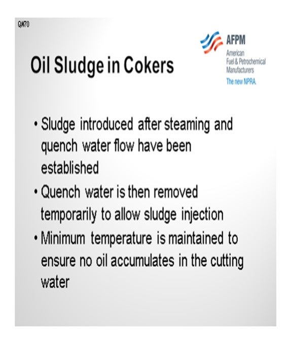
One of our delayed cokers does process crude rag layer draw, wastewater sludge, and oily water. I think they primarily process the crude rag layer, however. What we do here is introduce the sludge after we have steamed the coke bed and established the quench water flow. We then temporarily remove the quench water to allow the sludge injection, and then we maintain a minimum temperature – I think it is around 600°F – to ensure that no oil accumulates in the cutting water. We also have to take a look at the cutting water to check for any emulsion. If it is milky-looking and has a foul odor, then we know we probably have either too much injection or our temperature is too low.
TRAN (Houston Refining LP)
We do a similar process at one of our delayed cokers at the Houston Refinery. I want to add that we have experienced hot drums issues due to sludge processing the slurry. When we did the particle size distribution, we found that the volume of solids in the water injection was higher than typical, as was the size itself. We mitigated it by reducing the injection rate and the number of solids in the slurry mixture, and then requested that the site itself grind it down a little smaller.
MIKE FINK (CITGO Petroleum Corporation)
What sort of limits do you put on percent oil and percent solids?
TRAN (Houston Refining LP)
We try to keep the solids to under 1%. In terms of micron size, the majority of it is typically below 25µ (micron). The whole range is up to about 100µ.
AHMAD AL-JEMAZ (Kuwait National Petroleum Company)
Can you still maintain anode-grade qualities affecting the sludge in the coker?
BASHAM (Marathon Petroleum Corporation)
Yes, we can.
TRAN (Houston Refining LP)
We do not have any experience producing anode-grade coke.
AHMAD AL-JEMAZ (Kuwait National Petroleum Corporation)
What are the specific parameters that you monitor in the sludge to avoid affecting the coke quality?
BASHAM (Marathon Petroleum Corporation)
As Don mentioned, some of the parameters are particle size and amount of sludge being injected. You also have to watch the minimum temperature, as I mentioned. That is all the experience that we have on it. We do not do a lot of injection, but I am not aware that we have had any coke quality issues. The primary concern is the effect on the cutting water.
BASHAM (Marathon Petroleum Corporation)
One of our delayed cokers processes a crude rag layer draw, wastewater sludge, and oily water. These components are processed after steaming and establishing flow with the quench water. Quench water is removed temporarily to allow injection of the sludge. After the sludge injection is complete, quench water is reintroduced. To minimize the potential for accumulating oil in the cutting water, the amount processed and the minimum temperature of the coke drum minimum temperature are both regulated.
TRAN (Houston Refining, LP)
We process slurry between the steam stripping and water quench steps. We limit the slurry injection amount based on the coke drum outlet temperature. The slurry stream contains solids which can cause reliability issues on pipes and pumps. We have also seen coke bed plugging issues that have resulted in hot drums and fallout. Some of coke morphology issues have been alleviated by reducing the slurry injection rate, the solid amount in the slurry, and the solid sizes.
LEE (BP Products North America)
We have some experience with quench injection as a method of recycling sludge in the coker. This involves injecting it with quench water at the beginning of the coke cooling step. To minimize problems and maximize sludge processing a refiner should: Prepare the sludge to have little or no free oil and small particle sizes (usually performed by an experienced contractor; centrifuge to recover free oil and grind to obtain small particle sizes), and strictly limit the amount of sludge injected (usually limited by a combination of time, quantity and/or drum temperature). It is important that the sludge injection is discontinued at a drum outlet temperature of not less than 550ºF to insure the oil is recycled through the blowdown system. If not done correctly, sludge processing on the coker can contribute to severe odor problems when the drum is opened and with the coke in storages, problems with drum cooling if the sludge particles are too large (can contribute to water channeling and subsequent hot spots/eruptions), problems with draining the coke drum prior to decoking, and increased coke toxicity and industrial hygiene issues.
Active drum sludge coking is another option where this sludge is slurried with oil and injected into the coke drum during the coking phase. BP has one site that does active drum sludge injection through the top of the drum. Sludge injection during the coking phase takes up some coker capacity. Typically, there are not the same problems with odorous coke. Injection rates need to be as low as possible to prevent lowering the drum overhead temperature and increasing coke make and preventing the coking reaction temperatures from being too low. Sludge injection should be discontinued approximately three hours prior to the drum switch to get the drum outlet temperatures up to convert any unreacted material.