Question 28: Our hydrotreating unit continues to suffer from pressure drop issues. Multiple graded-bed schemes have provided incremental improvements. What other successful solutions to further mitigate pressure drop buildup do you employ?
PETER BENDTSEN (Haldor Topsoe, Inc.)
Solving reactor pressure drop issues has been a decades-long ongoing effort, and Haldor Topsoe has been a pioneer within this area since the early 80s when Haldor Topsoe first commercialized highly effective catalytically active grading products.
Grading and Chemical Injection
Expanding the grading system will directionally improve onstream time before a unit reaches its pressure drop limitation; and by simply increasing the volume allotted for grading, you will proportionally increase the storage volume for particulates introduced with the feed and/or for storing polymerization products formed from the reactions of very reactive feed species, such as olefins and, in particular, diolefins. However, this process may not always extend the cycle length proportionally for a number of reasons. The key lies in thoroughly studying the pressure drop formation mechanism and engineering a solution that addresses the underlying cause(s).
An example where expanding the volume of the grading system may fall short of expectations is with NHT (naphtha hydrotreater) units that experience drypoint in the furnace or with NHT units that process coker and FCC naphthas. In these situations, flakes of coke spall from the furnace tubes and are carried to the top of the catalyst bed with the process stream, where these flakes/chunks plug the very top part of the catalyst bed, independent to how much grading or hold-down materials installed. One obvious remedy is good monitoring of the drypoint and operating the unit such that drypoint happens in the upstream heat exchangers. This monitoring often means overtreating, with respect to the product specifications on sulfur and nitrogen, for example, at SOR, but it does allow for an overall longer cycle length of the unit.
Another example are units that process feeds containing oxygen and/or diolefins where polymerization occurs in the preheat train, which may also lead to pressure drop problems, as these reaction products enter the reactor overtime. Here the remedies include good nitrogen blanketing of tanks, the use of oxygen scavengers (chemical injection), and diolefin saturation reactors.
Depending on the nature of the pressure drop problem, other chemical injections may be helpful in a given scenario. There are dispersants available for carbonaceous-driven pressure drop problems; and if a pressure drop problem has already manifested as a result of corrosion (Fe)-based products, then injecting a coagulant may help reduce the pressure drop problem and allow a unit to operate until its EOR date. There are a number of precautions that need to be taken when using chemical injectants, and the chemical supplier can offer advice on this.
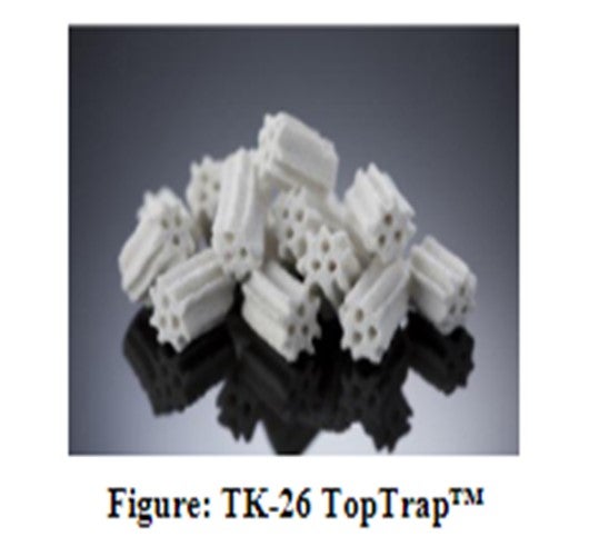
TK-26 TopTrap™
To handle particulates introduced with the feed, in particular inorganic iron, HaldorTopsoe launched the microporous particulate trap called TK-26TopTrap™, which is an industry-leading trap material.TK-26TopTrap™ is manufactured in an optimized multi-lobe shape with three axial holes to provide about 20% higher pickup capacity as compared to its industry-provenpredecessor,TK-25TopTrap™.TK-26TopTrap™is designed to give a 61% particle void fraction, in addition to a large internal pore volume, as a result of its macropore system.
Larger sized inorganic contaminants deposit in the spaces between the particles; fine or smaller sized materials enter the pore system and are trapped within the structure of the particle itself (see figure below). The internal void of TK-26TopTrap™is 25%, so that the total void in this product is greater than 85%.
Operational Changes to Extend Cycle Length
In the situation described above where a pressure drop problem has already developed, there are some operational moves that can be made to ease the pressure drop problem and help extend cycle length to the planned EOR date. One effective option is to gradually reduce the recycle gas rate and run closer to unit dP limit (dictated by outlet collector, bed support). While reducing the recycle gas compressor rate may be effective in lowering the reactor pressure drop, it will increase the coke fouling /deactivation rate of the catalyst system. If the catalyst is determined to be removed at shutdown and has sufficient catalyst activity, this process revision is one viable option which can be applied in commercial operation. Another option is to perform an LCO flush and/or a hot hydrogen strip. Haldor Topsoe can supply recommended procedures for these two scenarios.
Technology Solutions
Feed Filtering
One option is to reduce the filter sizes / openings in existing feed filters and accept more frequent replacements, cleanings, and backwashes. If a unit is not already fitted with a feed filter, this may, in many cases, prove costly or difficult due to plot space, etc. In addition, there are new procedures to be adopted with feed filter cleaning/exchanges.
Scale Catcher
Haldor Topsoe offers highly effective scale catcher technology for both vapor-only (naphtha hydrotreaters) and mixed-phase (trickle-bed hydrotreaters). A scale catcher is an engineered mechanical device that is installed in the top of the reactor in the head space above the top tangent line and above the distribution tray. This technology can be easily adopted into existing unit configuration schemes, and the cost is typically very low compared to the return including significant extensions in cycle length, often more than doubling cycle lengths for units limited on pressure drop.
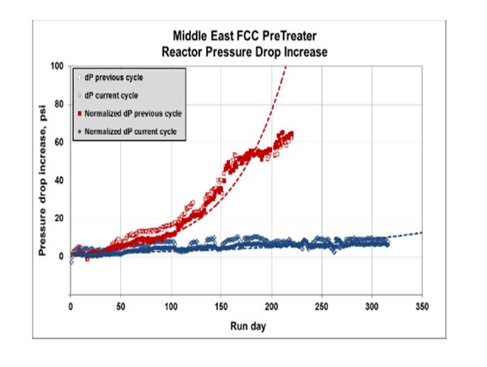
The plot below shows the successful installation of a Haldor Topsoe mixed-phase scale catcher in an FCCPT in the Middle East, where pressure drop issues have been eliminated after the installation of the scale catcher.
For more information on Haldor Topsoe Scale Catcher Technology, please refer to Haldor Topsoe’s answer to Question 8.
CHRIS CLAESEN (Nalco Champion)
First, the root cause needs to be determined. If the dP is caused by corrosion products due to corrosion in the upstream refinery units, the corrosion in these units can be reduced by applying the proper corrosion control program. If the dP is caused by gum formation, the gum formation needs to be controlled by applying a program in the feed and storage system. For resid hydrotreaters, dP often is caused by solids and metals in the desalted crude; some of these can be reduced by applying a removal program in the desalter stage. While we recommend that the focus should be on prevention measures, we have successfully reduced hydrotreater dP on many units by applying an online cleaning program.
PATRICK GRIPKA (Criterion Catalysts & Technologies)
Pressure drop issues can be difficult to solve, but the number of units with severe and chronic delta pressure (dP) issues have been significantly reduced over the last 15 to 20 years due to the time and effort spent in understanding the root causes of a particular unit’s dP issues by testing and sampling of the spent catalysts, followed by:
*Improved feed filtration,
*Feedstock management,
*Use of catalyst grading systems that provide size and activity grading, and/or
*Use of specialized hardware like scale catching trays and filter trays.
No matter what your underlying cause of dP –for example, feed filtration, equipment fouling resulting in Rx fouling, corrosion products fouling, salt deposition, etc., filter trays will always help the issue. In the simplest sense, filter trays increase the surface area available for contaminant deposition without reducing overall catalyst volume.
Our sister company, Shell Global Solutions, has filter and scale catching tray elements installed in over 100 vessels. The first filter tray design was installed in 1991; the first scale catching tray, in 1997. Shell is currently on the fourth generation of improvements on these technologies as we continually innovate and learn from the performance of this hardware in vessels in our Shell and Joint Venture refineries, which we own and operate, and in customer refineries that we service.
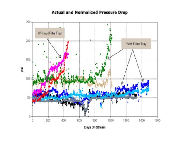
I want to share a couple examples of situation with which I have personally been involved and which convinced me of the value filter trays can provide. The first example is an FCCPT unit processing vacuum gas oils, coker naphtha, and heavy coker gas oil. This unit historically had 12-to14-month cycles, as you can see from the graph below, on cycles marked “without filter tray”. The first cycle after the filter tray (green and brown data) was significantly longer but was shut down on dP due to compressor salting issues. The two subsequent cycles (light and dark blue, black and gray data) were about four years long. These cycles ended on activity,not dP. A great success story! A filter tray has completely alleviated the short cycle shutdowns due to dP.
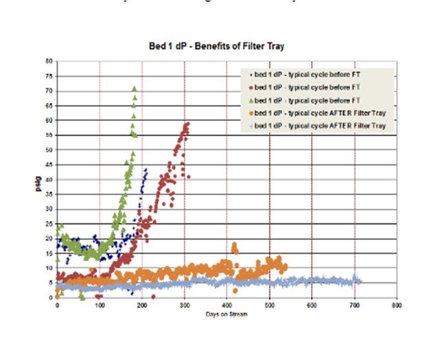
In another example, a unit had multiple very short cycles (six to 10 months; shown in green, blue, and red in the graphs below) due to significant corrosion products that caused dP issues in Bed 1. Grading schemes were improved from cycle to cycle using all possible sizes and types of grading with very little improvement in cycle length observed. The amount of foulant was just too large to be handled by grading alone. The cycles after filter tray install (orange and light blue) were much longer (18 months and 22 months). And the cycles after the filter tray was installed were shut down due to activity and not dP. A great success story!
A Shell filter tray provides chemical and physical fouling abatement, and each of the filter elements on the filter tray is in the top head of the reactor so active catalyst volume amounts are notreduced. The filter elements are typically filled with the smallest size of catalyst in the reactor (e.g., 1.3 mm preferred). The figure below gives a picture of an assembly. The technology is continually being improved. One of the latest developments is to fill one of the filter elements on the filter tray with grading layers and leave the top open so the feed can run directly through. This technique allows for a quick grading evaluation upon opening the reactor.
A scale catching tray is used for physical fouling abatement and scale trapping. Typically, these are used in reactors which are operating in vapor phase or where the particulates are very large (i.e., scale). These trays also sit above the distribution tray in the top head of the reactor.
Repeated cycles with dP issues should not be allowed to continue. There are good, proven solutions to use if feedstock management and grading improvements are not sufficient to resolve the issue.
DENNIS HAYES (Nalco Champion)
Depending on the type of foulant that is causing the pressure drop, a selection of antioxidant or dispersant or combination may reduce the quantity of material that is promoting the pressure drop increase. If oxygen from tankage is promoting reactions that increase the quantity of the foulant material, then we recommend an evaluation of how feedstock storage tankage is sealed or how blanketing with an inert gas has been utilized to minimize pressure drop build over time.
RON PARISE (Nalco Champion)
Fouling in a hydrotreater reactor bed is typically in the top section of the bed, the result of inorganic buildup (FeS) or organic deposition (polymers). Depending on the type of foulant present, there are several approaches that can be applied. There are treatment chemistries available that can agglomerate FeS molecules present in the reactor bed into larger molecules. This process permits flow to be restored to the reactor bed, relieving the delta pressure. There are also dispersants available that can disperse scatter the polymers that may be present to relieve the pressure drop in the bed. It should be noted that these are not permanent solutions; but rather, they provide temporary relief that can permit continued operation until such time as the refiner can schedule an outage to either skim the reactor bed, replace the catalyst, or implement alternative mechanical solutions.
GOPI SIVASUBRAMANIAN (Arivegry LLC)
A pressure survey could indicate other areas of pressure drop in the HP (horsepower) loop. Disproportionate pressure drops in certain components, due to hydraulic limitations or fouling, could be easily identified. However, if it is just the reactor(s) that are of concern, if catalyst loading and feed impurities/filtration issues are accounted for, a CFD study could identify if any internal is contributing disproportionately to pressure drop.
RALPH WAGNER (Dorf Ketal Chemicals LLC)
Increased hydrotreater pressure drop can significantly reduce refinery production. Fouling is a common cause of increased pressure drop, and one needs to understand the precursor of the fouling. Eliminating or minimizing fouling may increase the run-length by several weeks or months.
Iron sulfide is a common inorganic precursor which may originate in the crude as salt or organic form. FeS may also originate as a product of corrosion. It deposits on the catalyst’s surface and causes increased pressure drop. A FeS dispersant or anti-agglomerate can provide temporary relief by reducing deposits on the catalyst’s surface. A more permanent solution is to more effectively control corrosion if it is the source of FeS. If the crude is the primary source of FeS, then the options are to change crude or increase desalter performance. Dorf Ketal’s reactive adjunct desalter chemistry can be added to the emulsion breaker to increase desalting efficiency and remove metals such as iron.
Fouling and/or catalyst impairment in gas oil/residual hydrotreaters is a recent development and has been attributed to high calcium and phosphorus content. Calcium coming from opportunity crudes can be removed in desalting by using calcium removal aid such as Dorf Ketal’s reactive adjunction desalting chemistry or proprietary organic acid. If phosphorous fouling is occurring and the refinery is processing high TAN crude, the use of conventional phosphorus-based corrosion inhibitors can contribute significant quantities of unreacted phosphorus to the hydrotreater. High phosphorous loading can be avoided by using low phosphorus TANSCIENT™ high temperature corrosion inhibitor.
Polymer formation and coking on catalyst is very common during cracked feedstock processing. Mitigations include reducing hydrogen gas flowrates, reducing unit operating pressure, and performing hot hydrogen stripping, which has operational risk. Chemical treatments include use of antioxidant or dispersant antifoulant. Dorf Ketal offers these types of treatments.
Year
2016
Process
Question 29: What level measurement technology is used in the hydrotreater high-pressureseparator? Is the recommendation different if the unit runs in block modes (with feeds of varying densities)? What design considerations should be taken into account when selecting a high-pressure separator level control valve?
DAVID SACKS (Shell Global Solutions)
Level Measurement
Like any instrumentation, there are advantages and disadvantages for different types of instrumentation in almost any service; therefore, there is no single choice of a Best Practice in all situations. Experiences vary from refiner to refiner, and even sometimes from unit to unit within a refinery depending on many factors, both technical and non-technical. It is important to understand the choices within both contexts. As the non-technical factors –such as instrument technician experience, refinery standards, etc. –are too general, they will not be addressed directly.
From a technical perspective, there are multiple types of level instruments that can be used in a high-pressure separator.
1.Displacer level instruments are an old technology and are rarely specified today for straight level measurement. They are subject to maintenance issues, depending on the material and operating changes, and can have mechanical issues with the displacer.
Displacers are calibrated/configured for a specific liquid density; and as such, if the density changes, they will not indicate the level accurately, except at 0 percent: the further away from the liquid design density, the greater the error of indication. Additionally, in high-pressure services, the vapor density may become a factor and the service can behave more like an ‘interface level’ instrument as opposed to a straight ‘level’ instrument. In this case, the vapor density should be considered as part of the level calculation and displacer configuration/calibration.
Displacers are still utilized in interface level service (water accumulator between the water phase and the hydrocarbon phase). Depending on how dirty the water phase/hydrocarbon phase is, however, the mechanical issues with the displacer element ‘sticking’ can become problematic. If the level range is small and the service relatively clean, a displacer can be a good choice in this area. A calibration procedure at service pressure should be developed and executed, as interface level displacers are particularly subject to calibration shifts, away from common wet calibrations performed at atmospheric pressure.
2.Differential pressure transmitters are also an older technology, but they are relatively inexpensive and can be effective as long as they are configured and maintained properly. Characterized “Smart” dP transmitters are very easy to set up and maintain and easy to reconfigure for the case of changing liquid densities. Like displacer instruments, they are configured for a specific liquid density; and as such, if the density changes, they will not indicate the level accurately: the further away from the liquid design density, the greater the error of indication. Also, like displacers, in high-pressure services, the vapor density may become a factor and the vapor density should be considered as part of the level calculation and dP configuration/calibration.
The most significant issue for dP transmitters being set up for level measurement in a pressurized vessel is the “reference leg” connection to the vessel above the liquid level. This “wet” leg needs to be filled with a fluid of a known density. Common fill liquids are 100% glycol and 50/50 glycol/water mixture. Over time, due to various reasons (leaks, process upsets, unit depressures, maintenance mistakes), this fill fluid can become missing and/or displaced with process and the resulting density change results in a measurement error.
For a fouling service or service with very heavy liquid with a high viscosity, capillary seals would generally be recommended for dPlevel transmitters. Capillary seals also address the filled “wet” leg issues listed above, since the seal liquid is not subject to liquid displacement, unless the seals are damaged. Capillary seals are very effective when installed properly but are expensive and fragile and if damaged, require factory repair. They are also subject to thermal expansion from variations in ambient temperature (i.e., one leg in the sun and the other leg in the shade), but this variation is typically less significant than the issues that come with “wet”legs. Installation of capillary seals should include “calibration rings” between the capillary flange and the piping isolation valve. These are necessary to enable checking functionality of the transmitter without the very difficult effort of disconnecting and removal of the capillary pancake/flange.
Both wet leg dPtransmitters and connections to capillary seals need to be heat-traced, especially if there is the potential for hydrates in the service. If hydrates are a potential, the heat-tracing must bevery thorough and cover all points of the process connections. Even seemingly insignificant gaps in tracing and insulation on piping and/or impulse line tubing have resulted in process connection freezes, totally erroneous level measurement signals, and resulting process upsets.
In an interface level service, a differential pressure instrument can be effective, but the differential range required may be very small depending on the density difference between the water phase and the hydrocarbon phase. If the process density difference is small, reference leg density errors (either wet leg or capillary seals) can be very significant, relative to the configured range of the transmitter. For this reason, using dPtransmitters for interface measurement needs special attention paid to the reference leg design in order to stabilize the reference leg density.
3.Magnetic level gauges have been almost entirely replacing glass level gauges over the past 20 years. Once the decision has been made to install a magnetic level gauge, the incremental cost of an integral transmitter is essentially insignificant, compared to the total installed cost of the magnetic level gauge itself. Due to the small additional cost of the transmitter, magnetic level transmitters can make a good secondary “diverse” measurement transmitter. Magnetic level transmitters use actual floats, so they are less susceptible to changing liquid densities than displacers or dPtransmitters, as long as the liquid density is adequate to keep the float from sinking. Magnetic level gauges (hence, the transmitters) are subject to sticking in fouling service. The technology used to monitor and transmit the float position is not as straightforward as a simple displacer or dPtransmitter.
4.Guided wave radar instruments are gaining popularity. They can require more initial setup attention than a differential pressure transmitter and can be more difficult to troubleshoot, thereby requiring special equipment/software. Often a manufacturer’s representative is needed to optimize the application. The benefit is that when guided-wave transmitters have been set up properly and there is an adequate difference in the dielectric constant between the liquid and vapor phases, they have proven very effective. For some existing troublesome level measurement applications, guided-wave transmitters have been applied. Good success has been observed when there has been dedicated case-by-case application engineering. An additional benefit to guided-wave radar is that their measurement is not subject to changes in liquid or vapor density as they measure the exact liquid-vapor interface (the change in dielectric constant). Fouling can be a problem for these instruments if the liquid has the potential to leave a ‘coating’ on the instrument probe. There is some concern regarding reliability of these instruments.
Guided wave radar instruments are being used for interface level applications as the dielectric constant between hydrocarbon and water is typically quite high. The interface needs to be well defined as it is difficult to anticipate how an emulsion or “rag layer” will be interpreted by the instrument. As with straight level measurement, case-by-case setup is often the key to success for interface measurement with guided-waveradar instruments.
Because guided-wave radar is less common at many locations, the non-technical factors –such as instrument technician training, operations comfort, and general aversion to new technologies –must be considered.
While there are other technologies available that are more exotic and more expensive, the four listed above are the most reasonable choices for cost, reliability, and commonality.
For the letdown control valve from either the hydrocarbon liquid and/or water boot, several factors need to be considered:
1.This service typically has a very high-pressure drop such that a multiple-stage or angle-type control valve body would be most appropriate.
2.If there is potential for fouling, particulates, or chunks of solids in the material, the valve vendor must be made aware of this potential. If the pressure drop is driving a multiple stage-type valve selection, it will require specialized trim that has holes/channels large enough to pass the solids.
3.There is typically significant off-gassing across the hydrocarbon control valve that must be considered in the sizing calculation and the valve design.
4.The actuator sizing must be robust enough to handle the required shutoff pressure, and flow-to-open versus flow-to-close configuration must be considered in the actuator sizing.
5.The usual considerations for corrosion must also be considered as these services, especially the sour water service, which may be prone to NH4HS (ammonium hydrosulfide) or chloride corrosion depending on the expected composition of the water.
Year
2016
Process
Future Leader Welcome Reception
Session Start End
-
Question 30: What technologies do you use for mild hydrocracking of heavy gas oil over a range of conversions and product selectivity? Please elaborate on commercial experiences.
PATRICK GRIPKA (Criterion Catalysts & Technologies)
The theory and key considerations in utilizing mild hydrocracking (MHC) in an FCCPT unit were covered very thoroughly in Question 77 in the 2009 Answer Book, so I will not repeat what I consider to be the basic background information. Instead, I will try to compare the actual results achieved commercially from the various options. Several different technologies are available, and I will only highlight the keys.
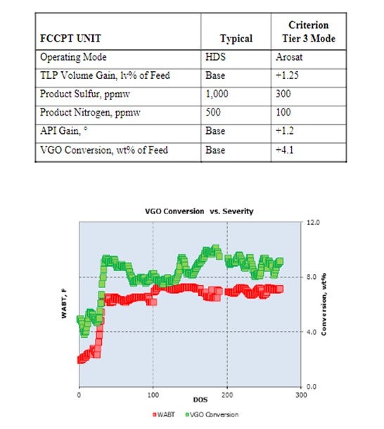
A traditional FCCPT unit with heavy gas oils operating in HDS (hydrodesulfurization) mode to meet a sulfur level specification of 1,000 to 2,000 ppm sulfur in the hydrotreated gas oil being sent to the FCC typically has 650°F+ conversion levels of 5 to 10 wt%. This conversion level can typically be increased another 3 to 5 wt% by operating at higher WABTs to improve aromatic saturation. In addition, the FCC feed quality will be improved, and FCC conversion will increase.
An excellent example of this level of improvement is a unit going from typical 1,000 ppm product sulfur to an aromatic saturation operating mode with a 300-ppm product sulfur. This improvement allows Tier 3 specifications to be achieved as shown in the table below, as well as an increase in VGO (vacuum gas oil) conversion to distillate of 4.1 wt%, as seen in the graph below. This success was achieved with our latest generation CENTERA™ catalysts. Cycle life has still been excellent at greater than 36 months. The performance benefits are illustrated below in the following table and plot. A FCCPT unit can be operated at even higher temperatures to further increase conversion, but this operation is usually not attractive due to reduction in cycle life.
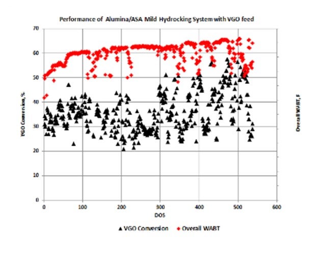
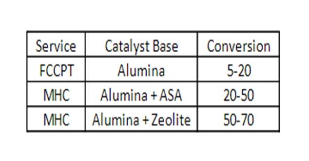
When higher levels of conversion are desired, addition of a catalyst to provide mild hydrocracking is needed. Our customers are operating many units with MHC catalysts in this mode. When higher distillate selectivity is desired, an alumina/ASA catalyst system can be considered. If even higher conversions are required and some additional naphtha and light ends can be accommodated, then alumina/zeolite stacks can be used.
Units operating in MHC mode with an alumina/ASA stack of CENTERA™ NiMo / Zeolyst ASA catalysts will have 650°F+ conversion levels of 20 to 50%. An example of the VGO conversion levels of one of our customer’s operating units (along with the excellent catalyst stability) is shown in the figure below. Middle distillate selectivity is consistently in the 80 to 90% range with this catalyst system.
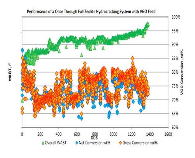
The following is an example of a higher conversion unit operating with alumina/zeolite cracking system operating in the 70 to 80% conversion range.Conversion levels beyond 50% are well within the capacity of an appropriately designed unit and catalyst system operating in once-through fashion. Applying an advanced hydrocracking pretreat and full zeolite cracking system can extend unit operations to the 70 to 80% conversion range with stable yields and exceptional selectivity. While this conversion level is on the border of what might be considered MHC operation, there are several benefits to once-through operations, even in units designed for higher conversion. Once-through operations provide consistent high conversion levels at elevated unit rates, as well as a significantly upgraded unconverted oil product stream ideal for FCC operations. The following plot illustrates a unit operating for 48 months consistently providing VGO conversion levels in the 70 to80% range.
In summary, technologies are available for hydrotreating VGO to a range of conversions. The simplest is a standard FCCPT unit operating primarily to provide high quality hydrotreated feed to an FCC. Operating the FCCPT unit for improved aromatics saturation will result in even better FCC field quality and will reduce the impact on downstream FCC gasoline hydrotreaters or eliminate the need altogether.
The mild hydrocracking operation with an alumina/ASA catalyst or an alumina/zeolite-based catalyst system will produce a high-quality bottoms product and a good to excellent quality ULSD product. Depending on unit capabilities and feed qualities, catalyst options and know-how are available to meet refiner’s objectives.
This table summarizes the technology options and the typical conversion levels.
DAVID VANNAUKER (Haldor Topsoe, Inc.)
MHC can be utilized to process either heavy gas oil or heavy gas oil blended with DAO. The unit typically has demetallization (HDM) catalysts, in addition tohigh-powered/high-activity HDT catalysts. The primary Topsoe technology for mild hydrocracking of heavy gasoil is the Haldor Topsoe Staged Partial Conversion™(SPC). Additionally, catalyst selection will have a large impact on MHC operation. At low pressure operations,we suggest usingTK-947™, Haldor Topsoe’s NiMo/zeolitic HDC catalyst. At moderate pressure operations, select a NiMo version of a higher zeolite HDC catalyst.The range of conversion and product selectivities is highly dependent upon the HDCcatalysts selected. MHC is performed in units with pressures ranging from 850 to 1600 psig(pounds per square inch gauge). Conversions range from 15 to 50%.
Year
2016
Process
