
Question 1: Do you have experience isolating air coolers to water-wash the process side while the unit continues to operate? What safety concerns do you consider beforeremoving this equipment from operation?
RHODES (Marathon Petroleum Company)
I assume this question is for someone wanting to water-wash a fin fan to remove salts. Marathon Petroleum’s preference is to avoid installing isolation valves on air coolers. Safe isolation with block valves can also be an issue, especially in high pressure units with two-phase flow. We have had experience with water-washing exchangers and air coolers offline. The Best Practice for water-washing is to fill the exchanger from a low point and allow all of the tubes to fill with water and vent out of the top of the exchanger. Filling the tubes with water provides a better chance for a water to remove salts from a plugged tube. The outlet water is checked for chlorides, and the wash will continue until the water is chloride-free. The best option is for the tubes to be jetted individually and the eddy current checked to reduce the risk of a tube leaking once the fin fan or exchanger is returned to service.
KLEISS (Valero Energy Corporation)
As Ken mentioned, at Valero we also tend to avoid isolation valves and air coolers and prefer continuous water-wash with symmetrical piping following parameters laid out in API932B. However, some units have isolation valves in this service, and the process side is water-washed one bank at a time. In these cases, it is important to monitor the temperature of each bank while performing the isolation. Once isolated, we ensure that there is sufficient flow of water, so the salts are washed out completely. The wetted salts are actually worse than the dry salts, from a corrosion standpoint. The conductivity of the wash water in and out of the exchanger is monitored. We continue to wash until the conductivity of the water out is equal to the water in.
Year
2016
Process
Question 2: What procedures do you use to test alkylation unit rapid deinventory systems? Do you perform a functional test using acid?
KURT DETRICK (Honeywell UOP)
High level guidelines and philosophy of testing of the valves (as well as all other components) of HF alky safety systems –including rapid acid deinventory or “Dump” systems -is covered in API RP 751 section 2.3.6. The bits of that section that are directly applicable to dump valve testing suggest that the testing procedure should include valve stroking and testing of primary elements and controls. It also says that in addition to individual component tests, each active mitigation system as a whole should be tested to confirm that the system will work as designed. It also says that a service history should be maintained to assist in identifying and correcting problem areas.
Exactly how to do this in each individual unit depends a lot on the specific dump system design in the particular unit. Some units have locked open manual isolation valves that can be temporarily closed to allow testing the dump system as a whole without actually dumping the acid. In units that do not have this sort of manual isolation available, one possible strategy is to decouple the actuators from the valves and test the dump control system separately from the valves. Then, the valves are tested separately by periodically "bumping" them out of the fully closed position to ensure that they have not "frozen" in place.
The frequency of these tests also depends on the individual unit, and the experience of each unit. The feedback Honeywell UOP has received suggests that most refiners test the control system and valve movement about 2 -4 times per year. This frequency is adjusted based on the results -if there are control or mechanical failures in the system, then the frequency must be increased (for example, the frequency and maintenance program can be adjusted to achieve a target such as “less than 1 component failure per 10 tests”).
Testing the dump system as a whole is typically done once each turnaround. There are 2 different ways to test the whole system. Many refiners practice one of these two methods:
1)As the unit is being shut down in preparation for a turnaround, the olefin feed is stopped and then the dump system is activated. This provides a test of the dump system with acid at actual processing conditions at the end of the run.
2)During the startup dry out following a turnaround, the dump system is activated while there is still just iC4 in the system (no acid). This provides a test of the system at the beginning of a run to help ensure that everything is fully operational as the unit comes out of turnaround.
Honeywell UOP recommends that a unit perform a full functional test of the dump system with acid in the system at least once each turnaround. This will prove that the system works as expected and more importantly, it will give the operations staff confidence that activating the dump system will move the unit to a safer condition –and that there will not be any serious problems caused by activating the dump system.
Year
2016
Process
Question 3: What process safety PSM) factors do you consider when contemplating a reformer unit rate increase?
HUTCHINSON (Axens North America)
Any change should be handled through the MOC (management of change) process, according to OSHA 1910.119: Process Safety Management of Highly Hazardous Chemicals. This standard includes requirements for preventing or minimizing the consequences of catastrophic releases that may result in toxic, fire, or explosion hazards. For refiners, the MOC process should include considerations for a number of factors mentioned in this standard, including a rate change. The relief system design and basis must be updated to consider the new unit rate, along with the impact on the flare system. The relief valves will need to be re-rated or replaced based on the appropriate cases including settling out pressure, blocked outlet, and loss of reflux. Note that changes in reboiler duties will impact the relieving cases as well.
A HAZOP (Hazard and Operability) study will need to be performed. The unit PSM (Process Safety Management) information will need to be updated, including material and energy balances. The impact on the unit hydraulics should also be evaluated to determine if vibration issues might result in equipment such as piping, heat exchangers, and heater tubes, especially in cases where you have two-phase flow. The impact on corrosion rates must be reviewed, and the inspection schedule should be updated. Safe upper and lower operating limits for temperature, pressure, flow, or composition should be updated, along with safety systems, such as interlocks and alarms. Additionally, operating procedures must be updated to reflect the new operating limits and any required changes resulting from the increased rate.
RHODES (Marathon Petroleum Company)
For reformers, the reactor heater is typically one of the limits. As the unit increases rates, heater limits –such as duty, tube wall temperature, or fuel gas pressure –will potentially force the unit to operate lower reactor temperatures, resulting in lower octane. The limits for the heater should be identified and monitored. The debutanizer reboiler will also need to have heater duty, firebox, and fuel gas pressure limits established prior to any rate increase.
An increased feed rate will also have an impact on coke make on catalyst. The regenerator coke-burn capacity needs to be reviewed to ensure that carbon can by maintained at a reasonable level. Ability to recycle hydrogen may become limited, which will reduce the hydrogen-to-hydrocarbon ratio. This hydrogen-to-hydrocarbon ratio will impact the amount of coke made, but it will also push the unit toward heater tube ID (inner diameter) carburization; and ultimately, to metal dusting. Sulfur injection is used to mitigate that situation. Heater tubes should be checked for carburization during TAR (turnaround) windows.
While not a PSM concern, catalyst pinning in the lead reactor can also be an issue as rate is increased in stacked reactor designs. The licensor pinning curves should be reviewed as rates are increased. Pinning can lead to shorter run lengths and unit outages to remove the plug gage from the reactor’s center screen. Pinning occurs when the gas flow rate across a radial bed is able to stop catalyst from flowing down the reactor by gravity and press the catalyst against the center screen, which causes the catalyst to get stuck in the center screen. Pinning causes high pressure drop, leading to rates restriction or reactor damage until a unit outage is scheduled to clean the screen.
Chloride guard bed performance will need to be monitored. At higher rates, there will be more hydrogen flow carrying more pounds of chloride for the beds to absorb. For the net gas chloride guard, the upstream separator’s ability to prevent liquid carryover will also decrease. Any liquid carryover will impact chloride guard bed performance.
For CCR (continuous catalyst regeneration) units, increasing feed rate does not necessarily mean catalyst circulation will increase beyond the original design of the regenerator. It will mean that the average catalyst circulation rates will potentially increase, and this increased catalyst flow could cause more erosion on the lift lines. Proper lift-gas flow and frequency of inspection monitoring should be reviewed at the time of rate increase.
Establishing PSM rate limits for all of the process units and documenting the procedure for increasing these PSM rates limits are good practices. Prior to any rate increase, the unit should be reviewed to guarantee that all relief valves are adequately sized for the projected rate increase. It is also recommended that the Environmental team review and approve the PSM rate increase to confirm that any emissions from the increase are properly permitted. All affected heater limits should also be identified.
A test run is recommended to ensure that all operational or reliability issues are identified. A robust test run plan assists in determining the new PSM rate and should include the following processes:
Identify existing equipment limits that must be honored during the test.
Review critical alarm settings and instrumentation to address any instruments that may need to be re-ranged.
Identify any control valve that may require bypassing, special samples requirements, and unique equipment monitoring, as well as any product specifications that may need to be waived.
Conduct a Management of Change (MOC) review.
Prior to the test run, gather a baseline including a complete mass balance, survey of vibration data for rotating equipment, and review of the spring-can positions throughout the unit.
Schedule additional Operations staff to assist during the actual test run.
Slowly increase rate within the unit until an equipment limit is reached or the desired PSM rate limit is obtained.
Allow the unit to come to steady-state and conduct a pressure and temperature survey.
Obtain mass balance samples.
Assign Reliability department personnel to check the vibration levels on the rotating equipment and all of the spring-can positions in the unit to ensure that no piping circuits are placed in a strained condition.
Capture or document all control valves outputs, along with a list of any control valves that were bypassed during the test run.
Following the test run, conduct a comprehensive review of the unit to analyze areas that can lead to operating or reliability issues.
Calculate line velocities on the key piping circuits. Establish velocity guidelines for the various piping systems and flow regimes. Any circuits with high velocity must be addressed before the PSM rate is increased.
Check ρV2(Ro-velocity squared) checked for all vessel nozzles. A limit of 10,000 lbs./fps2[pounds per (feet per second) squared]is an absolute limit while any nozzles with ρV2above 4,000 lbs./fps2are selected for routine inspection.
Check vessel capacity for residence time to ensure that it is adequate to provide operator response time.
Check all pumps are to ensure that all of the NPSH (net positive suction head) available meets the pump NPSH requirements at their projected flow rates.
Issue a report that includes all of the information reviewed and a list of recommendations to be completed prior to increasing a unit’s PSM rate limit. As those recommendations are completed, the original MOC is completed, and the unit is allowed to operate at the new PSM rate limit.
Year
2016
Process

Question 4: The economic benefit for propylene and amylene alkylation is improving. What considerations do you use in the feed pretreatment and alkylation unit operations before increasing these feeds?
CHRIS STEVES (Norton Engineering)
Increased processing of propylene and amylene feedstocks in alkylation (alky) units does bring challenges, but most will depend on the configuration of the existing unit and whether any of these feedstocks have been processed before.
Modification of a butylene-only alkylation unit to handle larger volumes of propylene may involve significant capital modifications to add or expand the capacity of C3 handling equipment. Examples include the depropanizer, C3 defluorinations (in HFalky units), and refrigeration equipment (for sulfuric acid alky units). With sulfuric acid alky plants, consideration will also be required for treating the reactor hydrocarbon stream before fractionation. Caustic treating systems may require the caustic circulation rate to increase by as much as twice the butylene-only rate to treat and remove esters from the reactor effluent of a propylene alky unit. In addition, the temperature required to break down these esters in the caustic treater will need to increase, potentially as much as 40°F above current operating temperatures, due to the higher stability of esters in the reactor effluent of a propylene alky unit.
In sulfuric acid alkylation units, separate reactors for propylene-rich and butylene-rich streams can help in managing acid consumption, as the different feedstocks respond differently with regard to acid consumption at different acid strengths and operating temperatures. A strategy of processing a propylene-rich stream in the high strength reactor and the butylene-rich stream in the low acid strength contactor can help to minimize overall unit acid consumption.
In addition to alkylation unit modifications for propylene alkylation, the alky feed treating will need to be reviewed to ensure that the sulfur is adequately handled and that C2is properly stripped from the alky feed stream. For addition of propylene feed, removal of H2S (hydrogen sulfide) with amine and/or expansion of the caustic pre-wash equipment should be considered so as to not negatively impact the operation of the mercaptan removal system with the production of non-regenerable sodium sulfide.
Addition of amylene to alky feed may also typically require modifications to the alky unit equipment. The extent of the modifications will depend on the desired level of amylene. Some considerations include the following:
In sulfuric acid alkylation units, amylene alkylation can be safely practiced at lower acid strengths than with propylene or butylene alkylation. With a separate reactor for amylene processing, the overall acid consumption on the unit can be minimized by allowing the final spending strength to fall lower than what would be practiced with butylene alkylation.
In sulfuric acid units, amylene alkylation is more sensitive to temperature than butylene alkylation; but with limited propane in a separate amylene reactor, the desired lower temperature may be difficult to achieve. Modifications to the refrigeration system may be required to optimize the individual reactor sections with regard to operating temperature.
In both sulfuric acid and HF alkylation, introduction of amylene feeds will increase production of isopentane through hydrogen transfer reactions (although at higher rates in HF alkylation). Removal of isopentane from alkylate may require fractionation changes in the alky unit. The isopentane production can be minimized through recycling of isopentane from the fractionation section back into the reaction zone, but this process would require additional fractionation equipment.
Amylene alkylation will also require a review of the alky feed treating system. Introduction of heavier feedstocks to the mercaptan treating section may impact the overall sulfur of the alky feed (which will then impact acid consumption), as the heavier mercaptans are more difficult to extract. Introduction of heavier feedstocks to the alky feed can also bring undesirable species into the alky feed, such as cyclopentane and diolefins which consume acid at a significant rate. While cyclopentane can usually be excluded from the alky feed via upstream fractionation, treatment of diolefins may require separate reaction systems to remove them from alky unit feed.
KURT DETRICK (Honeywell UOP)
The issues in an HFAlkylation unit are different for propylene and amylenes.
For Propylene:
The types of contaminants and the concentrations of those contaminants that must be removed in the feed pretreatment section is not much different from butylene. The one difference is that there can be some ethane and ethylene that comes in with the propylene feed. Ethane tends to act as a Non condensable and requires venting from the depolarizer overhead system, which will cause increased acid losses. Ethylene does not react with iC4 in the HF alky unit but tends to make ethyl fluoride, which will cause higher organic fluoride content in the untreated propane and resulting in higher alumina consumption in the propane defluorinations.
The operational issues with propylene are primarily increased consumption of isobutane and propane rejection. The increased isobutane consumption is due to the fact that about 20% of the propylene will undergo a hydrogen transfer reaction where one molecule of propylene will react with two molecules of isobutane to produce one molecule of propane and one molecule of isooctane (C8 alkylate). This reaction actually helps improve the alkylate octane, but it causes a somewhat higher consumption of isobutane than might otherwise be expected.
The propane rejection issue is often the controlling factor in how much propylene feed can be handled in each particular unit. There is a limit to how much propane the fractionation and stripping columns can handle, and that limit is dependent on the specific unit design. One problem that can occur as the amount of propane coming though the unit increases is that the concentration of propane in the main fractionator or isostripper overhead vapor increases, causing a decrease in the condensation temperature, and this temperature reduction can “pinch out” the overhead condenser, thus limiting the available cooling duty of this exchanger.
For Amylenes:
The types of contaminants present in the amylenes are a little different from the propylene and butylene feed. Also, the concentration of contaminants such as sulfur and diolefins is higher. These changes can require adjustment of the operation–or even the design –of the feed pretreatment units. For example, the heavier mercaptans that co-boil with amylenes have a lower solubility in caustic, and they tend to be present in higher concentrations; therefore, a higher caustic circulation rate may be required for the mercaptan extraction unit in the feed pretreatment section.
Amylenes can also undergo a hydrogen transfer reaction in which one molecule of amylene will react with two molecules of isobutane to produce one molecule of isopentane and one molecule of isooctane (C8 alkylate). As with the propylene hydrogen transfer reaction, the amylene hydrogen transfer reaction actually helps improve the alkylate octane; however, it causes a somewhat higher consumption of isobutane. The amount of amylene that undergoes this hydrogen transfer reaction depends on several factors and can be anywhere between 30% and 60%.
The isopentane that results from feeding amylenes (both in the amylene feed itself and that which is produced by the hydrogen transfer reaction) can cause the alkylate to have a somewhat higher Reid Vapor Pressure (RVP). It may be necessary to draw some of the isopentane out with the n-butane product if a relatively low RVP alkylate product is desired.
For Both Propylene and Amylenes:
The octane number –both RON and MON (motor octane number)–of the C7 and C9 alkylate that is produced is about 5 to 10 numbers lower than the RON and MON of C8 alkylate. So, higher concentrations of propylene or amylene in the feed will decrease the alkylate octane if all other variables are held constant. Of course, if the addition of propylene or amylene to the feed results in more total olefin in the feed to the unit, the isobutane-to-olefin ratio may decrease, which will cause lower alkylate octane and higher ASO production.
Year
2016
Process
Question 5: What are the typical dispositions of coker olefins, light coker naphtha, and heavy coker naphtha in refineries that you employ? How are the sulfur contaminants, such as dimethyl sulfide and dimethyl disulfide, best removed from these streams?
HUTCHINSON (Axens North America)
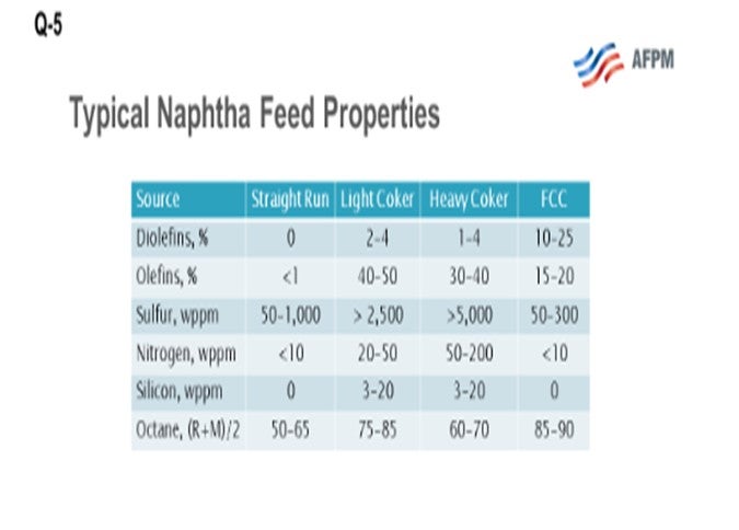
This question asks about the fate of coker olefins and coker naphthas. What we are looking at here are the three coker product streams, which include coker LPGs (liquefied petroleum gas), your C3s(propane/propylenes) and C4s (butane and butylenes), and light and heavy coker naphthas, which must be further processed before they can be blended or sold into the gasoline pool. Coker products are really a challenging feedstock. They are rich in sulfur, nitrogen, olefin, and diolefins and contain other contaminants including arsenic and silicon. What I have provided for you here on the slide is a comparison of a typical straight-run naphtha and typical cracked refinery naphthas, light coker naphtha and heavy coker naphtha, and FCC naphtha. What you can see is that there is significantly more sulfur and nitrogen, and also some other contaminants including silicon and arsenic, in the cracked naphthas. However, the octane is relatively good, especially in the light coker range.
The coker LPGs typically get blended with the FCC LPGs, both in a common or a separate gas plant. They are then upgraded to motor fuels in the same manner as FCC olefins: either through an alkylation or Polynaphtha™ process. Alternatively, the olefins might be recovered through fractionation and sold as chemical feedstock. When you co-process LPGs with existing equipment designed to process the FCC, C3s, and C4s, you need to pay particular attention to the potential for arsenic or arsenic contamination.
Both the light and heavy coker naphtha contain diolefins and olefin compounds in relatively high levels compared to other refinery naphthas. The presence of olefins makes the streams particularly difficult to treat in a conventional naphtha hydrotreater. Also, they are very high in sulfur and other contaminants. Diolefins can form gums when heated, resulting in fouling in the feed effluent exchangers. Olefin saturation has a very high heat reaction, resulting in large reactor exotherms. So, if your unit is not designed for high exotherms and severity, it becomes very difficult to treat coker naphtha in a standard straight-run naphtha hydrotreater, especially when you start to process a significant percentage of coker naphtha which may require a quench between reactor beds.
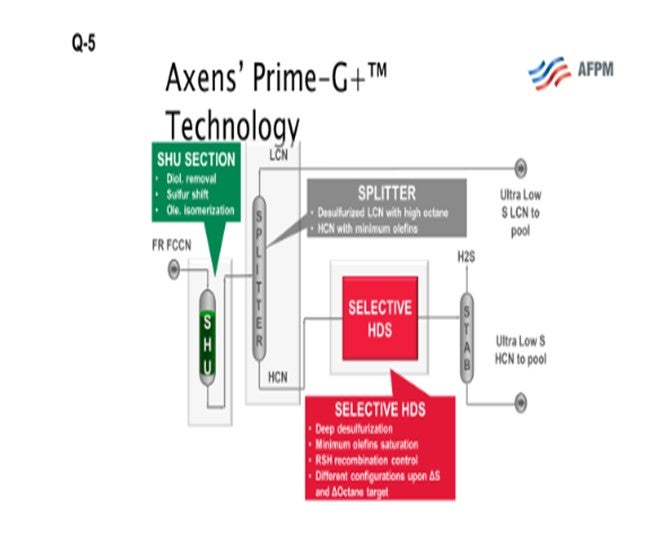
As I mentioned earlier, the high-octane value of the light coker naphtha makes it a good stream for blending into premium gasoline if the octane can be retained during desulfurization and is therefore a good fit for a selective hydrogenation unit, or SHU. The SHU will selectively saturate the diolefins, eliminating the potential for gums while preserving the high-octane olefin. Nearly all the light mercaptans, as well as a substantial portion of the light sulfides such as dimethyl sulfide (DMS), are converted to heavy sulfur compounds. The light naphtha is, therefore, functionally desulfurized and can be split out. If you look at the next slide, you will see an SHU process flow diagram. The naphtha flows through the SHU reactor where the diolefins are saturated and the light mercaptans are “shifted” to heavy sulfur compounds. The SHU reactor product then flows to a splitter where you can remove the light coker naphtha (LCN). This LCN can then be sent to a gasoline blending as a low sulfur component. The heavier portion from the splitter bottom, which includes most of the sulfur after the sulfur shift, is sent downstream to be desulfurized in a selective HDS (hydrodesulfurization) unit. The heavy coker naphtha, which commonly includes dimethyl disulfides, could alternatively be treated in a conventional naphtha hydrotreater and then sent to a catalytic reformer to recover the octane.
The heavy coker naphtha can be a burden for the conventional hydrotreater unit (NHT), especially if the NHT is designed for straight-run materials, as previously mentioned. Coker naphthas are really quite challenging feedstocks because they are laden with impurities and rich in sulfur and nitrogen. The high impurity loads, and more difficult desulfurization and denitrification loads can make this feedstock particularly challenging because typical straight-run naphtha hydrotreaters are not designed to provide sufficient severity. They are typically designed for lower pressure. They do not have the catalyst volume necessary to achieve the target cycle exit you might desire.
Alternatively, the heavy coker naphtha can be processed in the FCC gasoline selective hydrotreater, but with fewer synergies as compared to the light coker naphtha. Depending on the refinery configuration, co-processing of heavy coker naphtha with FCC gasoline can be practical when using Axens’ Prime-G+™ technology. Axens has successfully demonstrated this application in multiple refineries while maintaining normal unit cycle lengths.
JEFF BRAY and CHRIS ANDERLE (Honeywell UOP)
Coker C3/C4 olefins are usually processed with FCC olefins so that the value of the olefin content is captured. If there is no FCC, these olefins would be hydrotreated and routed with LPG. The coker naphthas (both light and heavy) are typically routed with the straight-run crude naphtha and hydrotreated in the naphtha hydrotreater. Coker naphtha does have olefins that have to be saturated in this unit, as well as having higher nitrogen and sulfur levels; therefore, the NHT (naphtha hydrotreater) requires a more robust unit design. The olefins will generate an increased exotherm that the unit design needs to accommodate to avoid mercaptan recombination. The dimethyl sulfides and disulfides are among the slowest reacting compounds removed in naphtha hydrotreaters, but they can be treated effectively if there is sufficient catalyst volume and pressure, producing naphtha that meets the low sulfur levels needed for reforming or blending. Where naphtha hydrotreating capacity is not sufficient to process this effectively, an alternative is to send it to diesel hydrotreating units. One issue with this approach is that the unit’s separation section needs to be able to recover the naphtha from the diesel. Most coker naphtha is processed in naphtha hydrotreaters. Once hydrotreated, coker light naphtha would go to the same destinations as the straight-run light naphtha including isomerization, gasoline blending, or naphtha sales. The heavy naphtha could go to reforming, gasoline blending, or naphtha sales.
Year
2016
Process
Question 6: What is your experience with having a vent depropanizer off-gas unit in order to manage tower pressure, and what might be the cause of and solution to the problem?
PHILOON (Honeywell UOP)
The typical and probably most obvious driver for the need to vent from a depropanizer column is the presence of Non condensable gases. Most commonly, this is ethane and ethylene that come in with the feed. The need to vent is more common in C3/C4 alkylation units as opposed to C4units. Even though the feed GC (gas chromatography) may show zero level of C2s in the feed, the limits of the analysis method may mask the presence of a significant, or at least notable, quantity of ethane and ethylene. Another possible Non condensable that may be present is nitrogen gas. This can be from the gas used to blanket fresh asset storage drums from some types of pump seals or other sources. The nitrogen is soluble in the acid, or it could break through when loading acid into unit. C4 alkys that get too many C3s in the feed may also have pressure control issues that can be ameliorated by venting. The C3 and C4 alkys have pressure problems if too much C3 material is allowed to accumulate in the unit. Another consideration is the overhead condensers. Exceeding the duty of these exchangers will raise the receiver temperature and, therefore, the column pressure. The elevated temperature can be a result of exchanger fouling or cooling water issues or from factors such as over stripping on the HF propane stripper.
KLEISS (Valero Energy Corporation)
The causes of frequent venting, as Steve mentioned, are typically insufficient condensing of propane or just too many non-condensables in the feed. Venting of the depropanizer can get expensive, as the vented gas is typically about 50% HF. If the propane is not condensing, cooling water flow and temperature could be the problem. Operating at higher isostripper pressure may also limit the venting. Most often, frequent venting is the result of noncondensables in the feed. This condition has happened at some or our refineries. The transfer of feed streams, both olefin and isobutane, with nitrogen or fuel gas should not be done. A Best Practice is to transfer isobutane and olefin by pump. Moving isobutane with fuel gas was an issue at one of our refineries. Routine GC analysis on the purchased isobutane to ensure light components, like ethane, are not too high is also a Best Practice. Typical units can generally tolerate a maximum of about 0.5% of C2 relative to the amount of propane in the feed. For example, if there is 10% propane in the feed, only 0.05% C2 can be tolerated. Adjusting the vapor flow in the HF stripper to maintain 30to 33% of the column feed will allow around 1% C2sto go out the bottom of the HF stripper. Over stripping will cause C2sto accumulate in the overhead. However, if the light material is methane, CO2, or nitrogen, it will need to be vented.
RON GATAN (Honeywell UOP)
Just a small comment about noncondensables. Moving up to the cat, even something as simple as tweaking the vapor-to-liquid ratio on the feed of the stripper in the gas condenser so that it is increased, as well as increasing the feed temperature, can result in dramatic improvement without getting rid of noncondensable to the alky, which I have seen.
RON GATAN (Honeywell UOP)
The typical and probably most obvious driver for the need to vent from the depropanizer column is the presence of a noncondensable. Most commonly, this noncondensable is ethane and ethylene that come in with the feed. This contamination is more a concern with C3/C4 alkylation units as opposed to C4units.Even though the feed GC may showa “0” ppm level of C2s in the feed, the limits of the analysis method may mask the presence of a significant quantity of ethane and ethylene.
Another possible noncondensable that may be present is nitrogen gas(N2). This can be from gas used to blanket fresh acid storage drums, from some types of pump seals, or from other sources. N2is soluble in the acid, or it can “breakthrough” from the storage tank when loading acid into the unit.C4 alkys that get too many C3s in the feed may also have pressure control issues which may be ameliorated by venting. Even C3/C4 alkys may have pressure problems if too much C3material is allowed to accumulate in the unit. Another consideration is the overhead condensers. If we exceed the cooling duty of these exchangers, the receiver temperature and the column pressure will increase. This problem can be as a result of exchanger fouling or cooling water issues or from factors such as over stripping on the HF/propane stripper.
Year
2016
Process