Question 58: What issues have you seen in your wastewater treatment plant caused by crudes containing biocides? If so, what parameters have you established to control these effects?
BRADEN (NALCO Champion)
Biocides: Typically, the upstream group wants to kill bugs and the downstream wastewater treatment plant wants to keep them alive. So, you have bacteria in light tight oils, as well as in the oil sands, during crude oil production. The upstream group uses a biocide to prevent the sulfide-reducing bacteria to produce H2S, and the dosage is usually between 25 to 500 parts per million. The injection can either be slug feed or a continuous feed. Most common oilfield biocides are glutaraldehyde, tetrakis hydroxymethyl phosphonium sulfate (otherwise known as THPS), quat (quaternary) amines, and 2,2-dibromo-3-nitrilopropionamide, which is DBNPA, as well as a variety of other eracids. The biocides fed in the oilfield typically do not reach the refinery. They are oxidized out and reduced down, so they do not play a role in refining.
At the refinery, we are seeing biocides being added to the crude tanks to inhibit bacteria growth. Sulfate-reducing bacteria will produce H2S leading to downstream corrosion issues. Typically, a water-soluble biocide is used. It may be a peracid or THPS that is used there. The type of biocide used is based on consultation with the refinery’s chemical vendor. Sometimes groups within a refinery do not like to communicate with one another. But when you put this program in place, the tank farm has to be in contact with the wastewater treatment plant. And when you are drawing down the water from the tank, you must let the wastewater treatment plant know when the drawdown is scheduled.
In the wastewater treatment plant, you have a primary system to separate the oil from the water. The secondary system is where the bacteria will work to remove the water-soluble hydrocarbons, ammonia, and phenols out of the wastewater, thereby allowing the wastewater plant effluent that is discharged to meet the stringent and strict requirements by the state and federal government. The wastewater plant will have to know what types of contaminants are in the washwater plant influent, particularly if a biocide is being used at the tank farm. It is best to use a stepwise approach, such as drawing down the tank using three or four steps, to avoid overwhelming the biological system and killing the bacteria needed to reduce the soluble organics. The wastewater treatment plant will need to develop a monitoring and respiratory program to determine if the dissolved oxygen in the secondary system is being maintained at a minimum level.
JOE PRINCE (Amec Foster Wheeler)
Since these compounds are designed to inhibit the biodegradation process, as well as other methods, prevention of negative impacts on the treatment plant can be accomplished using the following techniques:
-
Maximum equalization of desalter effluent to minimize the concentration of these compounds entering the treatment plant.
-
Increased Activated Sludge System Mean Cell Residence Time by either adding additional aeration capacity or by using fixed-film media (e.g., Kaldnes, hydroxyl, etc.) to promote biomass acclimation by providing longer biomass residence time. Fixed-film media has similar benefits by adding surface for anaerobic growth, as well as a level of “shock” resistance.
-
Increased or modified chemical usage or chemical modifications in upstream API/DAF equipment designed to promote precipitation/flotation of the biocide(s).
MICHAEL BRADEN (NALCO Champion)
With the production of crude oils, particularly in the opportunity crudes like LTO (light tight oil) and oil sands, the same contaminants that are a challenge to the refinery also impact the wastewater treatment reliability. These contaminants are not only found in the crude oil, but also the crude will have chemical additives such as biocides, demulsifiers, hydrate inhibitors, corrosion inhibitors, and other additives. These chemical additives can cause issues in the desalter applications resulting in oil carryunder and emulsion stabilization to other downstream processes.
As this question concerns biocides in particular, the short answer is that biocides used in the upstream applications normally do not cause issues in the refinery’s wastewater treatment plant (WTP). As for solubility, almost every oilfield biocide is water-soluble as that is where the microbial issues reside in oilfield applications (the water phase).
In the oilfield, dosages of biocides are all over the board, depending on the application, geography or the extent of the microbial contamination. But in general, most biocide dosages will be applied as a batch treatment somewhere in the range of 25 to 500 ppm active (although it can go up higher in some applications). Most of the biocide used will be consumed or will breakdown long before it gets to the refinery.
The most commonly used oilfield biocides are glutaraldehyde, tetrakis hydroxymethyl phosphonium sulfate (THPS), quaternary ammonium compounds, 2,2-dibromo-3-nitrilopropionamide (DBNPA), isothiazoline, chlorine dioxide, peracetic acid, and several different preservatives that are formaldehyde releasers.
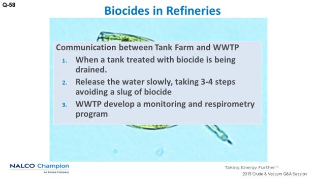
However, biocide usage is being discussed and used to control bacteria growth in the refinery’s crude holding tanks. The key to using the biocides is good communication between the tank farm operators and the wastewater treatment plant (WWTP) personnel including.
-
Knowing when a treated tank is going to have the water drained, so the WWTP can be notified and alerted;
-
Releasing the water from the tank slowly, as in three or four steps, so the WWTP does not get a onetime slug of the biocide; and,
-
Recommending to the WWTP that it should develop a comprehensive monitoring program and possibly respirometry to mitigate any potential issues.
Generally speaking, the issues with unconventional crudes typically fall into the categories of “high” and “variable” loading to primary treatment due to the high solids crudes, like the oil sands or shale plays; contaminants inherent in the crude, naphthenic acids which do not negatively impact biological system but result in final effluent toxicity; or, additives that are introduced during the production of the crude, H2S scavengers for the shale plays.3 Additionally, the refiner may have to introduce an additive during desalting, organic acids as an example, to remove a particular contaminant to prevent overhead or desalting issues.
Contaminants like phenols are common of all crudes, not necessarily more prevalent in the typical unconventional crudes, and readily biodegradable in the appropriate environment in an activated sludge system. Of course, we are only starting to understand the contaminants in these crudes; so again, Nalco Champion recommends a comprehensive review of the mechanical, operational, and chemical operating programs of the wastewater treatment plant to prevent any downstream consequences; or worse, to the refinery production curtailment.
With that said the same contaminants that challenge refinery operation also impact wastewater treatment reliability. With respect to the heavy bitumen crudes of the Canadian oil sands, tight, hard-to-resolve emulsions can result in oil undercarry if not properly treated in the desalter. Even with optimum desalter performance, the higher level of solids inherent in these crudes increases the loading to the WWTP, which can impede the plant’s primary treatment facility from effectively removing oil and solids prior to discharge to a biological treatment plant. Finally, the oil sands hydrocarbons contain significant levels of naphthenic acids and other high molecular weight organic acids which can be extremely toxic to aquatic organisms.4 Tight oils of the U.S. shale plays are also high solids crudes yet have the added complexity of variability between shale plays and shipments. Various additives are required to extract these crudes from their source and can challenge the biological treatment plant’s ability to meet effluent requirements.
OIL SANDS HYDROCARBONS
The majority of the world oil reserves are controlled by national governments with only 20% accessible to the private sector; the Canadian oil sands comprise 56% of that fraction.5 Located in three primary locations in Northern Alberta, the Canadian oil sands are a combination of sand, water, clay, and bitumen, a heavy viscous oil. The first separation of the oil from the deposit was performed in 1929 by Dr. Karl Clark using a hot caustic wash. The method, known as the Clark Hot Water Extraction Process, remains the most common method for recovering bitumen from the oil sand deposit.6 Once extracted, the bitumen must be mixed with a diluent to facilitate flow, and it is this practice that increases the tendency to form stable water in oil emulsions during the desalting practice. Although advances in heavy oil demulsifiers have minimized the potential for oil undercarry, other techniques used to enhance the crude unit performance (namely, changes in desalter mud-wash procedures and washwater rates) only exacerbate the negative effect to wastewater treatment.
High Solids
Heavy oil demulsifiers are effective at reducing the water, salt, and solids content from the crude but produce effluent brine that is very high in total suspended solids (TSS). If operational changes are not made in the primary treatment plant to compensate for the higher solids loading, poor oil removal efficiency in the API – and to a lesser extent, flotation equipment – can result.
Naphthenic Acids
Although ubiquitous in all petroleum, naphthenic acids (NA) are more predominant in heavy crude oil sources.7 The term “naphthenic acid” refers to a complex group of carboxylic acids that are relatively insoluble in water at neutral pH levels, yet which will partition to the water phase under alkaline conditions. Although NAs are not inhibitory to a wastewater treatment plant’s biological system, they are extremely toxic to some aquatic life at very low levels.8 They only represent a fraction of the wastewater influent chemical oxygen demand (COD) and are typically not detected with conventional activated sludge monitoring techniques. Therefore, extreme focus must be directed to the operation and control of the wastewater treatment plant’s primary and secondary treatment systems to avoid effluent toxicity.
Light Tight Oils (LTOs)
Unlike the unconventional oil sources in Northern Canada, the tight oils of the United States are light crudes that are found in reservoirs with low permeability. Although not limited to shale, the majority of the oil is located in shale and is therefore often referred to as shale oil or a shale play. The highest concentration of production and reserves are located in the Bakken play in North Dakota and Montana and the Eagle Ford play in Texas. Similar to the heavy Canadian crudes, tight oils may contain significant quantities of solids and can be even more challenging due to the wide variations in characteristics between plays. Also, surfactants are added during production and can result in tight emulsion and oil undercarry in the desalter. The effects to wastewater are the same as those highlighted for Canadian crudes, so the mitigation techniques previously discussed (chemical treatment, operational changes, automation, etc.) are successful during the production of tight oils.
Other commonly used additives in tight oil production are hydrogen sulfide (H2S) scavengers. To date, the consequences of the scavenger have not been significant enough to cause catastrophic upsets in any of the wastewater treatment plants surveyed. That is not to say, however, that a threat does not exist.
H2S Scavengers
Triazine compounds are frequently used to react with the hydrogen sulfide generated during the production of the tight oils. Work by Gardenhire in 20099 demonstrated that the water-soluble reaction products, monoethanolamine (MEA) and methylamine (MA) of the most common scavenger chemistries, are biodegradable up to levels as high as 200 ppm. The overall BOD and nitrogen loadings, however, will increase. It is, therefore, important to implement a comprehensive monitoring program to ensure system health and effluent quality.
Another situation becoming more prevalent in refineries processing shale oils is acid addition in the desalter to manage pH levels and prevent oil undercarry in the brine. The acids, low molecular weight organic acids, are readily biodegradable and often translate to settling issues in the biological clarifier. The settling issues may be related to either filamentous or viscous bulking or both. In the case of filamentous bulking, chemical treatment can alleviate some of the issues; however, chemical treatment has minimal success on viscous bulking conditions. It is, therefore, desirable to correct the issue starting with a comprehensive microscopic analysis which includes filament identification to identify the source of the settling problems. Depending upon the root cause, the mitigation approach could be as simple as additional additives or more complicated, such as infrastructure modifications; namely, alterations in recycle or influent configurations.
Year
2015
Process
Question 59: What is your experience with hot preheat train and heater fouling attributed to waxy crudes? What methods can be used to identify fouling that is specific to wax in crudes?
WEBER [Marathon Petroleum Corporation (MPC)]
MPC has seen an increase in hot train fouling when processing light tight oils, which tend to be more paraffinic than conventional crudes. The leading theory is that, combined with conventional or heavy bitumen crudes, the crude mix experiences asphaltene destabilization. The asphaltenes then precipitate on heat exchanger surfaces, decreasing effective heat transfer and increasing pressure drop. We have done a few trials with an asphaltene stabilizer combined with an antifoulant; however, the results of that trial were inconclusive.
In another case, we were actually getting ready to start a chemical trial when the fouling leveled off, so we did not move forward with it. The point is that the fouling has been very unpredictable. We have not been able to correlate it to a specific crude or a specific combination of crudes, but the theory of asphaltene destabilization is well-documented within industry.
A second theory has to do with the deposition of heavy waxes; and then, the subsequent thermal cracking causing fouling in the preheat train. If that mechanism was suspected, we would analyze the foulant for the hydrogen-to-carbon (H/C) ratio. Obviously, a higher hydrogen (lower H/C) ratio will indicate a more paraffinic foulant. We have seen waxy fouling in the cold train, but we have not confirmed that as a fouling mechanism in the hot train.
BRADEN (NALCO Champion)
Paraffin wax is, of course, a long-chain-saturated hydrocarbon. The hydrogen-to-carbon ratio is typically 7:1 by chemical element analysis, which is one of the techniques Nalco Champion uses to identify the origin of the deposit. The reason is that it is on the hot side, not on the cold side. We expect waxier crude foulant in the cold-side preheat rather than in the hot-side preheat. So, Nalco Champion would want to make sure that it is waxy crude on the hot side and that the refinery obtains a sample of the deposit from the heat exchanger cleanout. Sometimes, if the refinery lets the heat exchangers cool down, the waxes will come out. Some of the waxes can have a melting point up to 90°C (194°F).
So first, identify the waxy crudes by doing a SARA analysis, which measures the concentration of saturates, aromatic, resins, and asphaltene fractions in the deposit sample. The carbon distribution is measured by gas chromatography. These studies will provide information about the crude and the percentage of the crude chain lengths and will provide information on the types of deposits are formed in the heat exchangers when using these types of crudes. I know the Bakken crude can have about 2% (and greater) of C35 as we measured it. So you do have some long-chain waxy crudes in the light tight oils. It is just a matter of identification.
MIKE ADKINS (KP Engineering, LP)
You mentioned a lot about the light tight oils. I am wondering if anyone has any experience with the yellow, black crudes out of Utah.
BRADEN (NALCO Champion)
As was mentioned in yesterday’s Keynote Address, the light tight oils, particularly Bakken, can be anywhere from clear to cloudy to black, depending on where they are produced. We find that in shipments, the wax comes out, particularly in railcars. There is a research project that is trying to solve that issue.
In the refinery, my personal experience is that you have wax deposits in the cold preheat going to the desalter. Trying to develop a program for wax deposits in the pre-heat exchangers (pre-desalter) is difficult; because normally for upstream applications, the crude is heated past its melting point. A paraffin-stabilizing agent or paraffin inhibitor is added; however, in order for the inhibitor to be effective, it must be above the melting point. So, you are trying to develop chemical programs to disperse the wax crystals and prevent the wax crystals from depositing on the walls of the pipeline. So it is an issue that we do see in the cold preheat, and we are working on it.
SAMUEL LORDO (NALCO Champion)
For the black and yellow wax, really the biggest issues we have seen are actually from what looks like upstream additives – bromides, in particular – that are coming out in the hydroprocessing area as bromic chloride salts. So that is a little different. Typically, we worry about ammonium chloride. Those two crudes tend to have bromine-type contamination, so you do see some issues with them.
On the heater fouling, what we now see, particularly in the crude heater – which is unusual in the refining world – is that run-lengths are going from three to four years down to three months and that they have to pig the furnace tubes repetitively.
SALVATORE TORRISI, JR. (Criterion Catalysts & Technologies)
Yes, it is a real technical term, “pig”.
SAMUEL LORDO (NALCO Champion)
We have identified the foulant as a formation of polycyclic aromatic material. This is directly related to the LTOs, so it is a little different theory than the theory of paraffin cracking and reforming. It is more of a molecular rearrangement, which makes more sense since nature likes to keep it simple. There are some effective mitigating techniques for this fouling mechanism. We observe fouling starting when the refiners start to process light tight oils at greater than 80%.
DENNIS HAYNES (NALCO Champion)
There has been some wax-like material that has fouled preheats. It is not common, yet it has occurred and seems to be more frequent than in the past. If the suspect whole crude is available, it may be tested for insoluble material, then thermally stressed in an autoclave and then re-tested to determine if the non-asphaltene material became insoluble due to thermal stresses and indicative of potential fouling tendency. If a sample of the foulant material is available from the process, it can be analyzed H/C ratio, solubility testing, etc. to determine if it is an asphaltenic material or more wax-like.
GARY HAWKINS (Emerson Process Management)
Light tight oils are an example of crudes with a high paraffinic content and high filterable solids [200 to 300 ppb (parts per billion)] that are recognized as having a high propensity for fouling in the cooler section of the preheat train and also for introducing instability of the asphaltene phase which results in increased fouling in the hotter sections of the preheat train. Refiners are investing in more pressure and temperature measurements around the heat exchangers to gain better visibility to the fouling as it happens, and the advent of wireless field devices has lowered the capital cost hurdles of adding instrumentation.
RALPH WAGNER (Dorf Ketal)
The SARA analysis of the deposit, the H/C ratio of each component, and elemental analysis will help characterize the extent to which paraffinic waxes are a component of the deposit. Testing the solubility of the deposit in a paraffinic solvent will further quantify the extent to which wax in the crudes is a root cause of the fouling. Chemical and blending strategies are available to mitigate the problem.
JOHN WEBER [Marathon Petroleum Corporation (MPC)]
MPC has observed higher fouling rates of heat exchangers in the hot train correlated with an increase in processing light tight oils. These crude oils tend to have a higher wax content and lower asphaltene content than conventional crudes. Within the industry, two proposed theories for this elevated fouling are asphaltene destabilization and heavy wax deposition.
Asphaltene destabilization has been well documented within industry and is thought to be caused by crude incompatibility between the LTOs and conventional oils and/or heavy bitumen crude types.
Another theory involves the deposition of heavy/high melting point waxes in the hot train. The waxes are thought to thermally crack, then polymerize, and subsequently foul exchangers and heaters. Higher H/C ratios in the foulant would be expected from this fouling mechanism versus asphaltene fouling. While paraffin wax fouling in cold train has been well documented, this fouling mechanism has not been confirmed in the hot train within MPC’s experience.
MICHAEL BRADEN (NALCO Champion)
Paraffin wax produced from crude oil consists primarily of long-chain, saturated hydrocarbons (linear alkanes/n-paraffins) with carbon chain lengths of C18 to C75+, having individual melting points from 40 to 70°C (104 to 158°F); and in some cases, up to 90°C (194°F).
High melting waxy crudes can cause deposits in the cold heat exchangers (prior to the desalter unit) and have been found in the desalter rag layer when the desalter temperature is not high enough to melt the wax.
Waxy crudes are identified by having an H/C ratio of 7 or less as determined by mass spectrometry. (As an aside, gums can have an H/C ratio of 7 to 12; resins have an H/C ratio of 8 to 9; asphaltenes have an H/C ratio of 9 to 12; an H/C ratio of 12 to 17 is oxidized and/or dehydrogenated organics; and coke has an H/C ratio of >17.)
Identification of waxy crudes begins with a current crude assay, SARA analysis and carbon number distribution by gas chromatography (GC). This will provide information about the crude and the percentage of carbon chain lengths of the crude.
Year
2015
Process
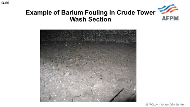
Question 60: Please describe your experience with the occurrence of phosphorus and barium fouling in the distillate section of the crude tower. What steps have you taken to identify and mitigate the problem?
WATTS (LyondellBasell Industries)
This slide contains our legal disclaimer. I am really not going to cover it in a lot of detail. [Laughter] Just use your own judgment.
I know this topic generated a lot of discussion in our Hydrotreating session yesterday. I am mainly, obviously, going to focus on the crude side of it. I will start by saying that basically, it starts with a process to analyze processed crudes for impurities to manage and minimize fouling coming from salts, asphaltene precipitation, and other impurities.
Corrosion: Obviously, we look at TAN in the crude, organic chlorides, amines, and ammonia. We do not always do a full analysis of the crudes we are processing day in and day out, since we have a long history on those crudes. But when we are looking at new crudes, we do a more detailed analysis.
We also look for catalyst poisons mainly to make sure we do not have high levels of silica, phosphorus, arsenic, and other materials that would cause accelerated or loss of catalyst life. And then, we look at the downstream impacts on those units. But overall, our goal is obviously to manage equipment reliability and catalysts between turnaround cycles.
Last year, we took a short outage to replace a piece of equipment on one of our crude units. We were a little over five-and-a-half years into the run since the last turnaround cycle. When we started up after the outage, we saw that the top section of the crude tower dP (differential pressure) had increased to five pounds. Before the outage, it was two pounds, and that was for the top 20 trays of the crude tower. We had experience with trays fouling prior to this outage. When we would shut down the unit for turnarounds, we would see that the top six to eight trays had some fouling from salts that deposited on the trays.
Next, we did a tower scan and also a more detailed pressure survey which showed that the liquid had started to back up in the tower just below the kerosene pumparound section. As I said, that is around Tray 20. So, as we were scanning the tower, we basically adjusted the liquid loading in the tower. We dropped the pumparound and the top reflux. Once we did that, we saw that the pressure drop returned to a normal range. The tower was no longer flooding.
Actually, prior to the outage, we had noticed an increase in fouling in our kerosene pumparound exchangers. We talked to some of the operators after we saw the increase in the tower top pressure drop. We also had some issues with valves closing when they were isolating the kerosene pumparound exchangers. So, we did an analysis of that stream; and basically, we saw a combination of corrosion products and hydrocarbons. We also saw trace levels of phosphorus as high as 800 ppm (parts per million). As I said, this occurred in April of 2014. We have continued to run the crude tower.
To manage this increased pressure drop and fouling, we have adjusted our kerosene pumparound. Before April of last year, we typically ran that pumparound at a rate of 1,300 barrels per hour or higher. Currently, we are running the pumparound at the minimum, which is 750 barrels per hour. So obviously, our kerosene production has dropped off. We have also lowered our top reflux in the tower and adjusted the heater outlet temperature and stripping steam to the tower to reduce the vapor load for certain crudes.
We have a planned outage for the first quarter of 2016 as it will have been a little over seven years since the last turnaround. We worked with a company to redesign the trays, so we plan to replace the trays. During the outage, we will also be able to verify the fouling.
BRADEN (NALCO Champion)
We have conducted deposit analysis on samples in the jet kero (kerosene) trays and found that the phosphorus component in the deposit, along with the iron and sulfur. The phosphorus usually comes from an upstream additive that is used in the fracking aspect of water-sensitive clay formations. They use a mono- and diphosphate ester to help with the fracking process that can be complexed with an inorganic material and removed from the crude oil. During the manufacturing of the mono- and diphosphate esters, a triphosphate ester is also formed which is oil-soluble and cannot be complexed. The triphosphate ester is the material coming in with the crude once it passes through the desalter. But once it gets into the heat exchangers into the towers, it starts decomposing. It starts hydrolyzing to phosphoric acid. So essentially, phosphoric acid distills up tower, deposits onto the tray, and then precipitates at the jet kero trays. When the phosphorus-containing deposits increase in size, the deposits then begin closing the holes in the trays.
Some refiners will replace the trays with trays containing larger holes, therefore allowing you to get more flow in the jet because the jet fuel has a phosphorus spec. Essentially, we try to mitigate the phosphorus from distilling up the tower by injecting a chemical additive that complexes the phosphorus to keep it into the resid fraction and does not distill up the tower. So, if you want to know a little more about that, contact your chemical vendor.
WEBER [Marathon Petroleum Corporation (MPC)]
We have had some practical experience. The picture here shows phosphorus fouling of one of our crude towers. This is in the kerosene section again. The first time we experienced it in 2011, we went into a tower for turnaround and found fouling in the kero section, with none above or below. It had not caused an operational problem, and we actually did not analyze foulant that was on the tray at that time.

At another MPC refinery, the crude unit was reduced, for economics, for roughly a month. When an attempt was made to return the unit to full rate, flooding was observed in the kerosene section. We were referred to the Canadian Crude Quality Technical Association (CCQTA) which immediately said, “Oh yes, you have phosphorus issues.” After further discussion, it was discovered that CCQTA has extensive experience with phosphorus contamination. Their website indicates that since 1995, they have had a project on phosphorus fouling and have worked with some of their producers to help minimize it.
A similar incident occurred at a third refinery. One of the remedies we have implemented is the installation of fouling-resistant, fixed-valve trays in the kero section. In refineries that still have floating valve trays, we try to keep vapor traffic up in the kerosene section. We have found occasions where the valves were found stuck open; but fortunately, they did not cause an operational issue. It is when we got lower rates and lower velocities that the valves became stuck closed and caused flooding problems. We have also had experience with barium fouling in the wash section of the crude tower. This picture shows an example of that problem. The solution for this issue was also to install foul resistant, fixed-valve trays.
NAGASHYAM APPALLA (Reliance Industries Ltd.)
Is there an industry-accepted limit of monitoring the phosphorus in the crude oil? If so, does anyone distinguish the differences between volatile and non-volatile phosphorus?
WATTS (LyondellBasell Industries)
I want to echo some of what John said. I did quite a bit of research on this and know that it is not a new issue. I think the slides I found were from the mid-1990s, and the specification levels I saw were 1 to 1.5 ppm. But based on our working with our lab, we have not seen a detectable level of phosphorus on the crudes we have analyzed. We have not traced it back to a crude source.
BRADEN (NALCO Champion)
In our experience, the phosphorus compounds enter the refinery via the crude and normally come in slugs because of the fracking issue; and therefore, it can be up to 50 parts per million when you get a slug of phosphorous material. But in our measurements of it, it is normally 1 to 3 ppm. We have run that by ICP (inductively coupled plasma) analysis. So it is normally very, very low if it is in there. But sometimes, you do get slugs. Then when do you catch a slug? When do you see that? You just see the results of the slug coming through. It is hard to pick up.
NAGASHYAM APPALLA (Reliance Industries Ltd.)
What is the industry’s experience on the cause of this fouling when using high temperature corrosion inhibitors in atmospheric tower?
SAMUEL LORDO (NALCO Champion)
The inhibitors that are used for high temperature treatment are not really part of that particular description. As Mike indicated, those are triester compounds which come in with some of the fracking gels that are used in Western Canada or in clay formation-type crudes where they are water-sensitive. In the lower 48 though, there is no fracking with phosphorus-based gels. Now we are targeting to look at phosphate esters being used for scale control and corrosion inhibitors.
I looked at one complete year of a refinery’s crude tracking where they analyzed for phosphorus the entire year on each batch that came in. Most of it was in the 1 to 3 ppm range; except in November, it shot up to about 10 to 15 for a one-month period. And then, it came right back down. During that timeframe, their tower had some issues which have not yet been resolved. So they will have to come down and clean it. But as far as the inhibitors go, most of them do not cause a problem. If you overtreat, then yes, you can have some issues.
PRICE (Fluor Corporation)
Just a comment to the Mr. Appalla from Reliance: If you have not visited the CCQTA website, I recommend that you do because it contains is a lot of information about lab methods that might be helpful.
NAGASHYAM APPALLA (Reliance Industries Ltd.)
Yes, but the CCQTA only talks about the phosphorus coming from the Canadian crudes. Suppose you are not processing Canadian crudes. What are the other sources of it?
HAROLD EGGERT (Athlon Solutions)
It is an odd question when you say barium and phosphorus in the same sentence. Why would you pick those two particular elements to examine? Like Sam, and I think the panel, have mentioned, not all phosphorus is going to end up fouling your trays. It is always coming in at a low level. Some of it is benign phosphorus, and some of it will contribute to tower fouling. What is currently being used – and the reason the barium came up – is that the phosphorus causing some of these problems is injected to prevent barium sulfate scale upstream. It is a scale inhibitor. If you see barium and phosphorus, chances are it is from the production chemicals. The barium used to be called NORM: Normally Occurring Radioactive Material. That is why we are looking for phosphorus and barium. It is the combination of the two that sends up a red flag.
JEFFREY ZURLO (GE Water & Process Technologies)
Just to clarify, you are right. The CCQTA talks about phosphate esters from Canadian crudes. One of the test methods they have on their website specifically identifies volatile phosphates. The CCQTA test separates the volatile phosphorus components from just the general phosphate components by performing a distillation on the whole crude and analyzing the middle distillate cuts. Although the CCQTA work is done on Canadian crudes, the source of the crude oil really does not matter. What is important is if phosphate is in the crude; if it is volatile; and, if it can hydrolyze, complex, and form this fouling material. So, it is not necessarily the source but more the effect of what type of phosphate is in the system.
BILLS CATES (Hunt Refining Company)
If I understood the question, what Mr. Appalla is really asking is: Other than light tight oils, where are they finding crudes containing phosphorus? He just really wants to know what crude; he does not want to buy. [Laughter]
WATTS (LyondellBasell Industries)
I mentioned earlier that we have not traced it back to its source, at least in our refinery.
BRADEN (NALCO Champion)
The phosphate esters for the fracking are mainly coming from the Canadian side, the north coast of North America, and the south coast of Canada.
JESSICA NAQUIN (Valero Energy Corporation)
I have heard rumblings that the fouling would have less affinity for metallurgies. For example, if you have carbon steel or different variations of stainless trays or parts in the tower, sometimes the phosphorus fouling will not have the same affinity; so then, you will not have the same accumulation of the fouling in the tower. Does anyone have experience with those observations and any Best Practices?
WATTS (LyondellBasell Industries)
I do not have experience on the metallurgy. I would say that what we are doing is similar to what John said in that we redesign the trays to go to a fixed valve. So, we avoid the potential – if you turn down, increase, or shut down a unit – of your valve getting locked in place; that is, if you have a floating valve. Obviously, that changes your flexibility on how you can run the crude unit when you turn down rates.
PRICE (Fluor Corporation)
Once again, I am not an expert on this subject. Based on the experience of our clients, I think the jury is still out on the subject of phosphate fouling. People are finding, in some cases, that when they solve the fouling problem in their crude tower, the fouling problem migrates downstream to the exchanger. While exchanger fouling is not a good problem, it is solvable. If you can then install a bypass and if you have the ability to do online cleaning of that exchanger, it will help to mitigate the impact on your unit throughput.
RALPH WAGNER (Dorf Ketal)
Fouling in the distillate section of the crude tower due to phosphorus is rising globally. A primary likely cause is the result of phosphorus-containing chemicals used in oil exploration and production. However, in recent surveys, several of the fouled towers have employed naphthenic acid corrosion inhibitors which have contributed to the problem.
The corrosion inhibitors contain phosphorus, and most products are thermally unstable and contribute foulants to the system. A Best Practice is to use a thermally stable inhibitor containing a phosphate triester. This type of corrosion inhibitor can withstand processing temperatures and does not contribute to phosphorus fouling. By comparison, mono and diphosphate esters are prone to thermal degradation; products of decomposition contribute to phosphate fouling.
For barium, we have observed issues in desalters, preheat exchangers, and towers due to presence of barium in the crude. The presence of barium appears to depend on geographic location and how the well has been fractured. Bentonite clay used in oil well fracturing contains barium, and poorly fractured wells may allow this clay into the crude. Barium is not soluble in oil or water, and the small particle size leads to accumulation in the rag layer in the desalter. Steps to mitigate barium accumulation include the reduction of pH and the optimum selection of desalting chemicals and mechanical adjustments for minimizing rag layer.
JOHN WEBER [Marathon Petroleum Corporation (MPC)]
MPC has experienced fouling in the kerosene section of crude units at multiple refineries which has been attributed to phosphorous. The first documented occurrence was found in 2011 during inspection of the tower during a unit turnaround. A light crusty scale was found on the trays in the kerosene section with no fouling in the sections above or below. Although this scale was not analyzed, subsequent incidents support phosphorous as the culprit.
A second occurrence followed an extended rate reduction at another refinery. When the refinery attempted to return to maximum rates, they were limited by flooding in the kerosene section. The MPC Crude Quality Manager at the time had heard of similar issues and referred the crude technologist to the Canadian Crude Quality Technical Association (CCQTA). The CCQTA representative suggested phosphorous fouling as the potential problem based on experience with other refineries. An attempt to remove phosphorous with online chemical treatment showed some effectiveness, but the unit was ultimately taken down to clean out the fractionator concurrent with a planned turnaround. The valves on several trays in the kerosene section were found to be stuck closed, which caused the flooding issues in the tower (See Figure 1). Analysis confirmed phosphorous as a major component of the foulant. Similar fouling has been found in one other refinery on inspection, however the valves were stuck open versus closed and did not impact operation.
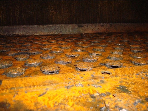
Figure 1. Example of phosphorous-induced tray fouling in crude unit kerosene section
The CCQTA website indicates that the group initiated a project in 1995 because of phosphorous-related fouling at three Canadian refineries. The source of the phosphorous was traced back to additives used in the production industry.
MPC has switched to fouling-resistant, fixed-valve trays in crude towers where phosphorous fouling is thought to be an issue. In addition, at a refinery where we have not been able to replace trays yet, efforts are made to keep traffic high in the kerosene section in the event of a rate reduction.
MPC has also experienced fouling attributed to barium at one refinery in the wash section of the crude tower (Figure 2). Fouling-resistant trays were installed to minimize fouling rate and extend time between cleanouts.
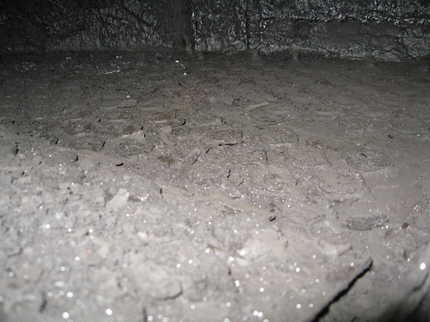
Figure 2. Barium fouling in wash section of atmospheric crude tower
MICHAEL BRADEN (NALCO Champion)
Deposit analysis of the jet/kerosene trays in the distillation towers has shown that phosphorus can be a component in association with sulfur and iron. The phosphorus usually results in the use of a chemical additive in upstream applications, such as a part of a corrosion inhibitor, or present in downhole fracking fluids. Phosphorus-containing additives are also used as fouling inhibitors for barium sulfate.
The downhole applications use mono- and diphosphate esters that can be removed by coagulation via inorganic chemicals. Unfortunately in the manufacturing process, triphosphate esters are also formed, are oil-soluble, and cannot be removed by the coagulation mechanism. Thus, the triphosphate esters move through the refinery’s desalters and are in the crude entering the distillation towers. At this point, the higher temperatures begin to hydrolyze the triphosphate esters converting to it to phosphoric acid, which then distills up the tower and condenses at the jet or kerosene sections. The acid reacts with the iron and sulfur causing corrosion to occur. Overtime, the deposit is large enough to block the holes in the trays. At this point, the tower needs to be shutdown to remove the deposit.
There are chemical additives which are used to complex the phosphoric acid generated and keep the phosphorus in the resid. Please consult your chemical supplier.
Another method to mitigate the fouling is to install trays with larger holes; although this will not decrease the fouling, it will lengthen the run time for the tower.
EDWIN WATTS (LyondellBasell Houston Refining)
It is important for refineries to have a rigorous program to analyze crudes, particularly new crudes, for impurities that will cause issues on the crude or downstream units. Recently, we experienced fouling in the kerosene section of one of the crude units. A sample from the kerosene pumparound exchangers showed a combination of hydrocarbons and corrosion products. There were trace levels of metals and phosphorous. We have made adjustments to unload the top section of the tower to minimize flooding, reduce pressure drop, and improve fractionation. We will verify the fouling mechanism during an upcoming turnaround.
MAUREEN PRICE (FLUOR)
Phosphorus originates mostly from secondary recovery processes and causes severe fouling in the jet pumparound (both trays and exchangers), jet product route (exchangers), and in the jet-diesel fractionation section. There have been problems with some Canadian and fracked crudes, as well. Fouling-resistant trays, such as PROVALVES, have been effective (at least in some cases) in alleviating the problem in the tower but have aggravated the problem in the exchangers. Bypasses permitting cleaning exchangers when the plant is running have been very useful, but beware of design conditions. It is difficult to predict the offending crudes as the amount of phosphorus is usually small in them. The deposits often show 10 to 50% phosphorus. However, one Southern California refiner who runs 20% Canadian crudes has no evidence of any phosphorus fouling. Barium fouling has been experienced by another client.
CCQTA has established a limit of maximum of 1.5 ppm volatile phosphorus after conducting research. Their website has a large amount of information available, including test methods.
Year
2015
Process
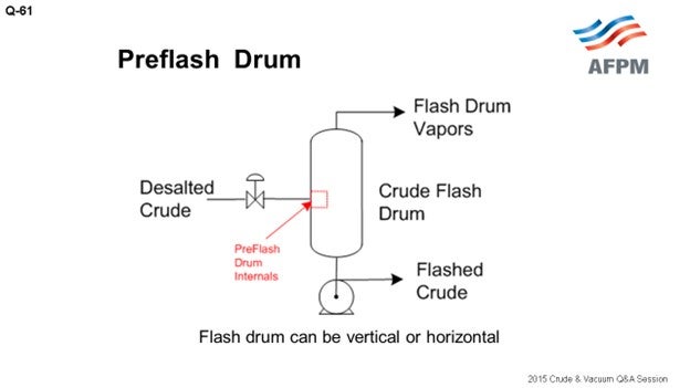
Question 61: What are the advantages and disadvantages of preflash/pre-topping columns in crude units in terms of operational flexibility to process different API crudes? Please comment on overall energy efficiency and reliability (corrosion).
ALLRED (Suncor Energy, Inc.)
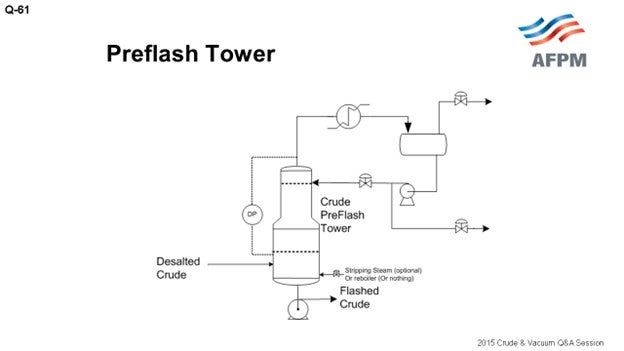
At our refinery in Commerce City, we have three separate crude units. One crude unit has a classic preflash drum with the vapor going to the flash zone in the atmospheric tower, which is very typical, as shown on the drawing.
Another one of our crude units has a preflash tower with its own independent reflux system. The advantage here is not shown on this drawing, but you can have a side-draw of light liquid products.
Our third unit has a very convoluted arrangement. I am not going to show any drawings of it. It is an old unit that has evolved in a very unique way, but it has what we could call a preflash tower. It has a single overhead reflux that is combined with the atmospheric tower. The atmospheric tower overhead vapor comes back into the middle of this preflash drum. You would never design a unit like this today, but it is an older unit that evolved that way.
Preflash drums are useful for removing the vapor from the feed to the atmospheric tower, but there is a lot of debate about its purpose. Many people believe that this is done for energy purposes, but I think those who really study this come to the realization that it is not for energy. You are doing it for hydraulic reasons. You are trying to get the vapor out of the piping without having larger furnace tubes and piping hydraulically going to the atmospheric tower.
In theory, the optimal location to send the vapor is the spot on the atmospheric tower that most closely matches what that vapor looks like. But in practice, that can lead to a lot of problems because foaming is the biggest problem in preflash systems. It is not really a matter of “if” it is occurring; but rather, to what degree it is occurring. Have you designed your systems adequately to make sure you are not getting a lot of foaming that then hits your tower? If so, then the reason people send preflash vapors to the flash zone is so that the black products, which end up in that vapor, will not contaminate your lighter side-draws. Some people put in vortex clusters to knock out the foam. I have no experience with them, but I understand they can be effective.
The advantage, as I mentioned before, of having a preflash column is that you can have your own overhead reflux vapor recovery system. You can then take some liquid drawn off the side of that tower and recover some product. If it is adequately sized, you can still manage your issues with foaming and sulfur. There is a really good, detailed discussion on foaming and preflash systems, drums, and columns in Question 62 of the 2012 AFPM Q&A.
Another option is a hybrid that uses liquid from the atmospheric tower reflux to the preflash column. I am not very familiar with this option, but I read about it in the recent Petroleum Technology Quarterly. The article claims that energy efficiency is much improved in this arrangement from a typical preflash column.10 The claim seems plausible. Technically, the bottom line for corrosion, operability, and flexibility is that you just need to understand that the size your crude range needs to be in order to adequately allow for the flexibility you need.
PRICE (Fluor Corporation)
I echo everything Bruce already said, and I want to add a couple points. Sometimes you can debottleneck a unit by 10 or 20% with a light crude by adding a preflash tower. It can be energy-efficient; but equally important, as Bruce noted it, it debottlenecks the flashed crude preheat train and the heater.
However, a preflash tower is not always energy-efficient; but sometimes, it does end up that way! The energy savings associated with the addition of a preflash tower depends on the location of the heat transfer surface area, what cutpoints you are after, and which piping and controls you have to work with. One of the other benefits we see with a preflash tower is that by removing the light paraffins (and by light, I am talking about C5 and lighter), you can significantly reduce the asphaltene precipitation and fouling in the downstream exchangers.

When you do add in a preflash tower as a revamp, consider the fact that you will significantly change the vapor traffic in the atmospheric tower unless you compensate somehow by either increasing your stripping steam, lowering your pressure, or having a higher heater outlet temperature. The light gases being taken out in the preflash tower actually do have a stripping effect and will increase your diesel yield. This stripping effect is sometimes small, but you do actually need to check and make sure you understand the impact.
The other consideration is that the water dew point in the preflash and atmospheric tower will change based on the crudes you are running. This is very important. Watch your overhead temperatures to ensure that you have adequate margin above the water dew point in all operating scenarios.
The last comment is that if you have a highly variable crude slate with a significant crude gravity range, it will add some complexity to the design. Designing for a crude slate with a wide range of gravities is doable (safely and reliably), but you do need to understand the parameters up front.
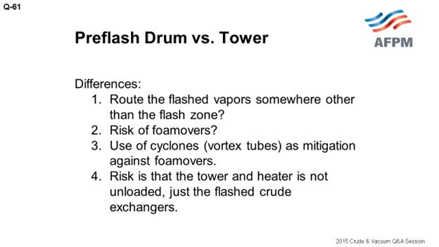
As Bruce said, if you just have a flash drum, you really need to be bold to route the flashed vapor somewhere other than the atmospheric tower flash zone. Routing the vapor directly to the atmospheric tower flash zone will debottleneck your flashed crude preheat exchangers; however, the flashed vapor has a tail (heavy end distillation) due to the single-stage nature of this drum.
With respect to the risk of foamovers, they happen. A properly sized drum will help mitigate them, as will the use of some sort of cyclones or vortex internals. Equally important is that whatever you have must be instrumented well, so you will know what to watch to maintain an upper hand and manage any foaming problem when it happens. You need to have instrumentation to watch your pressure, levels, and flow rate in the flashed crude. You will see, depending on the instrumentation in your unit, the indications come up (hopefully) before the foaming hits the main fractionator.
NAGASHYAM APPALLA (Reliance Industries Ltd.)
What is the Best Practice for monitoring the foaming incidence in the flash drum?
ALLRED (Suncor Energy, Inc.)
It is important to monitor the color on your products on the side drawer of the preflash tower because that is where you will see it first.
PRICE (Fluor Corporation)
We encourage people to watch for instability in their flashed crude flow rate, in the level, and in the pressure, as well as watching your pump for cavitation. We feel like that is where you will see it first.
CELSO PAJARO (Sulzer Chemtech USA, Inc.)
Just to clarify, if the preflash has a level glass gauge, you should see the foam there. The second point is that we have designed vortex tubes for preflash columns and preflash drums, and they work well. On our website, we have a video showing how it works. You can see how the foam is reduced between having nothing and just adding the foam-breaking element.
HAROLD EGGERT (Athlon Solutions)
You can also install a TI (temperature indicator) on the vapor out of that flash drum and watch the temperature. The temperature will change as you see increased foaming. The second part of this question is a commercial for this afternoon’s Principles & Practices session. There will be a session discussing Best Practices for caustic injection, and there are some interesting phenomena around the foaming in a flash drum, depending on where you put in the caustic for chloride suppression. So I encourage everyone to come to the P&P session this afternoon.
ANDREW SLOLEY (CH2M Hill)
If you are going to have a nuclear-level device in one place in a refinery, it would be on the preflash drum or tower bottoms. Some type of radiation instrument for online density and level measurement will greatly improve performance. There are other ways to monitor the foam level. But in these situations, by the time you notice it using other methods, the foaming event has already occurred. This is one place to spend money to make sure that if a foaming event happens, you will be able to react to it in real-time to prevent foam from entering the crude column.
LUIS GORDO (Amec Foster Wheeler)
Increasing diluted bitumen, synthetic crudes, and tight oil crude components in the feed increases the amount of light material that must be processed through the refinery (higher API feed). Depending on how the crude diet changes, the increase in light materials can be significant. This is often one of the limits to leveraging the typically discounted pricing of domestic tight oil.
Many refiners find that their ability to blend light tight oils into their feedstocks is restricted by the higher content of light materials [LPG (liquefied petroleum gas) and naphtha] in the crude. Preflash towers offer the advantage of debottlenecking crude preheat trains and atmospheric tower overhead sections in order to enable higher volumes of crude to be processed. Typically, preflash towers should be located after the desalter in order to mitigate corrosion/fouling. This spot is also convenient as a crude booster pump is almost always required at this location. Foaming is a concern for the design and operation of preflash towers/drums. Superficial liquid velocity must be kept below a certain threshold. Specific internals, such as vortex clusters that separate liquid and vapor by means of centrifugal force, can be considered. If the preflash tower is equipped with distillation trays/top reflux, there is a reduction in crude preheat temperature that must be offset by the crude heater.
In addition, if there is a plan to process heavy crudes also, then preflash towers need to be evaluated for the same due to lower light end loads. If this flexibility is required, then a preflash drum may be a better choice.
Economics that come into play are:
-
Increased Profit through incremental unit throughput,
-
Operating Expense of preflash tower condenser and pumps versus furnace firing cost, and
-
Capital Expense including modification of hot preheat train, crude tower overhead, and possibly furnace tubes versus new preflash tower, condenser, overhead drum, and pumps.
ANDREW SLOLEY (CH2M HILL)
Preflash drums and towers are a relatively complex subject. For revamping an existing unit, the addition of either may help the plant by relieving specific equipment constraints. The successful addition of a preflash unit requires a detailed knowledge of the existing equipment limits which requires a detailed analysis of unit performance based on validated plant data from test runs. No neat guidelines exist for general rules when adding a preflash when specific and complex constraints are involved.
For new units, specific situations merit preflashes. Having a preflash will generally allow for more flexibility to move toward both very light (45+ API° gravity) and very heavy (20- API° gravity). Specific examples where preflashes help unit flexibility are:
-
Very light crudes, limits on heater outlet vaporization: Recovery of very light crudes can be limited by heater outlet vaporization. Excessive vaporization can increase heater coking rates due to low liquid irrigation of the heater outlet tubes. A preflash removes some of the vapor, increasing liquid fraction at the atmospheric heater outlet.
-
Crude blends, asphaltene precipitation: A preflash can selectively remove C5- material from the crude. This may reduce asphaltene precipitation when processing a blend of light crude-heavy crude.
-
Aggressive heat integration, high heater inlet temperatures: A preflash may allow for lower inlet pressures to the fired heater when heat integration is very aggressive. This would be likely when running light crudes over a 525°F inlet temperature or heavy crudes over a 565°F inlet temperature. With current gas pricing in North America, highly aggressive preheat train outlet temperatures are typically not economical. However, the economic basis is different for many European or Asian refiners. Heat integration with extremely light crudes may benefit from a preflash at temperatures below 525°F.
-
Heavy crudes, desalter water removal: With heavy crudes, the desalter may leave a significant amount of water in the crude. A preflash may act as a dehydrator (water vaporizer) upstream of the hot train.
In general, preflash drums have a minimal impact on unit corrosion. They may marginally reduce salt hydrolysis by drying the oil. However, the change is small.
Preflash towers that have separate overhead systems from the crude distillation tower significantly increase atmospheric tower overhead corrosion problems. The preflash tower removes light ends from the atmospheric tower feed. This greatly increases water partial pressure in the atmospheric tower overhead, making aqueous chloride corrosion more severe. The increased corrosion normally holds true even if the removal of light material changes the atmospheric tower pressure profile.
For existing units, adding a preflash drum or preflash tower nearly always makes the unit less energy-efficient. Exceptions include when the unit has a very low atmospheric heater inlet pressure that limits heat integration or if vaporization in the preheat train is already creating large pressure drops.
For new units, the situation is ambiguous. On a constant return basis, adding a preflash tower may either increase or decrease energy efficiency. The result depends upon targeted crude preheat temperature, crude vaporization, crude gravity, preflash type, cost of firing versus cost of steam, product temperature to downstream units, and other factors.
BRUCE ALLRED (Suncor Energy U.S.A.)
At the Suncor Commerce City refinery in Colorado, we have three crude units with three separate preflash configurations. One crude unit has a typical preflash drum with overhead vapor going to the atmospheric tower flash-zone; one unit has a preflash column with an independent overhead condenser and reflux system and a side-cut draw; and, the other crude unit has a unique, convoluted quasi-preflash tower with a single overhead condenser and reflux system which also handles vapor from that atmospheric column that vents back to the middle of the preflash column. Each of these systems has their unique characteristics and limitations.
Preflash drums are useful for removing vapor from the feed to the atmospheric tower furnace. This is done to reduce unnecessary heat absorption into material that is already vaporized and to eliminate difficulties that can be encountered in control valves which would see two-phase flow, particularly in a multi-pass furnace. The use of a flash drum reduces process piping and furnace size due to the lessening of two-phase flow hydraulics. In theory, the optimal location to send the vapor is to the spot on the atmospheric column that most closely matches the vapor steam. However, the reality is that most refineries with preflash drums send the vapor to the flash zone. This is done since preflash drums can be prone to have foaming and carryover of heavier liquid, which puts reduced crude in locations not designed for reduced crude. This leads not only to dark light oil products, but it can also put sulfur or naphthenic acid into places that were not designed for it. The downside to sending the vapor to the flash zone is that the vapor will quench the temperature in the flash zone, so the furnace outlet temperature must be set to compensate. Since the drum, overhead line, and furnace sizes are already fixed in a refinery, there is limited flexibility for opportunity crudes unless the sizing of these components allows for the changes in flow hydraulics, heat transfer, etc.
A preflash column can be a better option if it has its own reflux and vapor recovery. It allows for a side draw of light products and, if adequately sized, may provide flexibility for variable API feeds depending on loading and turndown. The downside to a preflash column is the money required to build, maintain, and operate a separate overhead reflux system. And also, just like a preflash drum, you need to watch out for foaming in the tower and low velocities in furnace tubes, which may cause premature coking of the furnace tubes. If much lighter crude is run, the preflash tower may be too small and still be susceptible to foaming and liquid carryover. For more detailed discussions on foaming in preflash drums and columns, see Question 61 in the 2012 AFPM Q&A Answer Book.
Another option that was highlighted in a recent publication11 has a hybrid option that uses liquid from the atmospheric tower reflux to the preflash column. This article claims that energy efficiency of this arrangement is superior to both the preflash drum and preflash tower arrangements. I have no experience with this hybrid option, but the claim seems plausible.
We have not seen severe problems with foaming any of our three crude units; but if a crude slate that is dramatically different from the normal slate that is fed to one of the units, we have to monitor closely for any signs of flooding or accelerated fouling.
The bottom line is that preflash drums and columns can add flexibility in running opportunity crudes but only to within the limits to which these components are designed.
Having a preflash drum or column increases energy efficiency with removal of the lighter components in the crude to reduce operating pressure/pressure drop requirement in the preheat exchanger train and to reduce furnace duty requirement. However, the reduction of the lighter components with the preflash system will also decreases the amount of flashed vapor in the atmospheric flash zone, which will need to be compensated by increasing the crude heater coil outlet temperature and/or crude tower bottom stripping steam flow. With light crudes, typically a 10 to 20% debottleneck can be achieved in the atmospheric tower, heater, and condenser.
With a preflash drum (as opposed to a preflash tower), the overhead is usually routed into the flash zone for fear of foamovers contaminating products, and the resulting upsets in downstream units. Cyclone separators (also known as vortex tubes/clusters) in the preflash drum are effective against foamovers, but one foamover that gets away from the cyclones causes so much mess, product loss, catalyst poisoning, and economic loss that most refiners shy away and route the overhead of flash drums into the flash zone. When this happens, there is zero unloading of the heater and the tower.
The preflash tower (as distinct from the drum) enables the refiner to recover naphtha (and sometimes jet fuel) that completely bypass the main atmospheric tower. A well-designed preflash tower has a pressure drop measurement and other warning instrumentation that can see a foamover before it gets into the product. The preflash tower also provides a venue for discharging the desalter relief valve without causing tray damage. However, the drawback of a preflash tower is a reduced diesel yield in the atmospheric tower because the light ends help with the stripping of the crude. This effect is usually small but needs consideration. Additionally, with some of the naphtha removed upstream, it can drive the atmospheric tower into a water dew point limitation. This may constrain the amount of stripping steam that can be used and therefore the diesel recovery. (Note that the effect of the higher naphtha boiling point is higher, and reduction in off gases may counter the water dew point issue. You have to study it to be sure.)
Another advantage of using a preflash drum (or a preflash tower) is the removal of light paraffins (C5 minus) which can reduce downstream asphaltene precipitation and fouling.
Year
2015
Process
Question 62: When increasing the vacuum tower cutpoint, what measures have you employed to mitigate the impact of chlorides in the overhead diesel or light vacuum gas oil sections of the vacuum tower?
WEBER [Marathon Petroleum Corporation (MPC)]
Just take all of the salt out from within your desalters, and you will not have chloride problems. [Laughter] That is probably the simplest and least helpful answer. But obviously, the better job you do desalting your crude, the fewer chloride problems you will have in both towers. Short of that, the chloride issues in the vacuum tower are going to be driven by the difference in transfer temperature on your crude tower and your vacuum tower. Magnesium chloride will hydrolyze very easily and occurs primarily in the crude tower.
Calcium chloride is likely the bigger culprit in vacuum towers. If there is a 100°F difference in crude and vacuum transfer temperatures, some hydrolysis in the vacuum tower will occur. If the desired vacuum tower cutpoint can be achieved in a different way other than maximizing vacuum heater temperature, such as lowering column pressure, hydrolysis and subsequent salt formation will be reduced. Most refiners are maximizing vacuum heater transfer temperatures; so again, managing the chlorides coming out of you desalters is the key. I will note that we have seen an increase in fouling in the LVGO (light vacuum gas oil) pumps and exchangers, which is a more recent phenomenon. One item to note is that although we have not done enough work to be conclusive, we have observed more bromine or bromides when those salts were analyzed.
BRADEN (NALCO Champion)
Yes, I have to agree with John. Optimizing the desalter using mechanical, chemical, and operational analysis is critical for removing as much of the chlorides as you can and dehydrating the crude. You have a variety of options such as mixed valve studies, crude and water level controls, mud wash analysis, and washwater analysis including the pH. The refinery can also look at the overhead water and measure it for pH, chlorides, iron, organic acids, amines, cationic metals, and ionic species. Every piece of information you can gather about optimizing chloride removal is key. Then of course, the refinery should have the right neutralizer program for the chlorides in the overhead to protect from corrosion. Lastly, have a continuous monitoring program – either Pathfinder probes or some type of monitoring system of your choice – to see what is going on.
PRICE (Fluor Corporation)
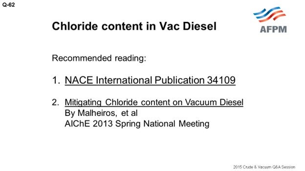
I recommend you read two articles. One is NACE (National Association for Corrosion Engineers) Publication 34109, and the other is another paper from the 2013 AIChE meeting that was published by Petrobras. This paper is interesting as they have noted that although this problem has not been solved, Petrobras has seen some results with an increased fractionation reflux rate in the vacuum pumparounds to help mitigate the chloride content in the vacuum diesel. The increased reflux in the vacuum pumparounds also helps the endpoint of the distillation.
BILLS CATES (Hunt Refining Company)
Is this problem more prevalent in vacuum towers that are run wet using stripping steam versus running at a dry tower without stripping steam?
WEBER [Marathon Petroleum Corporation (MPC)]
I will say that we have seen it in a variety of towers, whether they are deep-cut or not. I think most of our towers do have stripping steam, so I cannot comment on the dry tower.
WATTS (LyondellBasell Industries)
We have not seen this issue at our refinery. A part of it, of course, starts with analyzing the crudes to know what you have and, as the other panelists said, managing your desalters and your overhead systems.
PRICE (Fluor Corporation)
The ones we know of all used stripping steam.
NAGASHYAM APPALLA (Reliance Industries Ltd.)
Sodium chloride is normally considered a stable salt. Is there a theory that, in presence of naphthenic acid, hydrolysis of sodium chloride does take place in the transfer line and leads to more chloride in vacuum tower overhead?
WEBER [Marathon Petroleum Corporation (MPC)]
I am not familiar with that theory, but it sounds possible.
PRICE (Fluor Corporation)
The following two articles may have information that will be of interest to you:
-
Gray, M. R., Eaton, P. E. and Le, T, “Inhibition and Promotion of Hydrolysis of Chloride Salts in Model Crude Oil and Heavy Oil” (Petroleum Science and Technology, 26:16, 1934-1944), 2008.
-
Gray, M. R., Eaton, P. E. and Le, T, “Kinetics of Hydrolysis of Chloride Salts in Model Crude Oil” (Petroleum Science and Technology, 26:16,1924-1933), 2008.
NAGASHYAM APPALLA (Reliance Industries Ltd.)
So, has anyone seen any correlation between the increased naphthenic acid versus the increased chloride in the vacuum tower?
RUSSELL (RUSTY) STRONG (Athlon Solutions)
Naphthenic acids will participate in accelerating hydrolysis. Literature primarily talks about it in the raw crude at the crude unit. You will likely see more chlorides in the crude unit tower and overhead, but that may also apply in the vacuum column. To respond to Mr. Appalla’s question, there is an understanding that sodium chloride is much more thermally stable than the calcium and magnesium chloride. What is not clearly understood amongst many in the industry is that magnesium chloride, when it decomposes, does not decompose from magnesium chloride (MgCl2) directly to magnesium hydroxide and hydrochloric acid. There is not a complete hydrolysis. Instead, you find an intermediate step where the magnesium becomes a hydroxylchloride. One of the chlorides is lost first, and the resultant magnesium hydroxylchloride (MgOHCl) is actually fairly thermally stable compared to the first chloride becoming HCl.
The magnesium hydroxychloride will then enter the vacuum column where it is often subjected to more severe thermal stress, still less thermally stable than sodium chloride, and will come apart. The organic/naphthenic acids will play a role in accelerating the thermal decomposition, and more HCl may be observed in both towers as a consequence.
The stripping steam: If you have velocity steam or stripping steam in a vacuum column, you most likely have a pretreated steam that has a neutralizer in it. The partial pressure of the steam in that vacuum column near the top is relatively high compared to what you see in a crude unit. As a consequence, the neutralizers involved in the stripping steam are also at higher partial pressure and can actually salt out with the chloride that is present, causing tower and top-cut corrosion and fouling.
Two of the steps that can be taken are: 1) for the vacuum column, find a way to satellite-feed your neutralizer so that the steam that gets in the vacuum column is not carrying neutralizer from the steam with it. Then, treat for pH in the overhead near the ejectors, rather than enabling steam in the tower to cause salting in the vacuum column. You will have to live with the ammonia that comes from the nitrogen-bearing crude, but you can get rid of much, if not all, of the problem by addressing the neutralizers.
JEFFREY ZURLO (GE Water & Process Technologies)
Just to add to what Rusty said, in addition to the items he talked about for changing the steam location, you can also look at what neutralizing amines you are putting into your steam system. The different amines used in the steam that can get into the crude and vacuum towers have different salt points. So that is another way to potentially control the salt fouling and corrosion in the vacuum tower.
DENNIS HAYNES (NALCO Champion)
The Best Practice is to optimize the desalter performance to achieve the best chlorides removal possible. This may include additional efforts around slop handling and better brine removal in the tank farm prior to the crude unit desalters; also, caustic use is a well-known, effective method to reduce distillation column overhead chlorides.
GLENN SCATTERGOOD (NALCO Champion)
To control vacuum tower overhead chloride concentration, the caustic injection into the desalted crude downstream of the desalter should be optimized. A quick study of caustic injection rate versus vacuum overhead chloride will provide the data necessary to determine the best caustic injection rate and help set a reasonable chloride target for the overhead. Once caustic is optimized, and during the caustic optimization step, the pH of the first dipleg condensing system should be monitored as the chloride will concentrate in the first condenser. Proper neutralization is necessary to control the corrosion in this area. Corrosion rate monitoring of the first condensing dipleg is important.
VILAS LONAKADI (Amec Foster Wheeler)
Like any other fractionator, increase the vacuum tower overhead temperature. However, this would increase the vapor load to ejector. Vacuum towers that are equipped with precondensers may be able to handle this additional load. Depending on the chlorides content and the increase in temperature, options such as operating spare ejectors, revamping ejector system, and/or adding a pre-condenser can be considered.
JOHN WEBER [Marathon Petroleum Corporation (MPC)]
Chloride salts that are not removed during the desalting process will be hydrolyzed to HCl in either the crude or vacuum tower heaters. The HCl will wind up in the tower overheads and can cause problems with corrosion or react with amines in the tower to form salts, which foul process equipment.
Obviously, minimizing salt content in the desalted crude will mitigate chloride issues in both towers and should be the primary focus for improvements. In the vacuum tower, the amount of salts hydrolyzed correlates to the difference between the crude heater temperature and the vacuum heater temperature and will be more pronounced in deep-cut vacuum towers. Mitigation of chlorides in overhead systems will be similar to control measures in the atmospheric tower.
MPC has observed salting in the LVGO circuits at several of our refineries, and it appears to be a recent phenomenon. Bromine has been observed in these salts and may be contributing to a change in salting potential in these circuits. These units run a wide variety of cutpoints and is not isolated to only the deep-cut units.
MICHAEL BRADEN (NALCO Champion)
First is to optimize the desalter via chemical program, mix valve study, crude and water level controls, mud-wash analysis, mechanical review, and a washwater analysis including pH. Second is to analyze the overhead water for pH, chlorides, and iron along with organic acids, amines, cationic metals via inductively coupled plasma (ICP) and also analyze anionic species by ion chromatography (IC). Third is to employ a neutralizer program to control the chlorides and inhibit corrosion. Fourth is to have continuous monitoring via Pathfinder®, probes, or Permasense®.
MAUREEN PRICE (FLUOR)
The hydrolysis of inorganic salts produces hydrogen chloride which will distribute between the vacuum column overhead and upper side draw(s). Improved upstream desalting and/or caustic injection can be considered to reduce the quantity of hydrolyzable salts present. See NACE International Publication 34109 for additional information. One Southern California refiner saw his chloride problem disappear after he added second-stage crude desalting.
Fluor also recommends the following paper as an excellent reference on the subject: “Mitigating Chloride Content on Vacuum Diesel” by Malheiros, et al.12 The paper notes that there is still much to learn about the subject but that a higher fractionation reflux rate has the benefit of mitigating the chloride content in the vacuum diesel, in addition to expected sulfur and end point distillation reductions.
Year
2015
Process
Question 63: What type of facilities have you used to cool hot vacuum residue going to storage to avoid plugging problems and facilitate reprocessing?
WATTS (LyondellBasell Industries)
I am going to focus on the system we have and also some of the issues we have experienced. The majority of our resid that is produced off the crude unit vacuum towers is sent through the hot resid system straight to the cokers. We have two crude unit trains. We process 120,000 to 140,000 barrels per day of crude on each unit. We have two cokers. Each coker has four drums. One coker can process up to 40,000 barrels per day of resid on a four-drum operation. The other can process 60,000 barrels per day of resid on a four-drum operation.
Our cold resid system is where we send excess resid, but we also maintain that system during normal operation. So, what we do is take uncut resid at about 400°F+ and add cutter. A base cutter for us is heavy cycle oil from the FCC. That is typically the only place we send it. Then we make up, as needed, with distillate-range material. The majority of the time it is LCO from the FCC. Basically, we target a maximum tank temperature. We have a temperature limit of 210°F, so we try to keep it around 200°F. When we are stacking a lot of resid, we can hit a viscosity spec. We have found that we need to add about 30 to 40% cutter to hit that spec.

We have three main modes of operation. The first is typically the mode in which we operate. I call it ‘resid system balanced’. Basically, this is where the coker is pacing the cold resid. So typically, we are sending 6,000 to 10,000 barrels per day to tank and pulling that equivalent amount back to the cokers.
We have what I call ‘resid stacking mode’. With the current system, we can stack up to 30,000 barrels per day of resid with a minimum of 30% cutter. That leaves about 21,000 barrels per day of resid you can stack.
The last mode, which we do not do very frequently, I call ‘resid pull’. Typically, this occurs after a short outage of the cokers. After the outage, we will pull back resid that was stacked. Occasionally, the economics support going out and purchasing resid, but the way our refinery operates is that we are typically close to limits on the cokers when both crude units are at full rates because the resid yield is typically above 30%.
The last piece I want to talk about is basically how we minimize the potential for resid line plugging; basically, it is managing the temperature. As I said, we have limits on what we can send to the tank, but we operate in a relatively tight window. We try to keep the temperature above 190°F. Basically, we have added in the orders for the console operators that one time per shift, they need to heat up the cold systems. So, they do that about twice per day. Resid, as I am sure a lot of you are aware, is hard to meter. So basically, what we have done, based on operating experience, is set minimum valve output limits where we are all alarmed if the resid rate gets too low. That is based on historical information. So, for us, the biggest challenge for managing the hot and cold resid system is during major upsets when we lose production of our main cutter source and significant coking capacity. This is typically where one or more of the cokers go to a two-drum operation. That is where we are most likely to have issues with plugging in the sections of the hot or cold systems.

In fact, back in 2010, we had a refinery-wide emergency shutdown. We actually plugged up the hot system between one of the crude units and the cokers. It took a lot of money and time to unplug that system. Last year, we also plugged up a small part of the cold system. The highest risk for us is when we have a major refinery outage because multiple assets or operating teams have to communicate with each other to make sure we get cutter in the lines.
PRICE (Fluor Corporation)
I want to second what Ed said: The challenge of storing hot resid is very difficult, although folks who make asphalt and store it have more chances to do this than others.

To overcome the difficulty in storing hot resid, many refiners in Southern California will use box coolers, diversion air coolers, or a tempered water bath. Normal cooling water cannot be used because it will cause extreme fouling on the water side, as well as plugging on the hydrocarbon side. The diversion air coolers incorporate special design features to ensure that the approach to pour point is adequate to prevent plugging on the hydrocarbon side. On an emergency basis, quenching with cold gas oil product is about the best option you have.

EBERHARD LUCKE (CH2M Hill)
I do not know if you mentioned this; but if you did, I apologize for making you repeat it. When you process cold vacuum residue in the coker unit, because of heat integration and the amount of cutter stock you need, do you have a limit, such as a percentage of total fresh feed, up to which you can process?
WATTS (LyondellBasell Industries)
A typical operation is where I would, say, pull less than 10,000 barrels per day out of 90,000 barrels. I know that we pulled quite a bit more than that in the past – up to 20,000 barrels, or somewhere in that range – out of 90,000; so, a little over 20%.
JAMES DOHERTY (LyondellBasell Industries)
To add to the point and answer the question, I work on the cokers with Ed. We would hit that limit. Sometimes, right before we got to that limit, we would see increased foaming on the cokers. That would limit our pullback instead of a heat limit.
WATTS (LyondellBasell)
I want to comment on what Maureen mentioned. I did not really add detail to how we cool off our resid. We add cutter. We have cooling water exchanges on the crude units. But a couple of years ago, we installed a temporary cooling system just before we sent the resid to the tank. We actually cool off the resid with glycol. That is a much better system, in terms of reducing exchanger fouling. It allowed us to reduce our cutter significantly and also to stack more resid. With that system, we were able to stack as much as 40,000 barrels per day of resid. Without that system in place, we were limited to somewhere around 20,000 barrels per day.
VILAS LONAKADI (Amec Foster Wheeler)
In most cases, vacuum residue is cooled with the incoming feed to a crude unit or other streams that require heating. Other facilities employed are the use of steam generator or tempered water system. Viscosity, and pour point of vacuum residue, along with the design temperature of the storage tanks, tracing of the product rundown line, type of heating facilities for storage tanks, and storage duration should all be taken into consideration when deciding the storage temperature and design of the associated facilities.
EDWIN WATTS (LyondellBasell Houston Refining)
There are several different system designs that are used to manage excess resid produced off the crude units. Our excess resid is mixed with a cutter stock and cooled to about 200°F using cooling water exchangers prior to going to storage tanks. The cutter is a combination of FCCU heavy cycle oil and distillate range material. The resid is either sold or pulled back to the cokers as feed. It is important to maintain adequate flow, temperature, and cutter to prevent the system from plugging up.
MAUREEN PRICE (FLUOR)
Ideally, hot vacuum residue is cooled through the preheat train to about 400°F before being sent to a storage tank that is designed for this hot temperature and in accordance with the codes and standards which can present a challenge. To overcome the design challenges of storage at (or near 400°F), a box cooler, diversion air coolers, or a tempered water bath can be used. The use of normal cooling water is not recommended (due to the risk of extreme fouling on the water side AND plugging on the hydrocarbon side). Diversion air coolers incorporate special design features to ensure that the approach to pour point is adequate to prevent plugging on the hydrocarbon side. For emergency rundown, the hot vacuum residue can be quenched with cold gas oil product to be sent to a storage tank for reprocessing.
Year
2015
Process
Question 64: What are acceptable makeup water streams that can be used for coke cutting which will not affect the coke quality?
MAYO (CITGO Petroleum Corporation)
With regard to coke quality, a lot of the available streams are acceptable. A few of the additional considerations to take into account are: Is this makeup water stream going to add overall load to my wastewater treatment facility? Is this new water? Is this water that I can recycle? Streams that are acceptable are: stripped sour water. If you are not reusing this water at your desalters or FCC wet gas scrubbers, then it would be an acceptable stream.
Refinery effluent water: If you have treated water that is nice and clean, consider hydraulics which allow you to bring it back to the front, if that is feasible. Waste heat boiler blowdowns and cooling tower blowdowns are the streams that are wasted from other processes and typically just sent to the wastewater treatment facility. So, after you look at your recycles, you can obviously go with well water or river water systems, if your water quality allows.
From a quality standpoint, refiners should be monitoring the TSS (total suspended solids) on their cutting water. This comment is just a reminder to people to make sure they consider the TSS of their makeup stream to ensure it does not cause the TSS of the overall stream to increase above the manufacture's recommendation. Make sure that the stream you bring in will not cycle up that cutting water system. Most of the cutting tool manufacturers suggest staying under 2,000 ppm TSS to minimize the erosion on your cutting nozzles. So that is a consideration to take into account. And then naturally, any of the bad contaminants in your water stream should be evaluated and reviewed with your Environmental group: You do not want to bring in any makeup streams with hydrocarbons or any other contaminants that will give you air quality issues.
EBERHARD LUCKE (CH2M)
The answer to this question depends on the type of coke that is produced in the unit. Anode grade coke and needle coke production have much higher requirements regarding coke quality than fuel grade coke production.
For fuel grade coke production, I have seen many units using stripped sour water as makeup water for the cutting system. In some cases, there were more concerns regarding the impact on the hydraulic cutting system itself (corrosion) than on the coke quality. The quality of the sour water also depends on the type of crude oil that is being processed in the refinery. In some cases, stripped sour water was rejected as cutting water makeup due to the high level of contaminants that were not stripped out of the water.
For anode-grade coke production, stripped sour water may still be suitable as makeup water, depending on the type and quantity of contaminants that can be expected.
VILAS LONAKADI (Amec Foster Wheeler)
The selection of makeup water streams for coke cutting is made based on the quality of the streams. Traditionally, non-phenolic stripped sour water or utility/raw water has been used as makeup water. In terms of quality, the H2S Content, pH, chloride levels, total solids content, CaCo3, in terms of hardness and alkalinity, need to be monitored for the makeup water and decoking water to the required levels. These qualities of the makeup water affect more – in terms of the material selection for the downstream equipment such as coke cutting pumps, quench water pumps, pipelines, odor, and environment – rather than the quality of coke itself.
BRENT MAYO (CITGO Petroleum Corporation)
With regard to effects on coke quality, most available makeup water sources are acceptable. The makeup water stream should be evaluated to determine if the source would create “additional” water that would increase hydraulic load on the wastewater effluent treatment facility. Next, prioritize the available streams based on your facilities’ quality, starting with the cleanest options. Examples are:
-
Stripped sour water [if not already in use at desalters or FCC WGS (wet gas scrubber)]
-
Refinery effluent,
-
Waste heat boiler blowdown,
-
Cooling tower blowdown, and
-
Well/river water.
When evaluating available water sources, quality concerns can include:
-
Low Solids: Ensure that the makeup source keeps the overall cutting water TSS below 2000 ppm (typically recommended by the cutting tool manufacturer to minimize erosion of cutting nozzle).
-
The Absence of Hydrocarbons: Potential oily water sources should not be used to avoid emissions and downstream emulsions that may be difficult to separate. Prior to making any changes, verify your coke product specifications to ensure that changes in coke quality will not affect your ability to sell the coke.
Year
2015
Process
Question 65: Discuss operating conditions and economic drivers to produce maximum diesel from the coker.
MAYO (CITGO Petroleum Corporation)
When your margins indicate the need to pull more diesel, you have two options: You can check the top of your tower, or you can adjust overhead temperatures and fractionations to confirm that you are pushing the maximum amount of heavy naphtha down into the diesel. The pitfall to avoid is cooling it off too much and worrying about salting on the top of the tower. You can get aggressive but be careful with regard to salting.
And then on the bottom end, a lot of us have fallen into the pitfall of trying to extend heater decokes, such as overuse of your heavy coker gas oil pumparound trying to recover as much of that preheat in order to raise coil inlet temperatures. Sometimes you do not let enough diesel traffic up the tower. So, the two modes you really need to watch are overcooling and overuse of that lower pumparound.
WATTS (LyondellBasell Industries)
I see a lot of similarities with what we do at the refinery. We obviously take a holistic approach to optimizing diesel on our refinery with the goal of pushing to a frontend distillation limit or flash limit; and on the backend, to push the 90% point or final boiling point limit. So, the streams we put in front of the diesel treaters are coming off of the crude units and the cokers. Then, we pulled a diesel stream off of one of our cat feed hydrotreaters. We found that the worst quality streams, in terms of ability to treat, on our diesel treaters are the light vacuum gas oil off of our heavy sour crude unit: the 636 diesel off the cat feed hydrotreater that is been hydrotreated. And then, the third would be the coker streams.
In terms of undercutting on the front end, typically the downgrade between coker-like gas oil and coker naphtha is a lot greater than what you see on the crude units. So, we are going to drive to either a temperature limit or a frontend distillation limit.
WILLIAM (BILL) HURT (Keystone Engineering Inc.)
What is your lowest operating pressure that had been maintained in your fractionator overhead?
MAYO (CITGO Petroleum Corporation)
For the coker fractionator in decoke mode, when we are running a side down for one of our smaller cokers, we can run down into the 10 psig (pounds per square inch gauge) range. But with normal operating conditions, the mid-20s is typically the average operating pressure.
MEL LARSON (KBC Advanced Technologies, Inc.)
There are some coker fractionators that do not have an intermediate pumparound, as there is on the light distillate section. Has anyone considered adding that so you could get the lift and not have to use as much at the bottom of the pumparound? Secondly, has anyone looked at coker naphtha fractionation on the backend to avoid the problem of salt deposition at the top of the tower while still optimizing the cutpoint? There are places around the world where we have seen both. Has anyone considered that as a revamp option to maximize flexibility and operation here in the States?
MAYO (CITGO Petroleum Corporation)
To respond to your first comment, that opportunity absolutely exists at our facility right now. One of our cokers has the pumparounds in the heavy gas oil and light gas oil circuits and just a draw for the blended oil (kerosene). For the other coker, we just have a draw on the light coker gas oil. And absolutely, if we are having any flooding issues at the top, any heat we allow up into that section will compound the issue. So an additional pumparound would absolutely help us in that situation.
WATTS (LyondellBasell Industries)
We looked at different projects on the pumparound. I am not that familiar with them, but I know we are – as are most refineries – looking at ways to shove more diesel into treaters. I would say that we do face issues when we shift to a two-drum operation on the cokers with basically being at minimum pumparounds and removing too much heat.
GARY HAWKINS (Emerson Process Management)
Consider the coker as two sections: the coke drums and heaters section and the fractionation and vapor recovery section. For the coke drums and heaters section, maximum throughput is achieved by optimizing the coke drum cycle; basically, taking advantage of as much of the drum capacity as possible without risking foaming in the transfer piping to the fractionator. Benefits can also be achieved by maximizing the efficiency of the fire heater operation. But the coker fractionator is unique amongst the fractionators in refineries (crude, vacuum, FCC and hydrocracker being the others) in that the feed to the column takes an upset in vapor flow every time the drums switch. This is an excellent application for multivariable predictive control targeted specifically for optimal fractionator control through the “bumps” of coke drum switching.
SRINI SRIVATSAN (Amec Foster Wheeler)
Usually maximizing C5+ liquid yields also maximize revenue to a refiner. However, if the HCGO is not going to be a downstream conversion unit, it is possible to have a large differential in the pricing between LCGO (light coker gas oil) and HCGO (heavy coker gas oil), with LCGO being priced at a premium. The economic driver to produce maximum diesel from the coker then depends on differential pricing between LCGO and HCGO.
Typically, delayed coking units (DCU) designed for maximizing C5 + liquid yields are designed for low pressure and ultra-low recycling. Amec Foster Wheeler has several units operating at coke drum pressures of 1.05 kg/cm2 (kilograms per square centimeter), which is the equivalent of 15 psig (pounds per square inch gauge), and a throughput ratio of 1.05 that make an HCGO product suitable for further processing in downstream hydrocracker units. While units can be designed for zero recycle (1.0 TPR) to further maximize C5+ liquid yields, it is to be noted that this increased liquid yields is mainly from the production of an extra heavy coker gas oil (XHCGO) stream or combined HCGO, if XHCGO is not drawn as a separate product. One has to carefully evaluate the quality of XHCGO or the combined HCGO product produced and the ability of the downstream processing unit to handle the product in this case. The contaminant levels – such as (nickel + vanadium), Conradson carbon, and C7 insolubles – in the combined HCGO stream, in a true "zero" recycle operation, can be 2.5 to 4 times higher than one operated at 5% recycle.
If producing diesel (LCGO) is the only objective, higher operating pressures favor the production of diesel material (LCGO). Based on the pricing differential between LCGO and HCGO, an optimum pressure can be selected that maximizes refinery margins.
BRENT MAYO (CITGO Petroleum Corporation)
When margins encourage diesel yield over naphtha, operating conditions that help improve diesel recovery are:
-
Adjusting pumparounds above the diesel section of the tower to improve fractionation (reductions in tower overhead temperature can result in salt deposition at too low of temperatures) and
-
Avoiding over-use (as a preheat benefit) of lower pumparounds to allow increased vapor traffic higher up the column [ensure piping and equipment can handle increased draw temperatures MAWT (maximum allowable working temperature) and thermal expansion]. Also, ensure that changes to the diesel final boiling point are within allowable range for downstream units.
Year
2015
Process