Question 46: What is the panel's experience with in-line blending and in-line certification? What are the main differences between in-line blending and certification?
Greg Harbison (Marathon Petroleum)
For clarity, a common definition of “in-line blending” is required. Marathon defines in-line blending as a system that pumps multiple blend components from individual tanks, which are typically “live” (either receiving or capable of receiving components from a process unit or pipeline delivery) into a header. The header generally contains static mixing to ensure homogeneity of the blend. The header is lined up to a finished product, or “certification” tank. Often, property analyzers are used to adjust the blend recipe as the blend is being made. Some of the more common analyzers used are octane (engine or NIR), RVP, sulfur, and distillation. Computer control schemes can be configured to adjust the blend recipes, based on the analyzer readings and target values for given properties. Manual adjustments to the blend recipes can also be made by gasoline blending operators, if computer control is not available. It is common to have routine check samples sent to the refinery control laboratory to both verify the on-line analyzer results and also compare the blend results to the expected values from the blend recipes. The final tank blend is subsequently certified by the refinery control lab. Marathon has in-line blenders at many of our refineries.
In contrast, blending can be completed in a batch-wise manner (sometimes referred to as “splash”-blending), by pumping pre-determined volumes of individual components into a tank, and then circulating the entire tank prior to certification testing. On occasion, Marathon utilizes a variation of this approach when “re-blending” a tank to correct an off-spec result.
In-line certification occurs when blending analyzer results are used rather than laboratory results to characterize the finished product. This process presumes adequate mixing in the blend header, a homogenous blend in the tank, and applies the aggregate results of the blend (typically through an integrative computer control scheme) to the entire batch. Without in-line blending, in-line certification is not possible, although in-line blending is possible without in-line certification. To certify a blend in-line using an analyzer, a rigorous statistical comparison of in-line versus laboratory results is required to prove a strong correlation between results. Federal regulations (40 CFR) contain a list of which properties may be certified in-line and define the requirements for demonstrating compliance with applicable specifications. Road octane (AKI) is generally regulated by individual states, not by the federal EPA, and doesn’t fall under the jurisdiction of 40 CFR. The states typically have adopted some version of ASTM D4814 for octane testing. To in-line certify octane via analyzers, pipeline carriers / customers must approve the alternate test method, generally with the same burden-of-proof (strong correlation between analyzer and laboratory results) for the refineries. With any in-line certification process, a program to routinely verify analyzer results is necessary. Marathon has developed corporate guidelines for the use of on-line analyzers in certification testing.
In-line certification can be used on individual properties alone, which then requires laboratory testing for the remaining properties, or it can be used for all properties of the blend, potentially allowing “live” exports from the blend header to a product pipeline. Several Marathon refineries in-line certify some properties of the finished blends. Marathon does not live blend to product pipelines.
In-line blending can have several advantages to batch-wise blending:
•As mentioned, if coupled with in-line certification for all properties, it provides the opportunity to blend directly to a pipeline, which in turn would reduce finished tankage requirements for the refinery. This can reduce a refinery’s working capital load, by not having to carry as many tank bottoms levels.
•There is much tighter precision / less specification give-away on the blend properties, as the computer control schemes quickly and easily adjust the blend recipes in real-time.
•On-line analyzers used for in-line blending can help detect changes in component make-up / properties, via shifts in the aggregate properties of the blend, allowing for larger-scale recipe adjustments to correct for the changes.
•Blending and certification times can be reduced, as the blends are generally on-spec the first time, and do not require re-blends. There are, of course, some inherent risks associated with in-line blending and certification:
•When shipping “live,” analyzer malfunctions / failures can result in releasing off-spec product.
•If not shipping “live,” minor analyzer malfunctions / shifts may result in unexpected re-blending requirements. For example, in a batch blending operation, it is possible that sufficient “cushion” was built into the blend recipes to allow for changes in the component make-up. However, with analyzers automatically adjusting blend recipes to drive closer to a spec limit (e.g., RVP), it is possible that a blend which was thought to have finished on-spec actually comes back off-spec. Then, re-testing and/or re-blending may be necessary, which may result in shipment delays and additional cost.
John Clower (Chevron)
At the Richmond Refinery, we blend gasoline in-line from multiple component tanks to a finished product tank. The tail line, finished gasoline, product has multiple analyzers that are monitored by operations continuously.
F1 and F2 are monitored by engine analyzers and are certified by the state for on-line tank release, allowing for zero “giveaway” on octane.
Five separate analyzers exist for RVP, aromatics (including benzene), olefins, sulfur, and distillation. These non-certification analyzers are confirmed by the lab twice per shift. The product tank final must include laboratory analysis of these five components.
Year
2010
Process
Question 47: What are the best practices for corrosion probe selection, installation and reliability, especially in high temperature and/or high H2S environments?
Alec Klinghoffer (Coffeyville Resources)
Some things to consider when selecting and installing corrosion probes are to match the metallurgy of the probe to the pipe. Also, it is very important to try and determine where the corrosion is actually occurring on the pipe when installing the corrosion probe. This is important because the probe is a “point” measurement and corrosion can take place in the vicinity of the probe without the probe actually measuring it. The probe depth should also be taken into consideration because one wants to measure on the edge/ID of the pipe and not somewhere in the middle of the pipe.
In high temperature, high H2S environments, it is important to match metallurgy and packing material. Typically, for normal applications, the packing is made out of Teflon. This cannot be used in high temperature applications so care must be taken to ensure a suitable packing material is used. In addition, metallurgy is a consideration in high temperature applications. It is best to use Hastelloy is high temperature, highly corrosive environments.
The probes need to be reliable as the data needs to be “long term”. Since corrosion is a slow process, data needs to be collected over a 5 – 6-month period to get an accurate representation of corrosion rates.
John Clower (Chevron)
Recommended techniques for corrosion monitoring include the use of electric resistance probes and AUT (automated ultrasonic testing).
ER probes can be ordered with some consideration for the process environment and are available in retrievable, retractable, fixed, and flanged mountings. They are rated up to 6000 psig and 850 °F.
AUT is transducer mounted externally, and thus suitable for any process environment. AUT corrosion mapping has many advantages over internal corrosion probes or external UT monitoring:
•High sensitivity corrosion detection
•Quantitative thickness measurements
•Faster results versus manual UT
•Repeatable
•No welding required
•Ease of interpretation
Sam Lordo (Nalco Company)
Corrosion probe selection is based on the velocity, metallurgy and the operating conditions of the system to be monitored. They are very effective when properly installed and maintained.
Year
2010
Process
Question 48: In your experience, what is the preferred online (non-destructive) method to identify risk of HIC (hydrogen induced cracking) in gasoline processing units?
Alec Klinghoffer (Coffeyville Resources)
The preferred method of identifying the risk of hydrogen induced cracking is to measure the permeation or flux of hydrogen on the outside surface of the equipment and correlate this to the corrosion rate on the inside of the pipe. There are several manufacturers of this type of equipment where a probe is attached with straps or a magnet and the flux of H2 is measured at the pipe surface. The small, portable equipment is equipped with a highly sensitive H2 analyzer. The sensor registers the concentration of H2 in the air stream. Since H2 is highly diffusible in air, the background level of H2 is usually low and stable and therefore the increase in H2 in the air stream is a dependable way of measuring hydrogen at the surface. The apparatus uses correlations to determine the corrosion rate on the inside of the pipe or vessel. The advantages of these analyzers are that they are portable and dependable, the work for temperatures up to 1100F, are intrinsically safe, collect data in “real time” and are reliable. Fixed monitors are also available. Typically, these types of analyzers collect data in a small amount of time and can calculate corrosion measurements in minutes.
Greg Harbison (Marathon Petroleum)
If the expected damage mechanism could result in hydrogen blistering, hydrogen induced cracking (HIC), or stress-oriented hydrogen induced cracking (SOHIC) our experience has shown that automated ultrasonic (AUT) scan is the most beneficial in identifying, mapping, and sizing the damage to pressure vessel walls. In some instances, we have utilized portable hydrogen permeation probes as a precursor inspection to identify areas of high diffusible hydrogen activity to prioritize the AUT inspections.
John Clower (Chevron)
Shear wave may be used for external measurement of HIC but will not always find existing problems. If HIC is suspected, the best practice for detection would be an internal inspection using surface eddy current.
Paul Fearnside (Nalco Company) In gasoline processing units analyzing for any cyanide related corrosion byproducts (Prussian Blue) would be recommended. If found the first step would be to make sure the upstream units, i.e., FCCU and/or Coker, gascon water washes are performing up to industry best practices to reduce/eliminate the corrosives that generate the monatomic hydrogen responsible for the HIC. Once that has been done, then specialized filming amines and metal passivators have been used successfully to control the HIC potential.
Year
2010
Process
Question 49: What testing procedures do you use for emergency shutdown valves? What are the parameters you measure and what are acceptable values?
Jim Johnson (Marathon Petroleum)
The appropriate required testing of emergency shutdown valves is included in each Marathon refinery’s Mechanical Integrity (MI) program, complying with OSHA’s Process Safety Management regulation and EPA’s Risk Management Plan regulation. Inspection, testing, and preventive maintenance (ITPM) plans are detailed for each equipment class, which includes Emergency Isolation Valves (EIV’s), emergency shutdown valves associated with Emergency Shutdown Devices (ESD’s) pre-ANSI/ISA S84.00.01, and Safety Instrumented Systems (SIS’s) as defined by ANSI/ISA S84.00.01.
The minimum ITPM tasks for EIV’s include a full stroke test, verification of DCS/HMI alarms, position indication, valve closure, and internal valve inspection. The testing will only be done off-line and include a full test of the driver. If the EIV is in a location that can be isolated on the run the valve will be tested bi-annually, except for the internal valve inspection which is only done during turnarounds. If the valve cannot be isolated on the run, all testing will be completed during turnarounds. Limit switches must be satisfied that the valve travels fully open and closed. The internal valve inspections are to be conducted by a qualified inspector and if internal damage is observed an appropriate repair plan will be developed which may include leak testing after repairs.
Emergency shutdown valves associated with ESD’s are to undergo a full functional test on an annual basis if the ESD was designed for on-line testing or will be tested during turnarounds if not designed for on-line testing.
Valves associated with SIS’s undergo testing detailed in the individual Safety Requirement Specification (SRS). An example of a notable additional requirement for SIS’s is that heater shutdown valves (Class 6) are leak tested with the leak rate measured in bubbles per minute that must pass the leak test tolerance in accordance with ANSI B16.104-1976. These valves are leak tested on either a 5-year interval if available on-line, or the turnaround interval if not. We no longer perform partial functional tests on shutdown valves, only full tests.
Frank Tracy (ConocoPhillips)
ConocoPhillips have developed guidelines for emergency shutdown valve testing. The default frequency for testing emergency shutdown valves is one turnaround cycle. Testing frequency may be increased based on experience in a particular service or as necessary to achieve the safety integrity level (SIL) required by a layers of protection analysis (LOPA). For shutdown valves that require testing between turnarounds, a bypass must be provided.
Testing includes:
-Leak test the plug / seat in as found condition
-Disassembly, inspection, repair of valve and actuator
-Reassembly and testing of valve and actuator including a final leak test the plug / seat
Year
2010
Process
Question 50: Chemical cleaning of towers and vessels prior to entry is being used to reduce time to entry. What practices are you employing and how much time is saved?
Eric Thraen (Flint Hills Resources)
Our chemical cleaning practices for Crude/Vacuum and Coking units have evolved over many years. The starting point in most cases, after feed is out and the unit has circulated down, cooled and pumped out, is a flush with diesel or LCO followed by a good steamout. A good steamout helps to eliminate residual oil adhering to metal surfaces and also helps eliminate pockets of oil trapped in piping low points. A good decommissioning closed piping and slop containment system is essential to ensure this residual oil is removed before beginning the subsequent chemical cleaning steps. In a small number of units, the decommissioning piping is a permanent facility but, in most cases, this decommissioning piping consists of temporary piping installed at grade level prior to shut down. A system of piping, pumps, and temporary cooling exchangers is needed along with the ability to route uncondensed hydrocarbon vapors and steam to the flare. Often this is integrated with the unit or area flare knockout, with the added ability to pump recovered oily steam condensate to closed temporary storage “frac” tanks. Care must be taken to segregate the recovered chemical cleaning condensate to prevent contamination of the sour water system and to prevent high chemical flowrate to Waste Water Treatment Plant. The chemical cleaning condensate is later processed through the refinery’s WWTP in a controlled manner staying within the WWTP’s load capabilities.
The decommissioning piping is also used in the chemical cleaning step that follows initial steamout. Generally, the lighter oil sections of fractionating towers and related piping and exchangers are vapor-phase cleaned, whereas the reduced crude and heavier sections are water (liquid) – phase cleaned. The liquid-phase cleaning is simpler to plan than the vapor phase cleaning but can produce larger amounts of wastewater to process. The vapor-phase cleaning also has the advantage of the higher temperatures employed during steaming. Without under-appreciating the value of the chemical cleaning agents, the extended steamout required for vapor-phase cleaning would in itself provide better oil and gas removal than the cleaning provided by simple short steamout decommissioning plans that were used many years ago.
The chemicals employed include detergents/degreasers to remove oil and degas equipment, followed by oxidizing agents (permanganate) to greatly reduce the potential for iron sulfide deposits smoldering when equipment is later opened.
The times required for chemical cleaning vary depending on the size of the equipment and the complexity of the piping systems involved. Care must be taken to not recontaminate parallel systems after they have been cleaned. Generously sized decommissioning piping and generously sized exchangers for condensing and recovering oily condensate are essential to ensure good equipment drainage. Failure to adequately drain condensate formed during vapor phase chemical cleaning can cause liquid barriers to collect in piping system low points including low points found at rack piping expansion loops, piping manifolds, exchanger piping and other piping low points. Preventing this liquid buildup will save much time trying to deinventory, again, large complex piping systems. The ability of the boiler house to provide adequate steam for vapor phase cleaning needs to be considered. Generally, the vapor/steam-phase cleaning will require sustained steamout rates approaching the peak rates used in simple steamouts.
Ralph Goodrich (KBC Advanced Technologies, Inc.)
KBC has a Reliability, Availability, and Maintenance (RAM) consulting group that provides among other services a Turnaround Optimization Program. This program and corresponding support services are designed to help clients in optimizing the various stages of turnaround preparation and execution activities. This includes the need to optimize a turnaround duration, part of which is equipment cleaning in preparation for vessel entry for inspection and maintenance work.
It is our belief that implementing a comprehensive chemical cleaning program using today’s “Best Practice” technology should be an integral part of ensuring a safe environment for workers while at the same time reducing the time for equipment cleaning prior to vessel entry. Current leading-edge technology includes vapor-phase chemical cleaning agents which can be injected through a steam source. Advantages of the vapor-phase application typically include faster clean-out times, less waste, and the ability to contact all surfaces. We have found that the proper application of state-of-the-art cleaning and decontamination chemicals can reduce the clean-out time significantly.
For example, our experience has shown that using latest chemical cleaning technology for crude units we can expect up to 2-3 days can be saved from more historical cleaning methods. A single large vessel such as a vacuum column or coker fractionator can typically see up to a 2-day savings. Also, since the unit is normally much cleaner compared to historical cleaning methods, the maintenance effort becomes more efficient as significant post cleaning is not necessary and the inspection and maintenance activities can start much quicker than when utilizing traditional cleaning practices.
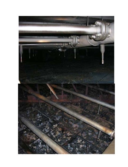
An example of how the improved cleanliness can make the maintenance easier and reduce costs is provided by a major refiner who recently decided to make a significant improvement in their vessel cleaning procedures. This included using a “new” vendor, whom they selected after an extensive evaluation process to improve their cleaning strategy and execution for a large vacuum column. Not only did they reduce the cleaning timeline by two days, but the resulting cleaning was also so complete they were able to cancel plans to replace the packing. The savings from that alone was worth over 3MM$ and saved two weeks of turnaround time. The two photographs at the end of the text indicate the post cleaning state of the column internals.
As a final point, we would recommend performing at least a short HAZOP or MOC review before conducting any new chemical cleaning procedure. It is also important to utilize an experienced vendor and to work closely with them throughout the entire process, from initial planning including modification of shutdown procedures to incorporate the nuances of the chemical cleaning process through final execution to help ensure a safe, successful, and on schedule equipment clean-out.
Jim Johnson (Marathon Petroleum)
Our decontamination procedures and practices have evolved over the years with the crude and vacuum units utilizing chemical cleaning to prepare the equipment for maintenance. One of our refineries has developed a practice that concentrates on flushing the residual oil from the system prior to addition of chemical resulting in a more effective chemical cleaning.
1.Rather than installing drain piping throughout the unit to tie into the slop system, all oil is water flushed to the crude or vacuum column where the water is subsequently drained to the sewer and the oil is pumped to the slop tanks utilizing the existing bottoms pumps.
2.The entire crude pre-heat and column side-draw circuits are water flushed to the column, with fire water connected to the appropriate pump suction. This provides a clean water flush rather than circulating oily water from the tower.
3.The chemical cleaning step follows the cold-water flush. On the crude unit water is circulated from the pre-flash tower through the heater and back to the pre-flash tower using the main fractionator bottoms pumps through the start-up circulation piping. The heater outlet is brought up to 250 degrees. Chemical is injected into each of the product draws and the water flush of each circuit is resumed. 4.After the water circulation, fresh water is used to flush the pre-heat exchanger circuit to the tower where the water with chemical and any recovered oil is pumped to storage to be processed through the WWTP later at a controlled rate.
5.As the side draw circuits have been water flushed, the water can be drained from all low points directly to the sewer without a detrimental effect to the WWTP.
6.The unit is then steamed out with steam introduced at the heater coils and at multiple locations on the column. The heater is re-lit with the outlet increased to 500 degrees for a final unit steam–out.
7.After verifying the unit is hydrocarbon free through ‘bomb tests and lab GC the tower is rinsed with cold water. An oxidizer is also used to reduce the potential for iron sulfide deposits to smolder.
Gregg McAteer (Nalco Company)
We are applying cleaning chemistry to towers and vessels and cutting normal steam-out time by approximately 2/3. The tower or vessel is then clean and saves further cleaning time so repairs can begin immediately.
Year
2010
Process
Question 51: In your experience, what are the implications on coker heater run length and coke drum operations with the following feedstock quality: Contaminants (Na, Ca), low saturates or high asphaltenes, crude compatibility, solvent deasphalt (SDA) pitch, low asphaltenes and high saturates?
Frank Tracy (ConocoPhillips)
I will first speak to the heater run length portion of the question and then to the coke drum operations portion of the question.
Heater Run Length
There are at least three main mechanisms under which the heater tubes become fouled:
•Inorganic material deposition or precipitation,
•Rapid asphaltene precipitation,
•Coke formation
All of these may contribute to chronic heater fouling. We link acute episodes of rapid fouling with the first two mechanisms.
1) We will begin with inorganic materials. Inorganic fouling more typically occurs in the upper radiant or even the lower convection section of the heater. These materials may be inherent in the crude or may be introduced during production, transportation or upstream processing of the oil prior to its arrival at the coker. Suspended solids in the oil are often a source of these inorganic materials.
The sodium and calcium noted in the question are certainly two that are common problems. 15-20 ppm sodium has long been the industry rule of thumb for a maximum limit for sodium in coke feed and one we use internally. Of course, we would like to see values below this range. Crude unit caustic injection for chloride control will contribute to the vacuum resid sodium load.
Silicon is an inorganic which has caused significant problems in at least three of our cokers. Silicon has been identified with certain crudes with the source most commonly being silicates and silica (quartz). Additionally, silicon-based anti-foam is suspected as a foulant in at least one case.
Iron is another inorganic we have seen cause heater tube fouling. Iron sulfides and other iron compounds enter with the crude and are not effectively removed in the desalter and end up in the feed to the coker.
There are other inorganics associated with fouling coker heater tubes and include aluminum and magnesium (associated with silicates) and barium. However, in our experience, these are less prevalent than the four previously mentioned.
Inorganic deposits often do not lend themselves to removal using online spalling or steam air decoking, and consequently, pigging must be used.
Ideally inorganic materials should be managed and minimized upstream of the coker. This may involve desalter operation, managing crude unit caustic injection, and addressing issues with crude suppliers. In addition, other streams fed to the coker such as FCC slurry oil and refinery slop oil can contain inorganic materials that may be detrimental to coker heater run length.
2) Asphaltene deposition is a second mechanism to watch for. We have experienced rapid, episodic fouling events due to asphaltene precipitation. This tends to occur in the upper radiant or lower convection section. It is sometimes linked to highly paraffinic resids or when the feed is a resid hydrocracker bottoms or deasphalter pitch stream.
Within COP we use asphaltene stability and proprietary coking propensity testing to evaluate feed stocks and identify and address problems with feeds or feed compatibility. ConocoPhillips proprietary Distillate Recycle technology, which recycles coker distillate through the furnace and coke drums, can also improve asphaltene stability.
3) Coke formation, the traditional heater tube fouling mechanism, is the third mechanism. The heaviest coke formation usually occurs in the lower radiant section where temperatures are the hottest. Turbulence and high velocity can be used to minimize the time any molecule is at the interface with the hot tube and are utilized to minimize coking. Velocity steam is used for this purpose. Distillate Recycle technology can also be used for this purpose, plus there is a yield benefit as well.
Drum Operations
Let’s shift to the second part of the question, which was how these factors effect drum operations.
Inorganic contaminants don’t have much impact on drum operations. However, for anode cokers, there could be coke quality implications with most of these contaminants.
Different feed stocks can have an impact on coke drum operation. The top of the coke bed has had the least amount of time to complete the coking reaction. If you have a less reactive feed stock, such as a hydrocracker bottoms stream, then that material in the top of the bed will be less converted to coke and more like tar than a traditional vac resid feed. This material is more likely to plug flow channels in the top of the bed and be less effectively quenched, which may result in more hot spots and blow outs.
We believe an increase in the amount of resid hydrocracker bottoms being fed to two of our cokers to be the reason for increased blowouts and have limited the amount of this material to help address this issue. We have also raised coke drum temperature to help complete the coking reaction.
Ralph Goodrich (KBC Advanced Technologies, Inc.)
With contaminates such as sodium and other salts the heater fouling is accelerated. This generally is related to a desalter upset or poor desalter operations. In extreme cases a desalter upset can cause the delayed coker to foul in a few days or less.
Caustic injection is a common practice to mitigate chloride corrosion problems in the crude tower and overhead system. However, the resulting sodium in coker feed can accelerate fouling in the delayed coker heater and should therefore be kept below 15 ppm. Thus, the caustic injection rates should be carefully monitored and kept to a minimum or eliminated if possible. Solids in the feed to the coker can also cause rapid fouling. For example, in some locations in Canada, the solids content is as high as 2 wt%. These extreme levels of solids will tend to cause fouling in the coker heater (the upper radiant and lower convection sections), fouling in the coke drum overhead vapor line, and main fractionator flash zone section.
High asphaltenes in the feed will also increase the furnace fouling rate. Furthermore, the high asphaltene content will tend to produce a shot coke, which in turn can cause drum cooling problems and high drum thermal stresses, ultimately resulting in drum cracks. Finally, there are definitely crude compatibility issues to be aware of. Dissimilar crude and resulting coker feeds can result in difficulties in drum cooling and hot spots - foaming can be an issue as well. Some of these problems with dissimilar coker feeds can be addressed with procedural changes but at some point, limiting the offending crude is the only economic choice. In general, to avoid these problems, keep the feeds to coker as similar as possible, i.e., do not mix highly asphaltenic feeds with highly paraffinic feeds.
Year
2010
Process


Question 74: Please discuss how yield data can be used to identify hardware issues. What hardware issues can you address to fix dry gas and benzene production?
Alec Klinghoffer (Coffeyville Resources)
There are several examples of how yield data can be used to identify hardware issues in the FCCU. For example, a decrease in cat to oil and/or catalyst circulation (which leads to a decrease in overall conversion and liquid yield) can be the result of a high regenerator dense bed temperature at constant process conditions. Several mechanical/hardware issues can contribute to higher regenerator temperatures. For example, higher regenerator bed temperatures can be the result of inefficient catalyst stripping and/or internal stripper damage. Entrained hydrocarbons are not sufficiently stripped and are burned in the regenerator causing an increase in bed temperature. Another mathematical check to this would be the H2 on coke calculation. Higher regenerator bed temperatures can also be caused by poor feed atomization and feed nozzle damage. The gas oil is not properly atomized and is “stuck” to the catalyst, causing a higher regenerator bed temperature as it is burned. This also causes a decrease in liquid yield and increased dry gas make. Another example of where yield data can be used to identify hardware issues is in the reactor. A decrease in gasoline yield and an increase in dry gas make could indicate an issue with reactor cyclones. If there is a hole in the reactor cyclones or reactor cyclone performance has decreased, catalyst can be trapped in the disengaging section of the reactor and re-react with the vapors, causing an “overcracking” of gasoline which leads to an increased dry gas make and lower gasoline yield.
Though not truly yield data, increased regenerator emissions (NOx, SOx) can be indicative of regenerator air grid pluggage or damage. This leads to poor air and catalyst distribution in the regenerator and decreased catalyst additive performance.
Here is a brief list of hardware issues to address to minimize dry gas make:
1.Catalyst stripper
a.Stripping steam nozzles plugged?
b.Stripper internal damaged or stripper upgrades needed because of higher catalyst flux rate limited?
2.Feed nozzles
a.Feed nozzles plugged, or feed not properly atomized because of feed nozzle design and limitations?
3.Reactor Cyclones
a.Holes in the cyclones or cyclones not designed for increased loading
b. “Overcracking” in the dilute phase causing an increase in dry gas.
Benzene production in FCC gasoline is influenced by catalyst choice, contact time and reaction severity. To reduce benzene, one could shorten the contact time in the riser and reactor dilute phase. Changing the feed location in the riser would shorten riser contact time and minimizing reactor dilute phase cracking would also reduce the benzene in CAT gasoline.
Year
2010
Process