
Question 19: In your experience, what are the effects on ULSD hydrotreaters when FCC operation is adjusted to maximize diesel?
Praveen Gunaseelan (Vantage Point Energy Consulting)
There are a number of approaches to maximize the diesel yield from FCC units, such as catalyst optimization, process modifications, and changing the FCC product cut points. These approaches can be used independently or in combination - the ultimate objective being to maximize the production of light-cycle oil (LCO) from the FCC unit for subsequent conversion to diesel.
Increasing the LCO content in the feed to ULSD hydrotreaters can significantly impact their operation. FCC LCO is generally of heavier gravity and higher in polyaromatic content and requires more severe hydrotreating than conventional ULSD feedstock such as straight run diesel. As a consequence, ULSD units that process increasing amounts of LCO may require higher operating temperatures – potentially reducing ULSD catalyst life – and consume larger amounts of hydrogen than conventional ULSD feedstock. FCC LCO also has the effect of lowering the ULSD product cetane number, and thus the fraction of LCO in the ULSD feedstock may have to be limited to conform to product cetane specifications.
Some of the adverse impacts of processing LCO in ULSD units can be mitigated by reducing the LCO gravity and polyaromatic content in the FCC unit. This can be accomplished by a number of approaches such as using tailored FCC catalyst formulations, increasing the severity of FCC feed pre-treatment, and appropriately lowering the LCO endpoint.
Dan Webb (Western Refining)
LCO becomes easier to treat when the FCC is adjusted to maximize refinery diesel production as Main column cut point changes are made to drop the back end of LCN into LCO. Not only does the LCO fraction become lighter, it also contains a higher fraction of less refractive (sterically hindered) sulfur compounds. The table below shows actual feed blend stock component analysis shifts in FCC max gasoline and max distillate modes.
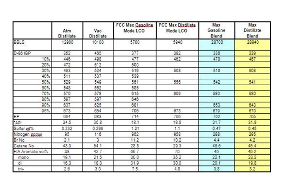
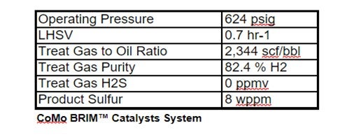
Haldor Topsoe used these actual component analyses to project DHTU catalysts performance. The following unit operating conditions were assumed to be constant.
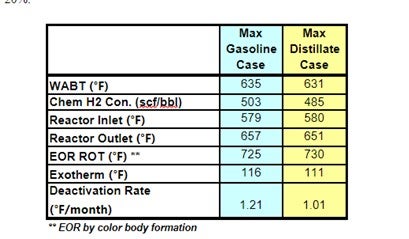
The projections below show that operating the FCC in max distillate mode produces a less severe DHTU feed stock: WABT is reduced by 3 -5 °F; 5-10% less H2 consumption; and catalysts deactivation may be reduced by as much as 20%.
Larry Kraus (Criterion Catalysts & Technologies)
Adding heavy diesel barrels to the feed to a ULSD unit will make the feed more difficult to process in terms of sulfur removal. Heavy feed barrels will also make it more difficult to ULSD products to meet T90 distillation specifications as defined in ASTM D-975. Mild conversion (mild hydrocracking) is sometimes employed in ULSD units to meet distillation specifications. If cracking cannot be utilized due to hardware limitations for naphtha handling or naphtha economics are not favorable, then aromatics saturation is the primary means to shift distillation The number of heavy barrels that can be added to the feed is then constrained by the ability of the unit to meet distillation specifications via aromatics saturation, and possibly cold flow properties. The combination of deeper aromatic saturation combined with heavier feeds containing longer paraffins both exacerbate diesel cloud and pour point, in many circumstances requiring further adjustment.
There are several routes to improve the cold flow properties of distillates. The addition of kerosene and / or cold flow improvers to the diesel pool is the most widely applied routes. Chemicals are effective for pour point and CFPP improvement but have little effect on cloud point.
The amount of kerosene blending is flash point constrained. Light material blending can have a negative effect on some product properties such as cetane and sulfur (if using untreated kerosene). The loss of kerosene in the diesel or heating oil pools is typically not an economically attractive option.
Another approach is to install a catalytic dewaxing unit to selectively reduce the cold flow properties of selected refinery streams or to revamp an existing ULSD unit to accommodate a bed of a dewaxing catalyst. In most commercial applications, catalytic dewaxing of diesel is carried out in single-stage, series flow configuration where desulfurization is carried out prior to dewaxing. Such processes involve base metal dewaxing catalysts usually in sandwich configuration below HDS catalysts, with the dewaxing catalyst being used under severe conditions (i.e., in the presence of H2S, NH3, unconverted organic nitrogen and sulfur-containing molecules). Alternatively, a two-stage configuration employing a noble-metal, second-stage catalyst can be used to provide isomerization / cracking dewaxing. Typically, two-stage dewaxing provides significantly higher yields of higher quality products.
Criterion Catalyst & Technologies and Shell Global Solutions have been involved in numerous projects over the last decade to revamp or build dewaxing capability in refineries that need mild to severe cold flow improvement in their diesel pool.
Sal Torrisi (Criterion)
In maximizing LCO from the FCC, this typically means increasing primarily the LCO and also the HCN volume. We observe that these streams get less aromatic and have a higher API, in many circumstances due to a decrease in conversion or cracking intensity. The combined changes in volume and quality of LCO and HCN can have measurable impact on operation of the ULSD unit as described below:
- Desulfurization Performance – In general, the percentage of difficult sulfur species in LCO as well as the nitrogen content goes down as the volume is increased. If the LCO volume in the ULSD unit remains constant, then the feed blend can be easier to process, however it is a more likely scenario that the extra LCO is processed in the ULSD unit. The net performance of a higher volume of slightly easier to process LCO usually means higher temperature requirements, higher deactivation rate and shorter HDS catalyst life.
- Hydrogen Consumption – More, but less aromatic LCO, will still result in an overall increase in hydrogen demand for the refinery. If the LCO is to be upgraded into diesel, it will need anywhere between 600-1600 SCF/B of hydrogen depending on the operating severity of the ULSD unit. For newer, high pressure ULSD units having ample makeup and recycle hydrogen, this is usually a minor issue. For moderate pressure units, the extra volume of LCO may be a challenge to handle both from a hydrogen supply standpoint as well as from an operation standpoint. See deactivation comment.
- Catalyst Deactivation – Two of the variables that correlate strongly with catalyst deactivation are the quantity of polyaromatics passed across the catalyst and the hydrogen partial pressure. As the LCO rate goes up, so will the polyaromatic coke precursors. In addition, as the hydrogen consumption increases, the subsequent hydrogen partial pressure throughout the system will decrease. The combined effect of these changes can be a measurable increase in catalyst deactivation rate.
- Product Quality – With less aromatic LCO, the cetane of this component will increase. However, the increased quantity of LCO will typically overwhelm this higher LCO cetane to cause a lower overall ULSD unit feed cetane number. If the refinery diesel pool is not cetane constrained, then this is not an issue, but many refiners are pushing cetane limits today and even require additives to make specifications.
If the increased volume of LCO pushes the ULSD operation into a unit constraint, there are ULSD catalyst options available to manage cycle length, hydrogen consumption and even product quality, enabling refiners to maximize diesel volume by incorporating more of these challenging FCC products into the diesel pool.
Brian Watkins (ART)
Increasing the quantity of heavier boiling fractions (LCO, Coker, Light Gas Oils) to the diesel hydrotreater has a number of impacts both on the performance of the hydrotreater and on the resulting ULSD product properties. Higher boiling fractions typically increase the amount of hard sulphur compounds, as well as increasing the amount of nitrogen and complex aromatic species. This has the combined effect of lowering the product cetane and limiting end of run (EOR) by making it difficult to maintain diesel ASTM color. Since general hydrotreating reactions do little to shift distillation, only a small quantity of higher boiling materials can be placed into the pool to maintain the product distillation specifications.
With the use of a selective ring opening (SRO) catalyst as part of the catalyst charge ART is able to improve diesel product cetane numbers by reducing total aromatic and PNA levels. The addition of SRO catalyst also helps provide additional EOR life in terms of product color. A catalyst system utilizing a high activity NiMo (NDXi) coupled with a selective ring opening catalyst will provide the same HDS and HDN activity, while having the ability to process additional LCO and other higher boiling fractions as well as achieving higher aromatic saturation conversion compared to the hydrotreating catalyst alone.
The new SmART Catalyst System® with SRO catalyst capability is very effective for reducing aromatic rings found in heavier feedstocks providing improved cetane and color performance. The majority of this increase in traditional cetane upgrading is due to the saturation of poly aromatic compounds with some moderate amount of mono aromatic saturation. Saturating aromatic rings is an effective way to improve cetane, but there is a practical limit to the amount of cetane uplift that can be achieved. The reaction becomes thermodynamically limited near the end of the cycle resulting in a much lower level of cetane uplift and possible color problems. A better approach is aromatic saturation followed by selective ring opening. The resulting product has a higher cetane and lower aromatic and boiling point and avoids the issue of thermodynamic control at the end of the run. Additional information on this process can be found in the NPRA paper AM10- 166.
Advanced Refining Technologies (ART) is well positioned to provide assistance on how best to maximize unit performance and to take advantage of opportunities to successfully process more complex feeds into the ULSD pool. ART has developed catalysts specifically designed to handle more difficult feeds exemplified by the SmART technology for ULSD. The technology has been widely accepted and the addition of an SRO catalyst to the ULSD catalyst portfolio provides refiners with greater flexibility in the operation of their diesel hydrotreating units.
- Product Quality – With less aromatic LCO, the cetane of this component will increase. However, the increased quantity of LCO will typically overwhelm this higher LCO cetane to cause a lower overall ULSD unit feed cetane number. If the refinery diesel pool is not cetane constrained, then this is not an issue, but many refiners are pushing cetane limits today and even require additives to make specifications.
Year
2010
Submitter
Process
Question 20: How do refiners quantify the impact of sodium on hydroprocessing units, specifically those processing either residuum or VGO feeds?
Dan Webb (Western Refining)
Sodium generally enters a hydrotreater due to upstream addition of caustic soda or desalter operational problems. Feed sodium content of more than 3-5 ppm should be avoided. Sodium has a significant deactivation effect; 1-3 %wt results in a 50% loss of catalyst activity. The deactivation mechanism is by blocking of acid sites and a reduction in the cracking function. Also, sodium penetrates the entire pore structure of the catalyst; and, when combined with water, can weaken the catalysts support structure causing breakage and high pressure drop. Sodium promotes catalysts sintering during regeneration. Catalysts containing more than 0.25 %wt sodium are not suitable for regeneration.
Brian Slemp (CITGO)
Prior to VGO reactor loading, CITGO projects the level of feed containments and we work with the catalyst vendors to customize the reactor catalyst system metals trapping capacity to achieve the desired run length with maximum value creation. We monitor our feed sodium along with other feed contaminants and estimate the projected level of metals trap saturation. Post reactor dumping, we validate the saturation projection via spent catalyst testing and modify the next catalyst system based on the spent catalyst contaminants level and the anticipated future feeds. As a side note, our historical observations show the feed testing indicates a higher level of sodium contamination than the spent catalyst testing validation. We also monitor our reactor products for indication of metals trap breakthrough such as increased light ends production and loss of volume swell as compared to design.
Vern Mallett (UOP)
Sodium usually enters a hydrotreater as a contaminant from improper desalter unit operation and/or caustic addition in the crude tower to neutralize high TAN feed stocks. Sodium adversely impacts the performance of all hydrotreaters so removing it from the feeds to the hydrotreater is the best solution. Nonetheless, upsets or specific crude runs may introduce enough sodium to VGO or residue hydrotreaters to cause a reduction in performance. Sodium predominantly affects HDS, HDN and HDA reactions. HDM and HDCCR are less affected. Thus, preventing sodium migration from the top bed and guard catalyst to the main active catalyst is important to maintain unit performance as long as possible.
In fixed bed units, Na can deposit both on the catalyst particle surface and within the catalyst pore structure of VGO and residuum hydrotreating catalysts. When depositing on the surface and interstices, the result is likely to be pressure drop build-up while deposition inside the particle generally results in reduced activity. Spent catalyst may accumulate 10 wt% or more of Na when deposited internally, depending on catalyst type and structure. Na is generally observed as Na2S crystals and in combination with Fe as FeNaS crystals. 1 wt% of Na deposited within the catalyst reduces activity by 10-20% and 5 wt% Na on catalyst results in 40-50% activity reduction.
Catalysts with high Na are unsuitable for regeneration since the heat treatment required to remove coke deposits allows the Na on spent catalyst to react with the alumina support. Surface area is drastically reduced during regeneration of high Na containing spent catalyst resulting in very low activity recovery.
Kevin Carlson (Criterion Catalysts & Technologies)
The refining and catalyst industry generally consider sodium to be an adverse feed contaminant resulting in catalyst fouling and deactivation. Criterion as well as other major catalyst developers continues to advise their client base to be aware of the potential impacts. Na can naturally come from crude oil or can be present in aqueous emulsion with the oil. Sodium affects catalyst activity within the cycle in which it is deposited as well as limiting the regeneration of Na contaminated catalyst for reuse. Presence of 1% Na2O on spent catalyst has been shown to reduce activity by more than 50%. It is recommended that efficient operation of desalting units is maintained, and regeneration is not recommended for spent catalysts containing more than 0.25% of sodium.
Data available on catalyst activity affected by deposition of sodium within the same cycle in which it was deposited is rather limited, making “quantification” of the impact difficult. In most of cases Na is carried into hydroprocessing units by aqueous emulsion with the feed. Sodium tends to deposit in the upper portion of the catalyst bed that can result in a crust that increases pressure drop and adversely impacts reactor flow distribution.
Greg Rosinski (ART)
Sodium (Na) is a severe catalyst poison that can cause significant activity loss even at low levels. It works by promoting the sintering of catalytic metals and neutralizing acid sites. Typical sources of sodium include a malfunctioning de-salter, sea water contamination or caustic contamination. Depending on the source of sodium, the signs of poisoning include rapid activity loss and an increase in pressure drop. The figure below shows the impact of sodium poisoning on catalyst activity.
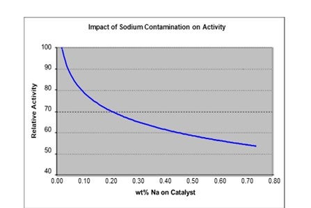
The figure indicates that for a sodium content of 0.5 wt% the activity is at most 60% of fresh catalyst activity. This translates to roughly 30°F loss in activity for 1 wt% sodium on the catalyst
Year
2010
Process
Question 21: Silica uptake on gas oil and diesel hydrotreating units is an increasing problem. In your experience, what is the source of silica in these feeds? Do you have effective ways to manage this silica?
Vern Mallett (UOP)
The main source of silicon in Hydrotreaters is polysiloxane compounds (such as polydimethylsiloxane) used to control foaming in delayed coker units. It has also been reported that indigenous silicon is present in some heavy oils. Silicon may also be introduced to crude as a component of some drilling chemicals. Synthetic crude blends may include appreciable silicon as a consequence of the upgrading and production methods.
Under the high temperature conditions of a delayed coker, polysiloxane is thermally decomposed to silicon containing molecules of varying chain length. Siloxane molecules in the naphtha boiling range account for approximately 70% of the silicon in coker liquid products. The remaining silicon is distributed in the distillate and VGO fractions at around 15% each. The siloxane chain length increases with boiling range and this impacts the effect on hydrotreating catalysts. It is well known that silicon capacity of coker naphtha catalysts is proportional to surface area and spent catalyst analysis shows relatively uniform distribution of silicon throughout the catalyst pore structure. The same deposition observations hold true for siloxanes in distillate units. We observe different behavior in VGO units where apparently siloxane chain length is high enough to affect diffusion rate into catalyst pores. In VGO units it is not uncommon to observe high levels of silicon collecting on the surface of the hydrotreating catalyst, creating a kind of crust, often in combination with iron.
Depending on the feedstock, the countermeasures to the effect of silicon vary. In the naphtha and distillate fractions, use of high SA guard and main bed catalysts prevent breakthrough for the maximum period. In VGO units, a large pore diameter material with lower SA may be more effective at removing silicon. It's worth noting that the combination of lower LHSV and lower siloxane content in distillate and VGO feed stocks, as compared to naphtha feeds, makes it much easier to prevent silicon from progressing deeply into the reactor.
Brian Moyse (Haldor Topsoe)
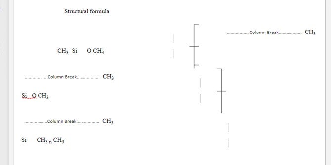
Initially, we must examine the terminology
Silicon : The element Si, Mwt ~28
Silica : Silicon dioxide SiO2, Mwt ~60
Silicone : Polymers based upon repeating units with SiOR2
Typically Poly Di-Methyl Siloxane PDMS (Figure 1)
So, in our business, we typically talk about silica SiO2, because this is often what we actually measure in spent catalyst samples.
Today, silicon enters the oil refining system via a number of widely differing routes:
Oil Production
Crude oil
Water injection (enhanced recovery)
Utility systems (heating, gas scrubbing)
Downhole operations (drilling, cementing)
H2S/CO2 removal systems
Refineries
Delayed coking (antifoams – PDMS) Gas scrubbing
Wastewater treatment Fuels
Terminals
Crude oil
Wastewater treatment
So, we can see that for hydrotreater feedstocks, there are a number of possible sources for contamination by silicon. Historically, most of the silicon encountered in the refinery comes from the use of antifoams like PDMS used in delayed coking units.
When exposed to temperature, PDMS breaks down into fractions (Figure 2). So, depending on your cut point, although most of the silicon will be in the naphtha cut, some will also be encountered in the diesel and heavier gas oil fractions.
Figure 3 shows the impact of silica (SiO2) on catalyst activity. For silicon, the values on the X axis should be halved.
It is interesting to note that silicon deposition affects the HDN function more than the HDS activity.
As far as silicon pickup capacity of catalyst is concerned, there are a number of factors to be considered. First is that the actual deposition of Si is diffusionally-limited for catalyst particles larger than 1/20", so less-than-ideal pickup of Si will be experienced in 1/8" or 1/10" particle sizes.
There is also a function of catalyst surface area. The more surface area, the greater the capacity to pick up silicon.
From this, we can see that high surface alumina with no metals would have the greatest silicon pickup but, of course, would have no activity for HDS or HDN.
Finally, there is an effect of reactor operating temperature. Silicon pickup on catalyst increases with operating temperature, and pickup can double by increasing temperature from 500-600°F.
Properly formulated Silica tolerant hydroprocessing catalysts are capable of picking up 25 - 30% by weight of silica or 12 - 15% by wt of silicon.
Figure 1
POLYDIMETHYLSILOXANE
SYNONYMS Poly(dimethylsiloxane),dimethylpolysiloxane, dimethylsilicone fluid,
dimethylsilicone oil; INS No. 900
DEFINITION Consists of fully methylated linear siloxane polymers containing repeating units of the formula (CH3)2SiO, with trimethylsiloxy end-blocking units of the formula (CH3)3SiO-
Chemical names Simethicone (CAS name)
C.A.S. number 8050-81-5
The average value for n is 90 to 410
Formula weight 6,800 to 30,000 (average and approximate)
Assay Silicon content not less than 37.3% and not more than 38.5% of the total
DESCRIPTION: Clear, colorless, viscous liquid. Polydimethylsiloxane is frequently used in commerce as such, as a liquid containing 4- 5% silica gel, and as an aqueous emulsion formulation containing, in addition to silica gel, emulsifiers and preservatives. The pure substance described here can be isolated by centrifuging from the silica gel-containing liquid at about 20,000 rpm.
FUNCTIONAL USES: Antifoaming agent, anticaking agent
 Decomposition of PDMS
(Boiling Point of PDMS Fractions)
Product b.p. °F
Cyclic D3 273
Cyclic D4 349
Cyclic D5 410
Cyclic D6 473
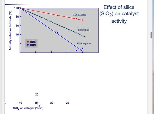
Figure 3
Geri D’Angelo (ART)
Silicon typically can be found coming from two locations in the refinery. Refiners having a coking process which requires antifoam usage generally see high concentrations of silicon in the naphtha and other light cuts from these units. Recently, refiners have been observing an increase in silicon levels coming from the crude tower and have begun to trace this to synthetic and other crudes new to the refinery. The process of making synthetic crude often involves a coking process, as well as other agents and antifoams added to the final product for ease of transport. Many different crude suppliers have been found to use additives containing silicon for the crude drilling process, and pipeline companies are using silicon containing additives injected into the crudes for both flow enhancing performance and foaming issues. The silicon tends to concentrate into most of the lighter cuts in the refinery including naphtha, kerosene, diesel and some gas oils. We’ve seen many of these types of units processing a feed directly from the crude unit which used to run for years between catalyst change outs, and now they shut down every 1-2 years due to silicon poisoning. The units did not have any guard catalyst installed as the refiners were not expecting silicon in a feed from the crude tower.
Some of the crude suppliers and pipelines have agreed to look into using different chemicals and technologies to decrease the amount of silicon ending up in the synthetic and other crude types. Progress in reducing the silicon values have been made by some of the suppliers which has been confirmed by the refineries. The reductions of the silicon values have been as high as 400%.
The most effective way to manage the silicon, assuming it can’t be removed from the feed slate, is to use a silicon guard catalyst near the top of the reactor to protect the main bed catalyst from poisoning for as long as possible. ART offers two catalysts which are effective at trapping silicon. AT724G is a high surface area silicon guard which has silicon pick up of capacity 20 wt% Si. Even higher levels of pickup have been observed in units which operated at higher temperatures. ART also offers AT734G which is a combined silicon and arsenic guard. It has a silicon capacity similar to AT724G with 4 times the arsenic capacity. Both AT724G and AT734G also have moderate activity and are used for activity and size grading at the top of the catalyst bed.
Year
2010
Process
Question 22: In your experience, how are ULSD units maximizing catalyst life/ cycle length? Do you use feedstock or catalyst analysis to locate sources of contaminants, especially arsenic?
Brian Moyse (Haldor Topsoe)
Many factors impact the cycle length in a ULSD unit, and in order to ensure the longest possible cycle length in such units it is important to:
Have an optimal flow distribution and gas mixing using latest generation reactor internals designed for the actual operating conditions. This is very important in order to ensure maximum catalyst utilization with no channeling in the catalyst bed.
Ensure hydrogen availability all through the reactor using optimum flow rates and quenches. Hydrogen is not only used for the hydrotreating processes, but also to minimize coke formation and thus lower catalyst deactivation rate.
Optimize the quench injection and rate to ensure the lowest possible WABT throughout the run as higher temperature will accelerate coking rates.
Have a complete feedstock analysis and composition, in particular the organic feed nitrogen. Organic feed nitrogen plays a key role for catalyst performance. It is not only important to know the feed nitrogen, but also the catalyst’s ability to lower the organic nitrogen. The level of nitrogen in the product dictates the optimal catalyst for the given service, be this CoMo, NiMo, or a high activity HDN catalyst.
CoMo catalysts perform best if organic feed nitrogen is high, and product cannot be reduced to 1-2 ppm level. A NiMo, high activity HDN catalyst is the optimal catalyst if product nitrogen can be reduced to < 1-2 ppm N.
Select the appropriate catalyst for the given operating conditions. If the right catalyst choice is made, it can operate at the lowest temperature and thus ensure a long cycle. Failure to achieve this will result in a catalyst load which will suffer a rather fast deactivation rate. Also, catalysts containing any elements that improve the HDN activity will have a tendency to deactivate faster if they are not able to lower the feed nitrogen to very low levels under the actual process conditions. This is often the case where the feed blend contains cracked stocks like cycle oil, coker gas oil, etc.
Feed impurities that contaminate and deactivate catalysts must also be addressed and removed. Typical elements are V, Ni, Fe, P, Si and As; and these will deactivate the high activity catalysts in different ways. They can however be trapped in a well-designed grading or in specific traps which are optimized for contaminant pickup to protect the high activity downstream catalysts.
Typically, Haldor Topsøe uses feedstock analysis to identify and quantify feed contaminants such as described above, (feed nitrogen, V, Ni, Fe, P, Si and As). Arsenic (As) is known as a very strong catalyst poison, even in ppb levels. To quantify Arsenic content new techniques, have to be applied to quantify the ppb levels in order to be able to properly design the optimal grading/trap solution. We also use spent catalyst analyses when these are available from previous cycles, as this will help support the feed analysis.
Vern Mallett (UOP)
This is a two-part question the first part being maximizing catalyst life/cycle length, and the second being feed contaminants.
Part 1: Regarding maximizing catalyst life/cycle length. This will greatly depend on several factors mainly economic on how a ULSD complex or individual unit is optimized. Economic decisions within the organization dictate the operating conditions necessary to achieve product yields and properties, what feed components are processed in the unit, balanced with getting the optimum performance from the catalyst. This balance is challenging from an economic and operational aspect. The need to maximize margins by processing higher than design raw feed rates and heavier feed components, is resulting in a more exact monitoring of the catalyst performance. Refiners are operating units with higher than design reactor catalyst bed axial rises, and radial temperature spreads, as units process a wider range of feed components.
Expected catalyst life is also closely linked to refinery turnaround schedules for other processing units, which presents challenges on how best to optimize catalyst performance and still achieve the desired cycle length to coincide with refinery wide turnaround schedules.
Part 2: Regarding using feedstock or catalyst analysis to locate sources of contaminants especially arsenic. In order to identify the source of contaminants a monitoring program must be established designed to separate components that may be contributing to the contaminant issue(s). These components are usually but not always the individual feeds that a unit is processing. The first phase of a program is generally centered on the feeds that are being processed in the unit. Other sources of contaminants such as scale or FeS may enter into the unit from upstream processing equipment and fractionation within the hydroprocessing unit itself, which will contribute to catalyst bed pressure drop or increase maldistribution and depending on type and accumulated amount of the scale can contribute to loss of catalyst activity. It is important to understand what contaminant or accumulation of contaminants is causing the issue. Catalyst activity loss can be attributed to many factors. Metals such as Nickel and Vanadium are common in nearly all raw feed stocks that are processed in a hydroprocessing unit, whereas Arsenic at one time not as common is now found in most crude and feed stocks and is contributing to the deactivation of catalyst. Silicon, Sodium, and other exotic contaminates are now more commonplace. One of the successes of an analysis program is the correct laboratory testing methods be used. Second is having a broad approach to identifying contaminants, there may be one or a combination of several contaminants that will contribute to either catalyst performance or catalyst bed pressure drop increases. It is also important that the analysis program take into consideration the full feed processing range in order to ensure that all the feeds being processed are being analyzed.
Analyzing spent catalyst once the catalyst has been removed from the unit, does not necessarily determine where a contaminate source comes from. The catalyst analysis does identify the various contaminant components that contribute to either the loss of activity or to the increase of catalyst bed pressure drop. Catalyst sampling is very important when identifying contaminants. The information gained will benefit the design of graded bed catalyst systems for possibly the next cycle to help mitigate the impact of contaminates. The spent catalyst analysis combined with the analysis of the various streams coming into the unit will provide a broad outline of the source of contaminates and also specify accumulated amounts of contaminants that are being deposited on the catalyst.
Sal Torrisi (Criterion Catalysts & Technologies)
After the first one or two ULSD cycles, some refiners have learned a few additional ways to squeeze a little more performance out of each run relative to the original plans.
•Using multiple catalysts in the same reactor system to maximize performance – custom catalyst design to balance contaminant protection, HDS, HDN and aromatic saturation (H2 consumption). Many of the ULSD units have migrated from a single CoMo or NiMo catalyst in the first cycle to a two or three catalyst system in the subsequent cycles, creating opportunities to maximize cycle life and processing capability
•Altering operating temperature strategy – multi-bed ULSD units can operate with much different temperature profiles depending on quench and furnace capabilities. In order to keep some of the catalyst in a favorable hydrogenation regime not only to minimize coking/catalyst deactivation but also to maximize HDS, particularly at EOR conditions.
•Taking full advantage of maximum EOR temperatures – Typical EOR is defined by one of three limits: ability to make product sulfur target (kinetic or thermodynamic limitations), to achieve product color or to fire furnace harder. Many refiners have done test runs toward the end of run to probe which limitation they will hit first, finding that they can go 5-15 °F higher in operating temperature than previously anticipated. This can give an additional 1-6 months of cycle length depending on the individual unit feeds and conditions.
•If a refinery produces ULSD from multiple hydrotreaters or hydrocrackers, there may be an opportunity to adjust product specification on an individual unit to optimize combined cycle lengths for each unit. If these units change catalysts at different intervals, there may be an opportunity to relax sulfur specification for a ULSD unit as it approaches EOR conditions, particularly if another ULSD unit or hydrocracker is near SOR conditions during the same period. In addition, advanced control systems have been implemented in some locations to utilize unit on-line sulfur analyzers to minimize overtreating, product giveaway and maximize cycle length.
•Optimizing cut points of individual feed components, because the desulfurization reactivity and deactivation behavior for incremental diesel from different streams/crude sources can vary significantly. The 650-750°F boiling range from SR, Coker, LCO and other diesel streams usually contain not only varying amounts of refractory sulfur, but also nitrogen and polyaromatics that largely determine operating temperature and catalyst deactivation rates. Catalyst cycle length and diesel volume can be maximized for a given refinery operation by investing time to evaluate in detail the incremental heavy diesel barrels from each component and their subsequent impact on the ULSD operation.
David Krenzke (ART) ULSD units are maximizing cycle by controlling several critical operating parameters including:
•Hydrogen partial pressure: Hydrogen purity and recycle gas rate need to be maintained at target levels to minimize coke formation. For ULSD operations, ratios of hydrogen consumption to hydrogen to oil in excess of 5 to 6 provide greater stability and optimum performance of the catalyst.
•Feed distillation: The feed end point has a significant impact on the required temperature to meet a product sulfur target. Increases in feed boiling point quickly increase the concentration of hard sulfur as well as increasing nitrogen and PNA levels. A high-end point tail on the feed distillation will reduce the temperature span between SOR and EOR by requiring a higher WABT to produce the same product specifications, which in turn increases the deactivation rate as well as increasing hydrogen consumption.
•Sulfur conversion: Over-conversion even by 1 or 2 ppm can significantly increase the catalyst deactivation rate. Higher temperatures to produce a lower product sulfur than needed increase coke deposition causing a higher rate of deactivation. Some refiners are using closed loop control with an on-line product sulfur analyzer to maintain on-spec product to prevent over-conversion.
•Feed composition: Higher concentrations of cracked stocks (coker & LCO) increase the concentration of hard sulfur which requires higher temperatures to remove. Cracked stocks also increase the olefin and PNA concentrations in the feed resulting in an increase in hydrogen consumption, higher exotherms and lower outlet hydrogen partial pressure. The net effect is a shorter cycle length due to higher operating temperatures and an increase in deactivation rate.
•Consistent feedstock analysis is important to determine the presence of contaminants which can significantly impact catalyst life. Some of the more common ULSD catalyst poisons are Silicon and Arsenic. These can be difficult to detect in the feed at low concentrations and may also occur intermittently depending on the feed source.
•Spent catalyst analysis: a post mortem on spent catalyst is a useful way to detect the presence of unexpected contaminants and helps to optimize subsequent catalyst loadings in the unit. A good way to determine the average concentration of poisons like arsenic and silicon is from an analysis of spent catalyst from various locations in the reactor. Once the concentration is estimated an appropriate catalyst loading with guard materials can be utilized.
Year
2010
Process
Question 23: The liquid recycle rate to a second stage of a hydrocracker can shift conversion, light end yields, cycle length and/or the required temperature to achieve a desired conversion. What strategies do you employ to reach optimum conditions
Vern Mallett (UOP)
In two-stage hydrocracking design there are several variables that need to be balanced for optimum performance. Desired product yields or selectivity can be affected by conversion per pass in each stage. Lower conversion per pass is desirable to maximize heavier product selectivity. Fixing first-stage conversion. Conversion per pass in the second stage can be lowered by increasing the liquid recycle. Increasing the recycle rate lowers conversion severity but increases space velocity and reduces treat gas rate for the second stage catalyst. This has a detrimental effect on catalyst life but lower conversion per pass reduces severity lowering the catalyst deactivation rate, however too low of a conversion will affect product qualities adversely. For optimum conditions one needs to consider unit design conditions like H2 partial pressure, feed quality, minimum product quality requirements and catalyst life objectives. Strategy for optimum conditions would be to increase liquid recycle within the hydraulic limit of the unit and lower conversion severity in the first stage to the point where catalyst life, product quality or increased operating cost become an issue.
Year
2010
Process
Question 24: For a hydrocracker with a debutanizer/stabilizer column, what corrosion issues do refineries experience in the feed and/or overhead systems? What have you done to mitigate the corrosion? What are your key considerations in optimizing these parameters
Vern Mallett (UOP)
This answer assumes that the Debutanizer column is the first fractionation column design. In such columns, corrosion of the column bottoms, bottom outlet piping, reboiler tubes, fractionator feed heater tubes and the downstream fractionator is possible due to poor stripping of H2S. A minimum amount of vapor must be generated in the Reboiler to get sufficient V/L traffic below the feed tray for adequate H2S removal. The problem is that the relatively heavy Debutanizer bottoms liquid must be boiled to generate the stripping vapor. At the operating pressure of the Debutanizer, this can generate quite high Reboiler outlet temperatures. Also, it is not easy to determine how much vapor is being generated. If the Reboiler firing according to the outlet temperature, does not ensure sufficient vapor generated, because this will depend on the distillation curve adjusted for the operating pressure. The bottom line is that H2S stripping is very inconsistent, particularly for upset conditions. The result is corrosion in the equipment and systems mentioned above. It has been found beneficial, particularly for maximum distillate units to recycle some light naphtha to the Debutanizer feed in order to keep sufficient light material in the column bottoms so that sufficient vapor can be generated at a reasonable Reboiler outlet temperature. It is also recommended that bottoms piping, Reboiler tubes and fractionator feed heater tubes be at least 9% Cr material and the downstream fractionator should be lined up to the diesel draw tray. It may also be necessary to line the top of the fractionator because of the possible occurrence of a wet H2S environment, particularly for a steam stripped fractionator.
Michael Chuba (Sunoco)
Our Hydrocracker is configured with a preflash column followed by a main fractionator which fractionates out the light and heavy hydrocrackate. Originally the preflash tower was designed with a thermosyphon reboiler driven by a hot oil circulation system. This thermosyphon reboiler had historical problem with iron sulfide fouling which resulted in significant heat transfer loss and inability to properly strip the bottoms material feeding the main fractionator. This under-carry of H2S would lead to not only corrosion issues in the overhead system of the main fractionator, but also trace amounts of H2S in the hydrocrackate streams feeding the catalytic naphtha reformers.
To mitigate this problem a project was implemented to convert the thermosyphon reboiler to a forced system. Bottoms recirculation pumps were installed and the reboiler exchanger service was switched from having the process fluid on the shell side to tube side. This prevented any corrosion material from lying down and fouling the shell side. In addition, this modification allowed for a more stable control of heat input to the column since both the circulation rate and reboiler return temperature could be more finely controlled.
Since commissioning of the system, significant improvements in the preflash tower operation have been observed. The fouling of the reboiler, which in the past would limit capacity and result in H2S under-carry, has been significantly reduced.
Paul Fearnside (Nalco Company)
The hydrocracking debutanizer/stabilizer corrosion issues are determined by how well the upstream water wash is performing in minimizing the amount of corrosion precursors and carryover into the debut/stabilizer. The main corrosion mechanisms are driven by ammonium bisulfide, cyanide, and wet H2S. Less frequently, upstream oxygenated wash water has been the culprit. Determining which corrosive is involved is key to what mitigation strategy is used. Most common is a filmer, with a slipstream, injected into the debut/stabilizer OVHD vapor line. Less common is an oxygen scavenger into the upstream water wash.
Sam Lordo (Nalco Company) Typical anticipated corrosives in these tower overhead systems are NH4HS, Nh4Cl, Wet H2S, and Cyanide. Protection can be addressed using metallurgy, waterwash upstream or in the tower ovhd circuit, and chemical additives such as, filming amine corrosion inhibitors, metal passivators and salt dispersants. A good monitoring program supported by water analysis and corrosion probe or other corrosion monitoring methods (i.e., UT, RT, H2 permeation, etc.)
Question 25: Besides high reactor temperatures and flow maldistribution, what are other causes of high gas and LPG yields in a hydrocracker have you experienced?
Praveen Gunaseelan (Vantage Point Energy Consulting)
Hydrocrackers typically process heavy gas oils into distillate-range material. The gas oils are catalytically cracked at high pressures in the presence of hydrocracking catalyst and hydrogen. The reaction is exothermic and consumes a relatively large quantity of hydrogen. High gas and LPG yields would be generally undesirable in a properly operating hydrocracker.
In addition to high reaction temperature and flow maldistribution, there are various other potential causes of high gas yields in hydrocrackers, some of which illustrated below:
•Deviations in feed composition and properties
·Increase in the light content in the feed
·Decrease in the feed pressure
·Increase in the feed temperature
·Changes in the gas/liquid recycle ratio
•Deviations in the reaction process
·Excessive cracking (e.g., high catalyst activity, high recycle rate, etc.)
·Loss of selectivity (e.g., due to catalyst aging)
·Catalyst-related issues
·H2-related issues (e.g., drop in H2 partial pressure)
Brian Slemp (CITGO)
•Light material (naphtha) in feed.
•Light material (naphtha) in recycle oil.
•High % of recycle oil back to reactor (or really, most things that increase conversion).
•High catalyst activity - high activity overcracks; low activity needs an increase in temperature causing more thermal cracking.
•Poor catalyst selectivity.
•Low H2 PP in recycle gas causes coking and light ends generation.
•Low recycle gas to liquid rates - higher residence time on catalyst, consumes H2, and drops the H2 PP, causing coking and light ends generation.
•Uneven temperature profile across each of the cracking beds.
•Catalyst poisons/contamination.
Ward Koester (Zeolyst International / Criterion Catalysts & Technologies)
Several different factors can increase production of lights ends in hydrocrackers. These include changes in makeup gas quality, feed poisons, changes in liquid feed type, increased reactor operating severity, and thermal cracking due to hot spots in either upstream furnaces or reactor catalyst beds.
The amount of C1 and C2 introduced with fresh gas determines to a large extent the recycle gas content. Formation of C1 and C2 due to cracking reactions is only a few tenths of a percent. Due to its low solubility in oil, C1 in the recycle gas can increase by more than 5 times the m/u purity. The amount of C1 can be managed by purging. CO and CO2 are impurities that can convert to methane and water through the methanation reaction which is highly exothermic and consumes hydrogen. The CO and CO2 will reduce catalyst activity due to competition for active reaction sites resulting in higher temperature requirements to maintain conversion, resulting in increased LPG production.
It is important to measure recycle gas composition on a regular basis, and to trend the results. If all else is constant, an increase in methane content could be due to the growth of a hot spot. Catalytic conversion will produce very little C1, some C2, and mainly C3 and C4. Thermal cracking, however, can generate significant amounts of C1 and C2. Note: even if you have a lot of thermocouples, you may not see a hot spot. Strictly speaking, it is impossible to see the highest temperature in a bed. If the reactor outlet temperature is higher than any individual last-bed temperature, you should be worried, even if your measured radial ∆T appears to be ‘acceptable.’
Catalyst poisons such as silicon, arsenic, and sodium can affect the activity and selectivity of the catalyst, resulting in higher required temperatures and increased gas and LPG production.
Changes in feed quality will influence product selectivity. C4-minus can increase when the feed gets much lighter or when it becomes more difficult to crack. Increasing the amount of a refractory blendstock, such as a feed with a higher endpoint (maybe due to resid entrainment), a pre-hydroprocessed material, or desulphated oil increases the temperature required to maintain a given conversion. This will increase production of C4-minus. Conversion that occurs in the pretreat section is also affected by feed quality. As with the cracking section, for a more refractory feed or a feed with a higher nitrogen content, keeping the same nitrogen slip requires higher temperatures. Replacing straight-run material with cracked stocks, such as LCO, coker gas oil or coker naphtha, increases pretreat-section temperature rise, which can increase non-catalytic conversion.
Lowering the recycle cut point at constant gross conversion (constant bleed oil rate) will increase the severity of the cracking operation resulting in a lighter product package with more LPG and gas.
Excessive local heat flux in furnace tubes creating very high local film temperatures can cause thermal cracking producing increased amounts of C1 and C2. Typically, this is not a big issue because the residence time in the “film” is very short, assuming good turbulent/plug flow in the furnace tubes. However, at certain operating conditions like EOR turndown, it could be more of a factor. Also, this phenomena cures itself as the local hot spots tend to get an insulating layer of coke built up on them which will periodically slough off (especially during unit upsets) and allow the process to repeat.
Year
2010
Submitter
Process