Director, Petrochemical Policy
AFPM employees combine both in-office and remote work into their schedules using up to 6 remote workdays a month. Only local candidates will be considered at this time.
American Fuel & Petrochemical Manufacturers (AFPM) is a dynamic trade association representing high-tech American manufacturers of virtually the entire U.S. supply of gasoline, diesel, jet fuel, other fuels, and home heating oil, as well as the petrochemicals used as building blocks for thousands of vital products in daily life, from paints to plastics, space suits to solar panels, and medicines to mobile phones. As a national trade association representing American refineries and petrochemical companies, AFPM brings together staff, members, affiliates, and thought leaders at major conventions and smaller gatherings, both virtual and in-person, throughout the year.
At AFPM, our greatest asset is our team of talented professionals who consistently fuel our success. As we continue to grow and expand our reach, we are excited to announce an opening for a Director, Petrochemical Policy. The Director will be responsible for advocacy efforts related to issues impacting the petrochemical industry such as chemical management, circularity, recycling, trade, and sustainability. This position will work closely with AFPM’s government relations, state affairs, safety, industry analysis, and communications teams to enhance AFPM’s advocacy on petrochemical policy matters.
Responsibilities
- Lead policy development on policy issues to develop advocacy strategies and promote the industry's position with government officials.
- Build and advance relationships with international, federal, and state policy makers on issues affecting the industry.
- Support Association’s engagement in the development, and implementation, of domestic and international policy impacting the petrochemical and plastic industry.
- Track and analyze petrochemical legislation, regulations, policy, scientific reports, data, international agreements, and standards, and identify impacts and opportunities for the petrochemical industry.
- Prepare comments, public testimony, briefing papers, memorandums, talking points and presentations for regulatory agencies (e.g., the Environmental Protection Agency, State
- Department, the Office of Management and Budget, the Departments of Energy and Transportation, and related state agencies) and for AFPM members.
- Manage and mentor policy analysts. Review and edit junior staff advocacy documents including comments, public testimony, briefing papers, memorandums, talking points and presentations.
- Collaborate with the AFPM Communications team on petrochemical related content to include fact sheets, articles, blogs, written summaries, updates on policy issues and other media content.
- Work with the AFPM Industry Analysis team and outside consultants to design and support research and studies on petrochemical policy including topics such as circularity, recycling, and the economic impacts of the petrochemical industry.
- Facilitate the work of the AFPM Petrochemical Committee, Plastic Policy Working Group and Toxic Substances Control Act (TSCA) Working Group to build consensus positions that support advocacy positions.
- Alert members and AFPM senior management on key petrochemical policy developments.
- Develop and maintain strong and positive working relationships with AFPM member company representatives, coalition members, and other associations.
- Provide technical guidance to AFPM Government Relations staff on petrochemical, plastics, recycling and other relevant legislative policy and proposals.
- Help develop and execute the AFPM International Petrochemical Conference.
Qualifications
- 8+ years' experience in a similar role or related position in public policy, politics, and/or government affairs including Capitol Hill, government agency, advocacy firm, trade-association or corporate experience.
- Previous people management, mentorship, and/or leadership experience.
- Understanding of the legislation and regulatory processes including policy development and supporting analysis, notice and comment rulemaking process, and associated supporting analysis.
- Experience with issues impacting the petrochemical industry such as chemical management (TSCA, Reach, Etc.) sustainability, recycling, energy, environment, and materials policy.
- Strong analytical skills in analyzing federal environmental regulations, including their economic impact, and in formulating robust regulatory positions.
- Excellent research, analytical, and writing skills with experience preparing technical comment letters including managing multiple commenter inputs, assessing key points, and finalizing scientific and policy documents, evidenced by writing regulatory comments.
- Experience with relevant legislative, regulatory, international, or state bodies specifically relevant congressional committees; the United Nations Environmental Program, U.S. Environmental Protection Agency, U.S. Department of State, U.S. Trade Representative, U.S. Department of Commerce, and other federal and state agencies responsible for chemical regulatory, environmental, or circularity policy.
- Ability to prioritize and work on various projects simultaneously, adjust to changing priorities, meet deadlines, and deliver results.
- Experience with committee management experience a plus.
- Ability to travel (<15%)
- BA/BS in a technical or public affairs field, preferably in politics, government affairs, law, environmental science, engineering, or related area of study, or the equivalent in experience and other education.
Apply Now
Question 99: Tight oil-derived FCC feeds are known to contain high levels of contaminant iron (Fe) and calcium (Ca). What catalyst design features are important for minimizing their effects? What level of these contaminants can be tolerated? What lab procedures can accurately simulate Fe and Ca contamination?
KOEBEL (Grace Catalysts Technologies)
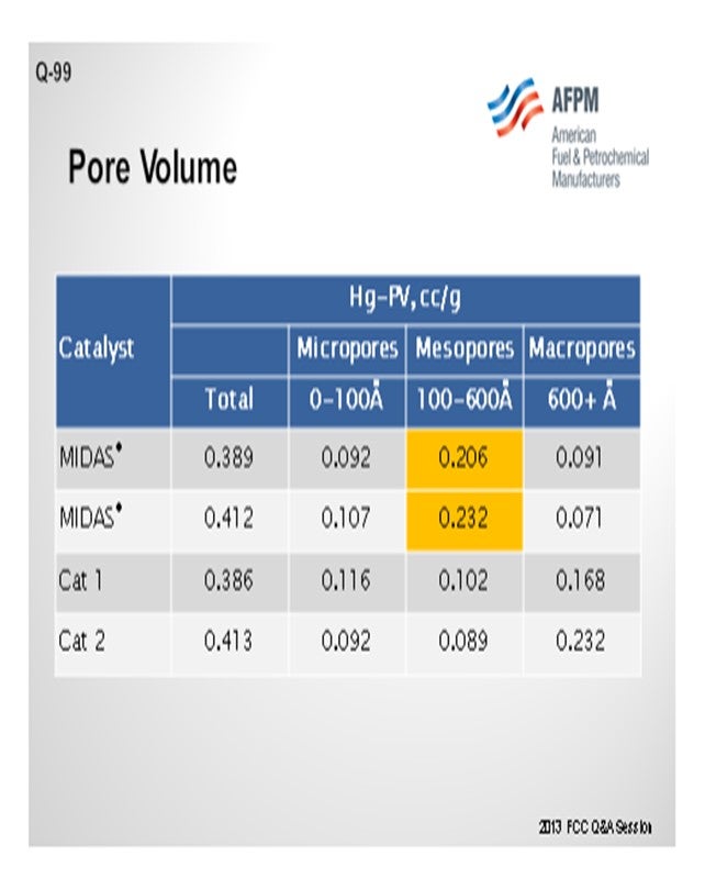
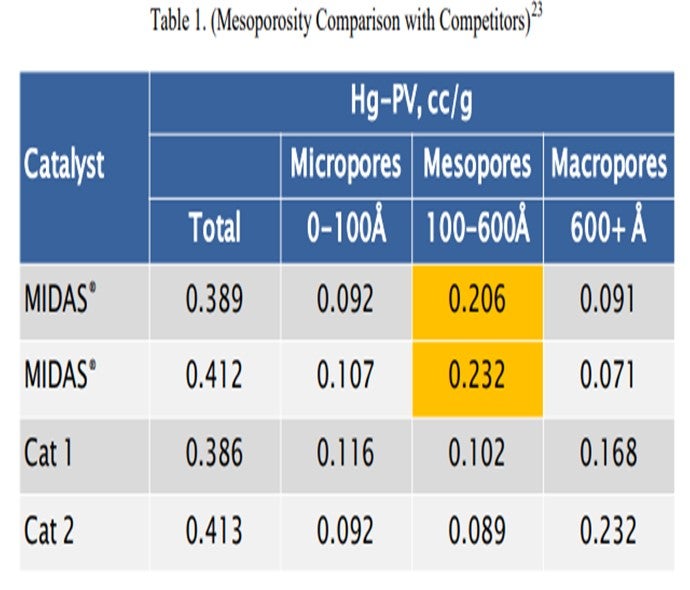
There are a lot of parts to this question, so I will respond to them independently. One of the catalyst design features that is important in any kind of feed, when you are going to get high iron and high calcium, is in the porosity. We talked a little before about how these contaminant metals tend to form these eutectics which can melt the surface of the catalyst and close off the pores. So having the right pore size distribution and mesoporosity in your catalyst is tremendously important. It is also really critical to look at the pore size distribution, not just the total pore volume; because in certain instances, you can have pore volume that measures consistently from catalyst to catalyst despite the difference in the pore size distribution. So I am sure all of the catalyst vendors will agree that the pore size distribution is a tremendously important piece of this puzzle.
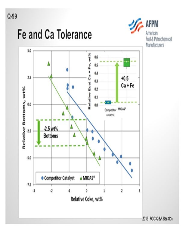
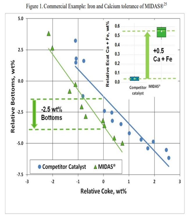
This slide shows an example of a commercial unit into which Grace put a MIDAS® catalyst. As I mentioned before, MIDAS® is a catalyst with which we take great care to optimize the pore volume and mesoporosity of the catalyst system. This particular unit ran relatively high iron plus calcium; and by putting higher mesoporosity into the system, we were able to help with the bottoms yield.
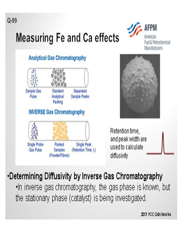
The question also asked about lab procedures we have found that simulate iron and calcium tolerance. Actual impregnation of iron and calcium on a fresh catalyst for lab deactivation is relatively difficult to accomplish. It is an ongoing area of research at Grace, but it is not one where we have found that the surface changes that happen to the FCC catalyst are easy to simulate in the lab. However, we do have a good test for actually measuring e-cat diffusivity. That test involves inverse gas chromatography where you take a gas chromatograph tube, pack it with FCC catalysts, and run a spike of a probe gas into it. If the FCC catalyst has a lot of diffusivity inherent in it, the probe gas will diffuse into and out of the catalyst sample that is in the chromatograph tube. It takes longer for the probe gas to come through in a more drawn-out profile on the other end, so you can measure the actual porosity of the catalyst sample quite well.
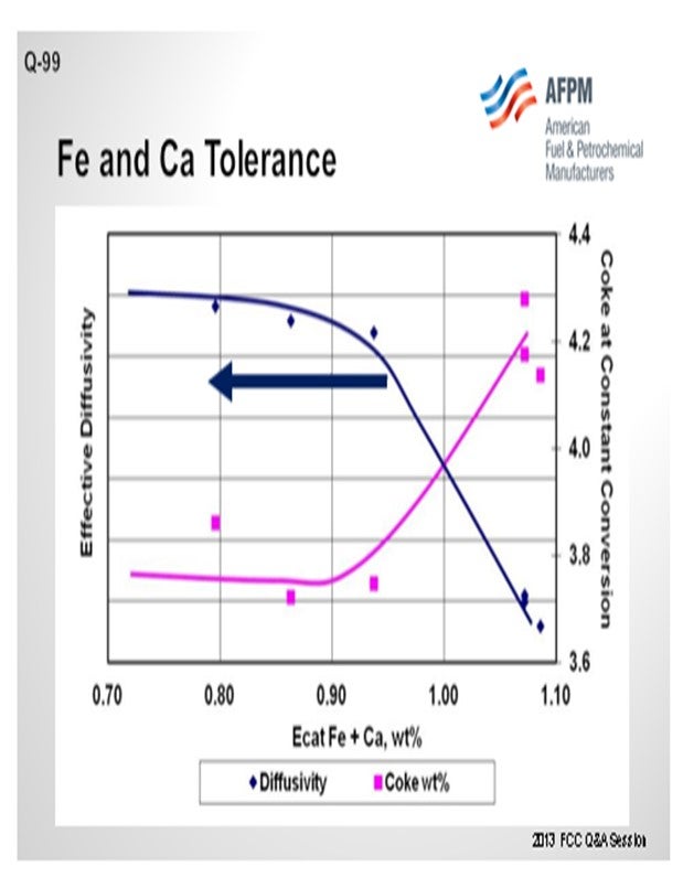
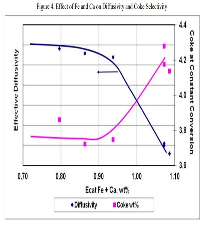
The next slide displays an example of the data from that type of testing and is representative of what we see across most samples. The blue line represents the effective diffusivity of the catalyst. As you pile on iron plus calcium, the diffusivity does not really change much until you fall off a cliff. In this case, that cliff happens at about 0.95 wt% iron. At that point, the bottoms yield, and the coke yield increase significantly. The detrimental effects of the contamination will be readily apparent in the unit at this point, and you will be able to observe the formation of the iron nodules on the catalyst particles as well. The actual level at where this rapid increase happens is going to vary greatly depending on the FCC catalyst.
It is very important to look at the amount of contaminant iron and contaminant calcium that you have on your FCC catalyst because all FCC catalysts, as well as the raw materials, have some base level of iron and calcium. To say that a catalyst will see this happen at 0.7 or 0.8 wt% iron is not really representative. You need to look at the delta amount of contaminant iron and contaminant calcium you are piling onto the catalyst. Grace certainly has experience with FCC catalysts running 0.6 to 0.7 wt% of contaminant iron plus calcium, which would equate to about 1.1 to 1.2 wt% of total iron plus calcium on the e-cat, while still maintaining reasonable bottoms conversion with a catalyst with properly designed mesopores and mesoporosity.
KEN BRUNO (Albemarle Corporation)
We agree with the comment Jeff made that pore size distribution is important, but we take it one step further. We believe that it is not only the internal pore size distribution, but it is also about the diffusivity of your surface. Again, when we wrap all that together and look at the accessibility, particularly with iron and calcium, we get a lot of deposits on the surface. With these deposits, you plug the surface, create an outer shell, and really decrease the diffusion character of the surface. We can capture that by measuring the accessibility. The key to overcoming that is, again, a good catalyst with high accessibility.
BART de GRAAF (Johnson Matthey INTERCAT, Inc.)
This question, like the previous one, shows that shale oil offers a lot of challenges, one of which can be octane. For the past 10 years, various suppliers have offered octane-selective additives that do not increase LPG. Butylenes can be an issue; and butylene-selective additives have been available for many years. Like Ken and Jeff said, various suppliers now offer catalysts with this selectivity in their base catalyst.
At Johnson Matthey, we spent a lot of time studying the effects of iron and calcium on the base catalyst. How does iron poisoning occur? We have one result we would like to share with you. One of the standard methods used to counter iron poisoning is adding e-cat next to the base catalyst. You are adding a lot of extra material to capture the iron and the calcium. You hope that in the end, by adding sufficient extra material, you will get just under the limit (of iron) that will seal off all of your catalyst pores. When you examine the catalyst or e-cats of a unit that has an iron poisoning problem and add e-cat that already contains a high iron content, you can see that the iron present on the base catalyst is slightly higher than you expected. Also, the iron present on the added e-cat is lower than anticipated from iron from the feed. This result suggests that although it was previously assumed that when you have an iron poisoned catalyst, nothing can be done to cure it, a minor amount of iron is mobile and can transfer by particle-to-particle interaction.
ROBERT “BOB” LUDOLPH [Shell Global Solutions (US) Inc.]
Question 29 of the 2006 NPRA Cat Cracking Seminar covered calcium effects on catalyst and equipment quite well. Catalyst porosity can have a profound effect on calcium and iron tolerance, “soaking up” nearly twice the base level if you significantly increase your porosity. But the pace at which the iron or calcium builds on catalyst in your unit is also a player. If you maintain good control of the feed blend, then higher levels can be achieved; if feed calcium and iron swings widely, then your unit tolerance will be much lower.
JOE McLEAN (BASF Corporation)
There has been a lot of talk about iron, aside from tight oil, for many years. The connection between iron and tight oil is just a new wrinkle on an old theme. An additional effect is that iron does act as a CO promoter. In a full-burn unit, you probably do not care. But if you are in a partial-burn unit, the CO promotion effect can really play havoc with the heat balance; so that is another effect of iron that you have to take into account.
We talked about iron and calcium, but iron poisoning is much worse when calcium is present than when it is not. That just goes back to the composition needed to form these eutectics. On the surface, it is silica. To make a glass, you need the silica source; you need the alkali source; you need the metal. The three of them together can then play a role. Of course, all FCC catalysts have silica if they have zeolite in them. That is where it originates. So they are worse together than either one is by itself. If you are in partial-burn and trying to control the CO level, you will have more difficulty in a high iron poisoning system.
PAUL DIDDAMS (Johnson Matthey INTERCAT, Inc.)
An additional effect of iron is that at high enough levels, it may behave as a reverse SOx additive. Fresh iron coming into the unit with the feed is able to pick up H2S (hydrogen sulfide) in the riser and transport it to the regenerator where it is converted to SOx.
UNIDENTIFIED SPEAKER
To expand on what Bob said, one final effect of iron is that iron action, especially when just fresh, is at the hydrogenation catalyst. So you may see coke and other things happening with an increase in FCC dry gas. If you have a unit that is in some way limited on coke-bearing capacity, you may get some negative effects that are interpreted as catalyst poisoning; but in reality, it is related more to making additional coke from the fresh iron that you are bringing into the unit.
ROBERTSON (AFPM)
Before we get to Question 100, I want to recognize and thank Yvette Brooks. She works for AFPM. She sits up here for all four of the Q&A sessions and keeps the program flowing in order so that we can get the transcripts out quicker. Over the last three years, these transcripts have come out months earlier than in the past as a result of the work Yvette does up here to stay organized. So Yvette, thank you very much. I also want to recognize Wendy Hefter with DWH Office Services. She is not here today; however, she takes the materials that Yvette prepares onsite and then painstakingly produces the final transcripts that are distributed in March.
GIM (Technip Stone & Webster)
My understanding is, with iron poisoning, that there is a distinction between organic and inorganic iron. It is the organic portion that causes the iron poisoning. Does anyone actually measure those two compounds differently or just total iron?
GEORGE YALURIS (Albemarle Corporation)
I am not familiar with a technique for measuring how much of the feed iron is molecular (organometallic), colloidal, or particulate. Usually, you can tell by examining the particles of the equilibrium catalyst after the iron has deposited on them. Different types of iron create different morphological features on the particle, so you can make conclusions from appearance differences when imaging the unit e-cat using the SEM/EDX technique. There is no clear size separation between the various types of iron. There is a continuum of iron that forms from molecular (organometallic)-type iron to colloidal and finely dispersed, all the way to particles which are up to catalyze size, are rich in iron, and come with the feed. The amount of destruction of the FCC catalyst iron will cause will depend on the size of iron species in the feed. The smaller, closer to molecular size the iron species are, the more destructive they will be the larger, the less likely they will cause any problems. I have seen units that have had very high iron; but because the iron was from large particulates, it had no effect on the catalyst performance.
JEFF KOEBEL (Grace Catalysts Technologies)
Catalyst design can be optimized to resist the effects of contaminant iron and calcium. High alumina catalysts, especially catalysts with alumina-based binders and matrices such as GRACE’s MIDAS® technology, are best suited to process iron- and calcium-containing feeds because they are more resistant to the formation of low-melting-point phases that destroy the surface pore structure.20 Optimum distribution of mesoporosity also plays a role in maintaining performance because diffusion to active sites remains unhindered, despite high-contaminant metals. Consider that while two catalysts may have similar total pore volume, their mesoporosity can vary greatly.21 MIDAS® catalyst was designed to maximize the abundance of mesopores or pores in the 100 Å to 600 Å size range. Table 1 shows the mercury pore size distribution of MIDAS® catalyst compared to competitive bottoms cracking catalysts.22 As can be seen here, even with similar total pore volume, MIDAS® technology has nearly twice the amount of pore volume in the 100 Å to 600 Å mesopore range compared to the competitive samples. This abundance of mesoporosity enables MIDAS® catalysts to more readily resist the poisoning effect of contaminant Fe and Ca.
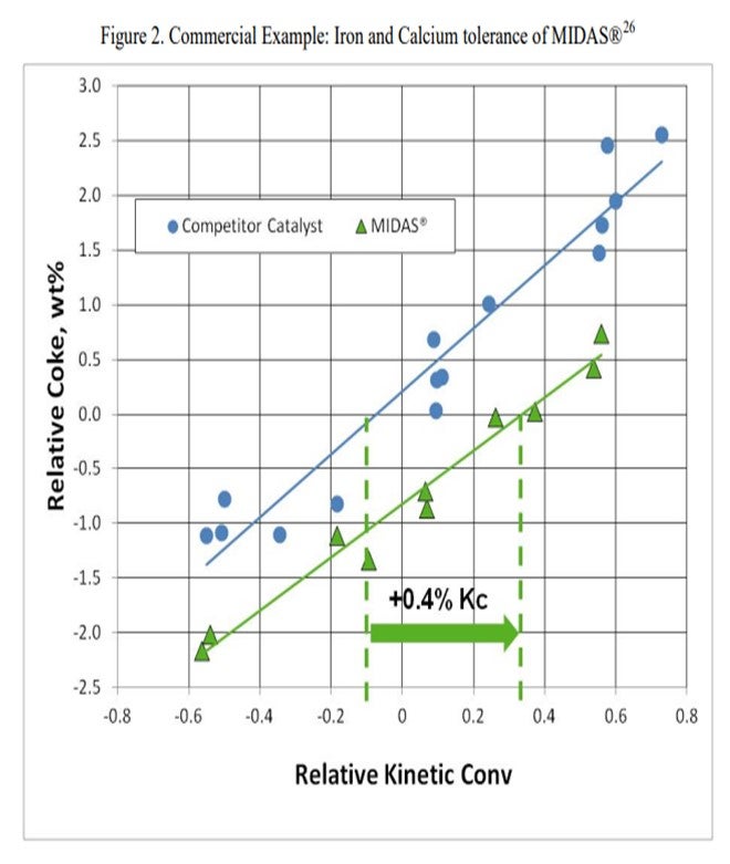
The resistance of MIDAS® to iron and calcium poisoning has been demonstrated in many commercial applications. Figure 1 and Figure 2 present the data from one such example. A refinery was processing a feedstock high in iron and calcium. Over time, the unit exhibited the symptoms of iron poisoning. Iron nodules built up on the catalyst surface and conversion, and bottoms cracking began to suffer. The catalyst was switched from a competitive catalyst to MIDAS®. Upon switching, activity, bottoms cracking, and coke selectivity improved despite the higher metal's levels.
To address the part of the question regarding lab simulation of Fe poisoning, it is not currently possible to simulate the full effect of Fe and Ca poisoning on FCC catalyst performance in laboratory scale deactivation. Iron poisoning causes changes in catalyst morphology and texture in the commercial unit with the formation of nodules on the surface. These nodules have been difficult to replicate in the lab. Laboratory simulation of iron deactivation is an area of ongoing research at Grace.
Impregnation with calcium can cause ion exchange in the zeolite, resulting in undesired changes in the catalyst unit cell size. Grace is working with spray coating techniques to better simulate calcium deposition.
Grace does have an available laboratory test method that can measure the effects of Fe and Ca poisoning. The diffusivity test can confirm adequate diffusion into and out of the pores of a sample of FCC e-cat. The diffusivity test is a proprietary method using inverse gas chromatography, which is depicted in Figure 3. A section of chromatography tube is packed with the e-cat sample. A pulse of a probe gas is shot into the tube, and the rate that the probe molecules pass through is related to the diffusivity. The probe gas molecules will go into the pores of the e-cat, so the rate they pass through will be slower and the diffusivity number will be high. For e-cat with plugged pores due to Fe or Ca contamination, the probe molecules will flow right through, and the diffusivity number will be lower.
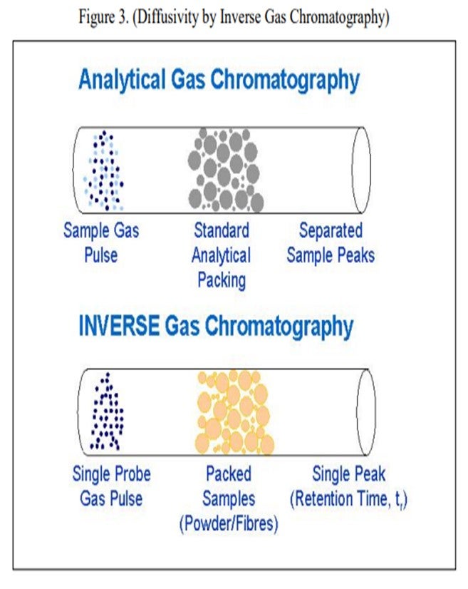
Figure 4 is an example illustrating the impact of equilibrium iron plus calcium on diffusivity. A drop in diffusivity results in an increase in coke at constant conversion. As these contaminants build up on the surface as rings, coke selectivity is lost due to mass transfer limitations, leading to higher rate of secondary reactions, e.g., coke.
'
The ability of a FCC catalyst formulation to tolerate Fe and Ca poisoning will vary greatly depending on the catalyst chemical makeup and the inherent porosity of the fresh catalyst. Grace has experience with units operating successfully with e-cat Fe in the range of 0.5 to over 1 wt%. A good general rule of thumb is that performance can begin to suffer with as little as 0.2 wt% incremental Fe if the catalyst is particularly prone to Fe poisoning.
PAUL FEARNSIDE (Nalco Champion Energy Services)
Increased iron (Fe) and calcium (Ca) removal can sometimes be accomplished across the desalters by carefully acidizing the desalter washwater. The acidizing essentially increases the solubility of both the Fe and Ca into the washwater for the increased removal.
CHRIS CLAESEN (Nalco Champion Energy Services)
If the largest part of the Fe is contained in the solids, the solids removal can be improved with a specific Nalco Champion solids wetting additive. Fe removal of over 90%, with desalted crude Fe levels below 0.5 ppm, has been achieved with this additive.
RAUL ARRIAGA and KEN BRUNO (Albemarle Corporation)
The critical catalyst feature for success with Fe and Ca poisoning is high accessibility, or in other words, a catalyst with superior internal and surface diffusional character. AMBER™ and UPGRADER™ were developed with high accessibility and are proven for tight oils. For additional insight, please see Albemarle’s answer to Question 98.
Regarding contaminant levels, with today’s technologies, an FCC catalyst can operate successfully with iron contents as high as 25,000 ppm and CaO (calcium oxide) as high as 28,000 ppm. Regarding laboratory procedures, Albemarle has developed a deactivation protocol to simulate the impact of high amounts of iron and calcium on a catalyst. The method is called CD-ALFA (Cyclic Deactivation with Accessibility Loss by Fe and Ca Addition) and was developed to simulate the effect of metal contaminants on accessibility. If a catalyst is not evaluated at its actual equilibrated accessibility, then the yields from performance testing are usually misleading. In nearly all cases, traditional deactivation methods, including cyclic deactivation and Mitchell/CPS, result in an Albemarle Accessibility Index (AAI) not reflective of its true value.
Year
2013
Process
Question 43: What are your best practices when shipping ecat, fines, feed, and slurry to suppliers for testing? Please also comment on some best practices for sampling equilibrium catalyst.
TODD HOCHHEISER (Johnson Matthey)
When shipping ecat or fines, an appropriate sample container should be used. Catalyst suppliers will typically provide refiners with sample containers if needed. Catalyst shipping containers should be made of plastic or metal. Glass containers are not recommended due to potential breakage but can be used with appropriate packaging. A screw top lid is preferred over a snap on lid sometimes found on metal containers. Prying opening a snap on lid can result in personnel dust exposure. Catalyst samples should not be shipped in plastic sandwich bags or other containers not designed for catalyst service.
JM has found that metal sample containers with a screw top lid are best when shipping low vapor pressure hydrocarbon samples. A best practice is to place the sample container in a plastic bag containing adsorbent pads. These pads should minimize the chance of hydrocarbons leaking out of the box if the sample container leaks.
For hazardous catalyst and hydrocarbon samples, a GHS complaint label must be placed on the sample container. The safety data sheet must also be included with the shipment. Most catalyst suppliers prefer for a safety data sheet to be included even if the sample isn’t considered hazardous. Other regulations and requirements may apply especially for sample shipments between countries.
Common sense precautions are also recommended. Some examples are shipping only the quantity of sample that is required, packaging in strong boxes, and using labels with high quality adhesive. Our lab has received sample boxes containing multiple ecat samples and multiple labels that are no longer attached to the sample containers. Clearly identifying the date of the ecat samples is critical for unit monitoring.
For any sample that is shipped, it is recommended that a company representative certified under DOT or applicable regulations be involved in the packaging and shipping process. Carriers also have specific requirements for shipping hazardous material.
KEN BRYDEN AND LUIS BOUGRAT (W. R. Grace & Co.)
For all samples, it is important to provide a safety data sheet (SDS) when shipping the sample and to follow appropriate Department of Transportation (DOT) and International Air Transport Association (IATA) rules when packaging and sending the sample. Samples should not be sent by U.S. Mail or any service that transfers to U.S. Mail. Based on our experience receiving and testing thousands of customers Ecat and hydrocarbon samples each year, Grace has the following suggestions on best shipping practices.
Ecat and Fines Samples
For Equilibrium catalyst (Ecat) and fines samples, we have found that for routine testing a 500 mL screw top plastic container is an ideal size. Grace provides complimentary Ecat Express containers for this purpose. Screw-top metal containers are another packaging option for Ecat. Glass containers are unsuitable for Ecat since they tend to break in shipment. Containers with paint can lids are unsuitable since the lids tend to come off during shipment and spill catalyst. Bags are also unsuitable containers since they tend to leak. For any container, do not put any tag, string or wire between the cap and the container lid since they will compromise the seal and cause leaking. For large quantities of Ecat, we have found that five-gallon (or 20 liter) plastic screw top buckets are good containers.
For Ecat and fines samples, proper labeling is important in making sure the desired tests are done and reported. At a minimum, samples should be labeled with the following information:
-
Refinery or company name.
-
Refinery location. For example, city and state.
-
Unit Name: Especially important if there is more than one FCC unit at the refinery location.
-
Sample Date: The date that the sample was collected.
-
Sample ID: (Optional) A sample number or name, for your reference.
-
Sample Type: for example, Ecat, fines, purchased Ecat, non-routine, etc.
As part of the complimentary Ecat Express kits, Grace provides container labels that already have the refinery name and unit written and barcoded on the label.
Feed and Oil Slurry Samples
For routine analytical testing to measure the properties of feed or oil slurry samples, a 16-ounce (or 500 mL) sample size is preferred. In shipping hazardous materials, proper packaging and labeling is essential to ensure compliance with the appropriate regulations. This will prevent fines from the carrier and delays in your shipment. In addition, poorly packaged samples can leak, which results in the sample being compromised and thus unsuitable for analysis. There are many good packaging systems available from suppliers that may be chosen to meet the packaging requirements of IATA and CFR49. Which system to use has to be determined by each individual shipper for their samples. The most common system that we see customers use is a 4GV shipper where the hydrocarbon sample is packaged in a metal can, which is then placed inside a plastic bag with an absorbent sleeve. The entire assembly is then placed in a certified cardboard box. It is important to make sure that the lid is screwed on securely. We occasionally receive leaking samples where the container lid vibrated loose in shipment. In preparing containers, make sure tags and wires from labels are not in the thread area of a cap. A string or wire from a label tag put into the sample container, with the cap sealed over it, will act as a wick. This will always cause leaking. Container types that we have noted problems within the past are a) paint cans- the lids often pop off during shipment, and b) glass bottles- they have a tendency to break during shipment.
As with Ecat samples, labeling of feed and slurry oil samples is important. The container should be labeled with the material identity and the appropriate Global Harmonized System (GHS) hazard symbols. Additionally, the sample should be labeled with the following information:
-
Refinery or company name
-
Refinery location: for example, city and state
-
Unit Name: especially important if there is more than one FCC unit at the location
-
Sample Date: the date that the sample was collected
-
Sample ID: (Optional) a sample number or name, for your reference
-
Sample Type: for example, feed, oil slurry, etc.
Process Ecat Sampling
Routine and representative sampling of the circulating Ecat inventory represents a critical part of FCC performance monitoring and optimization. Samples of the circulating inventory should be collected from a fluidized and accessible section of the unit to enable representative sampling of the catalyst system. From a safety standpoint, regenerated catalyst represents an inherently safer sampling source than spent catalyst due to the lack of entrained hydrocarbons and the lower coke concentration along the surface of the catalyst. However, the process temperatures associated with regenerated catalyst are significantly higher than those of spent catalyst and should be mitigated accordingly.
The regenerated catalyst standpipe represents the most common sampling location due to the continuous catalyst flow and accessibility associated with this standpipe. Although the flowing catalyst is well fluidized within this type of standpipe, it is important to properly fluidize the sampling manifold as well when obtaining a catalyst sample. Plant or instrument air are the most common fluidization media for regenerated catalyst sampling stations, which can also be equipped with steam connections to serve as blast points for line plugging troubleshooting. An air or steam purge into the process should be maintained at all times across the standpipe sampling nozzle to prevent catalyst ingress and nozzle plugging. The fluidization medium should correspond to a reliably dry source to prevent potential catalyst agglomeration issues throughout long-term operation. The sampling outlet nozzle should be purged prior to lining up the sampling line to the process to ensure that the manifold is clear of fouling and to confirm that the sample fluidization medium is available and properly dry. The key considerations and best practices for the Ecat sampling process, among others, are as follow:
-
Field personnel should be equipped with all necessary PPE prior to collecting the Ecat sample. Contact your catalyst vendor if any additional feedback or specific PPE guidelines are required.
-
Any potential impacts on instrument readings or safety interlocks by the Ecat sampling process should be thoroughly identified. Ecat sampling activities should be communicated to the board operators prior to starting the sampling process to help ensure that instrument and safety interlock functions are not compromised while sampling.
-
Ensure that the sampling container or recipient is adequately rated for the normal process temperatures associated with the circulating Ecat inventory. The sample containers used for shipping are not typically rated for these elevated temperatures. Metallic containers are typically required to accommodate Ecat sampling.
-
The sampling valve and the sampling outlet nozzle configuration should, ideally, enable sample collection without exposing field personnel to catalyst and entrained flue gas at the high process temperatures. A remote point where the operator can operate a HIC (Hand Indicate Controller) valve to take the sample in line of sight of the sample station but a safe distance away is practiced by several refiners. The sampling recipient can be attached to a long metallic or high-temperature-resistant handle to help mitigate personnel exposure to high temperatures throughout the sampling procedure.
-
Sufficient sample flow should be established to enable collection of a representative Ecat sample. Insufficient purging of the sampling manifold with the flowing Ecat can lead to non-representative or compromised results due to the presence of stagnant Ecat from previous sampling rounds, or other similar contamination sources. Collection of a slip stream during continuous Ecat flow through the sampling line tends to yield a more representative sample than collecting a vial sample from a drum or (large container) of Ecat sample inventory.
-
Excessive superficial velocities through the sampling manifold should be prevented while sampling to help mitigate potential erosion and attrition issues. Excessive catalyst attrition through the sampling line can lead to false PSD profiles for the circulating catalyst inventory that can prompt unnecessary troubleshooting activities. Adequate velocities through the sampling nozzle also help reduce turbulence and dust as the flowing Ecat reaches the sampling container, thus preserving as much of the fines content present in the circulating inventory as possible.
-
A pint of Ecat sample is usually sufficient volume to accommodate routine lab testing for process monitoring purposes. Excess Ecat sampling volume should be properly handled and discarded via spent catalyst drums or disposal lines routed to the spent catalyst hopper, if available.
-
Ecat samples should be allowed to properly cool before filling the corresponding shipping containers. Windy or wet environments should be avoided for the cooling period to avoid altering the physical properties of the Ecat sample.
The guidelines and best practices previously referenced should be followed when shipping the Ecat sample containers. Board operators, unit engineers and other supporting staff for the FCC complex should visually inspect Ecat samples before the sample is shipped to the catalyst vendor. Visual inspection can help qualitatively gauge the health of the circulating catalyst inventory – especially with respect to coke on regenerated catalyst (CRC), drastic PSD shifts, and/or potential Fe poisoning contamination – well before the corresponding lab results become available.
Year
2019
Process