Question 50: What are the technology evaluations and engineering studies required for revamping a diesel hydrotreating unit to substantially increase throughput?
LIOLIOS (DuPont Clean Technologies)
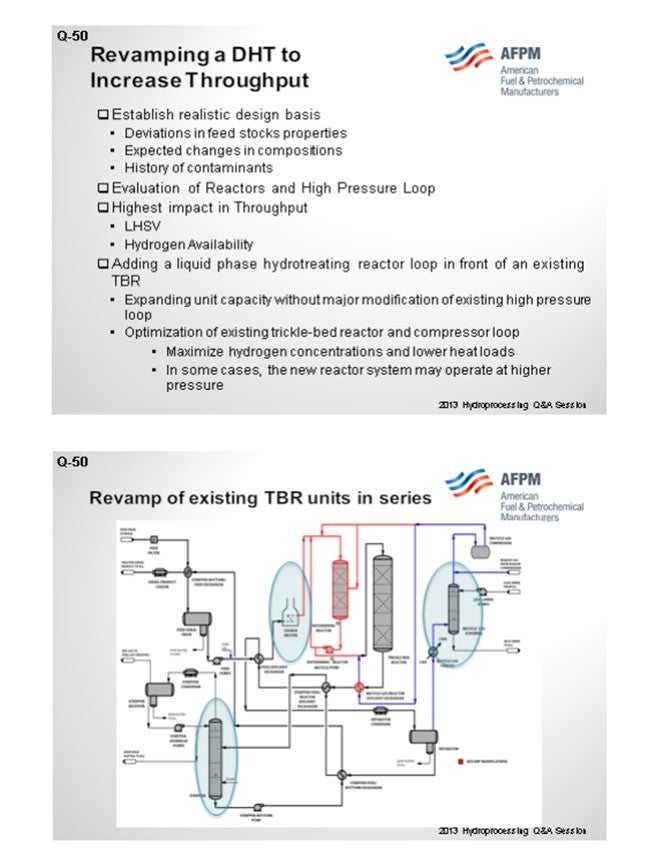
In any major revamp of throughput for a DHT (distillate hydrotreater), establishing a realistic design basis and engineering certainly never really exists. The idea is to look not just to the point but at deviations and feedstock properties, expected changes in compositions, and past history of contaminants. Evaluation of the reactors in the high-pressure loop is where we tend to do a concentrated effort because there is a lot of give-and-take on cycle life versus temperatures to accomplish the objectives of a particular throughput increase in the revamp. Obviously, we have to look at liquid and space velocity, catalyst selection, and hydrogen availability.
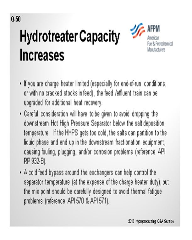
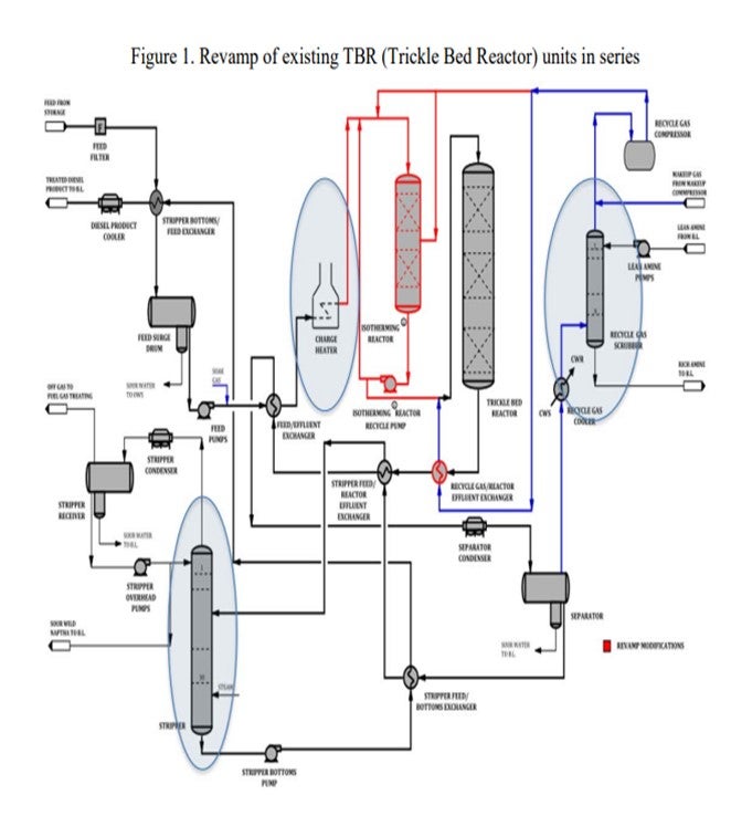
We have been successful revamping a couple of DHTs by adding liquid hydrotreating reactors, either adding or revamping series reactors by putting a liquid reactor in front. In one case, converting a trickle bed to a liquid reactor had some substantial advantages without significant changes in the stripping or fractionation areas. It is a great way to get a revamp. It not only increased capacity; but in some cases, you will be able to get to the lower sulfur in the product.
SHARPE (Flint Hills Resources, LP)
If your charge feeds are limited, especially for end-of-run conditions or with no cracked stocks in the feed, the feed effluent train can be upgraded for additional heat recovery. You have to give careful consideration to doing that to avoid dropping the downstream hot high-pressure separator below the salt deposition temperature. If the hot high-pressure separator gets too cold, the salts can partition to the liquid phase and end up in your downstream fractionation equipment causing fouling, plugging, or corrosion issues. I have referenced API 932B for you to review the guidelines. If your hot high-pressure separator is too cold, you can put a cold feed bypass around the exchangers to help control the temperature. Obviously, it will not work if your charge feed is limited. In our Eagle Ford crude cases, we are running cold on the reactor circuit, in general, and then putting a cold feed bypass, which will help control your hot high-pressure separator temperature. In that case, make sure you design your mixing point very carefully to avoid thermal fatigue issues. API 570 and 571 have some guidelines on proper design.
Other envelope issues to consider: Your waterwash systems need to be evaluated and revised to provide adequate washwater capability. Water removal capabilities of the upstream charge drum and downstream equipment need to be evaluated to avoid reliability issues associated with corrosion or potential product quality issues. On ULSD revamps, the feed cutpoint has to be a major bearing on your sulfur species and, therefore, treating requirement reactor sizes. If you are not changing out the reactor, catalyst life and run-length penalties must be assessed. Potential vibration issues in exchangers, piping, thermal wells, and quills need to be evaluated due to changing velocities and flow regimes.
The fractionation capabilities need to be evaluated and will be very unit-specific, depending on your required product specs and fractionator heater capabilities. One of the big considerations is hydrogen system management and optimization for an upgrade on rate in optimizing catalyst life management. You need to look at what maximum catalyst axial ∆Ts (temperature differentials) are allowable, which will depend on your bed outlet hydrogen partial pressure. You also must ensure that there is enough emergency reserve quench available for feedstock variations and unit perturbations and upsets. That is important, especially if you will be running more cracked stocks with your revamp. By the same token, quench valve capacity testing and availability are important for sizing basis. Hydrogen uptake for bed and hydrogen partial pressure limits of the bed outlets, both for catalyst light management and potential ∆P problems, needs to be evaluated. That is important from your emergency reserve quench as well.
R.E. “ED” PALMER (Wood Group Mustang, Inc.)
One of the biggest issues on a revamp is the mechanical design conditions of the entire reactor loop; because once you push capacity, the whole pressure outlet system goes up. The other point is really the upset pressure on the separator drum.
I want to make another comment. On any revamp study, we like to see a good set of operating data before we do a process simulation of the whole unit based on the data, including a really good reactor loop hydraulic profile to understand the real equipment and piping pressure drops versus the target pressure drops
JEFF JOHNS (Chevron Products Company)
I agree with a lot of the points that were shared. One of the most neglected considerations I have seen most recently has been the relief system. One of the easiest ways to get more feed through a hydroprocessing unit is to increase the size of letdown valves from the separator, but a lot of people forget to then evaluate the relief capacity downstream for a potential blow-through case. That omission has caused serious incidents within the industry.
GATES (Motiva Enterprises LLC)
I also want to add that as you are increasing unit charge rates, you are likely changing the operator response times to unit upset conditions. So, it is probably a good idea to take a quick look at the PHA (Process Hazard Analysis) and reevaluate to confirm that there were no sudden changes in operator responses to emergency conditions.
HELMY ANDRAWIS (WorleyParsons)
We get a chance to revamp quite a few hydrotreaters. Most of them are 30 to 40 years old, so certainly design pressure and temperatures on relief systems. For quite some time, we have seen many units pushed beyond their design limits and throughput.
I also want to make a comment about inspection reports. We take for granted that some of this equipment is good. We have had quite a few experiences where the inspection reports did not quite reflect the exact conditions of the units.
SHARPE (Flint Hills Resources, LP)
That is a very good point about the PSV (pressure safety valve) of a blow-through case. When reviewing a blow-through case, you need to look not just for liquid and hydrogen together, but also for hydrogen only. Frequently, a hydrogen-only blow-through case will set your downstream and relief valve pressure rating and sizing basis.
XIOMARA PRICE (GE Water & Process Technologies)
I agree with the waterwash revamp and making sure it is adequate because a little waterwash can be worse than no waterwash at all in your system. In addition, when revamping your unit, make sure that the filters are in front of the unit so that:
1) the throughput you have is continuous,
2) you are not fouling the system, and
3) you are able to maximize your throughput.
One other area that tends to get neglected is that you have not designed the unit to have problems; but when you do, to have the right-sized valves to put in the chemistries that you may need to address the problems. It is quite important to think about injection points when designing your systems.
JOHN PRICE (WorleyParsons)
Another consideration that is often overlooked is the assessment of cooling capabilities with revamps. Reviewing the cooling tower’s designed hydraulic and cooling capability and/or the air fin cooler’s design as compared with the current operating performance is typically neglected in the early stages of an engineering effort for expanding hydrotreating units.
GLENN LIOLIOS (DuPont Clean Technologies)
The first step in any revamp analysis is to establish a realistic design basis with careful consideration to sensitivity of changes in feed stream properties, composition, and contaminants. We generally start by evaluating the reactors and the high-pressure loop as these two systems are typically the major limitation. For most systems, the reactor space velocity and hydrogen availability limit high throughput increase.
Considering liquid-phase hydrotreating technology can provide a unique solution. Adding a reaction loop upstream of the existing trickle bed can provide great capacity increase capabilities. This allows for expanding the unit capacity without having to modify the existing high-pressure loop as the hydrogen is carried by a liquid recycle. By moving part of the hydroprocessing load to the new reactor system, the trickle bed reactor and compressor loop can be optimized to maximize high hydrogen concentrations and lower heat loads. In some cases, it is possible to design the new reactor system to operate at higher pressure, thereby allowing additional optimization of the new purposed trickle bed reactor.
If the existing trickle bed unit has two reactors in series, revamping the first reactor to liquid phase technology has also shown substantial capacity increases with much lower capital investment than other options.
As with all revamp studies, the aforementioned work is evaluated several times to make sure that the capital optimization and operability meet the project threshold. There are always tradeoffs, and this re-evaluation is a critical step to maximize the benefits based on the constraints of the existing unit.
Next, we evaluate the heat integration and the fractionation equipment. Finally, we evaluate the product rundown system and safety valves. A thorough evaluation will also include a review and potential upgrade of existing reactor internals to state-of-the-art internals.
Other items that may need to be considered are amine absorber, including amine type; catalyst options for higher activity; and, feed section, including charge heater.
JESUS PEREZ (Alfa Laval Inc.)
A key study to perform is how to increase heat recovery without adding pressure drop on the diesel hydrotreater unit. Significant fuel savings in the fired heater can be achieved by minimizing the HAT (hot approach temperature), which is also known as ROT-HIT (reactor outlet temperature–heater inlet temperature) of the feed-effluent heat exchanger. The installation of a welded-plate heat exchanger can provide both higher heat recovery and lower pressure drop. Since the 1990s, Alfa Laval Packinox has commissioned 22 welded-plate heat exchangers in distillate hydrotreating applications all over the world with one more unit being delivered next year. For additional information on the subject, we suggest that you refer to Alfa Laval Packinox’s response to Question 23 from the 2008 NPRA Q&A. This question was, “What is your experience with and acceptance of high efficiency plate exchangers in high-pressure hydrotreating service?”
HOWARD WU (Haldor Topsøe, Inc.)
1) Kinetics are used to determine if the existing reactor would have enough catalyst volume to meet the process objective for the higher throughput. If it does not, then one may need to add an additional reactor or accept shorter cycle lengths. Topsøe has done many ULSD, CGO, and coker naphtha unit revamps. We have found that adding additional reactor volume is quite feasible and economical for refiners and allows the unit to operate at a lower gas-to-oil (G/O) ratio, thereby avoiding investment in a larger compressor. Topsøe offers Reactor Design Packages (RDPs) which are geared for the addition of reactors for refiners whose main bottlenecks were in catalyst volume.
2) Engineering is utilized to determine if existing equipment can handle the higher flow. With a higher throughput, the pressure drop will be higher in the system and the existing compressors, heaters, exchangers, vessels, towers, and pumps may no longer be adequate. Topsøe will provide refiners with a Revamp Process Design Package (Revamp PDP) or a Revamp Engineering Design Package (Revamp EDP) to simulate the whole unit and identify limitations of equipment. It includes development of new PFD with hydraulic analysis, heat integration, and process evaluation of vessels, rotating equipment, and towers.
Year
2013
Process
Question 51: For hydroprocessing reactor modifications that involve the addition or removal of distribution trays and flexible thermocouples, what is your Best Practice for welding support rings or support lugs on a reactor wall? What is your Best Practice for removal of these items when they are no longer required?
SIVADASAN (UOP LLC, A Honeywell Company)
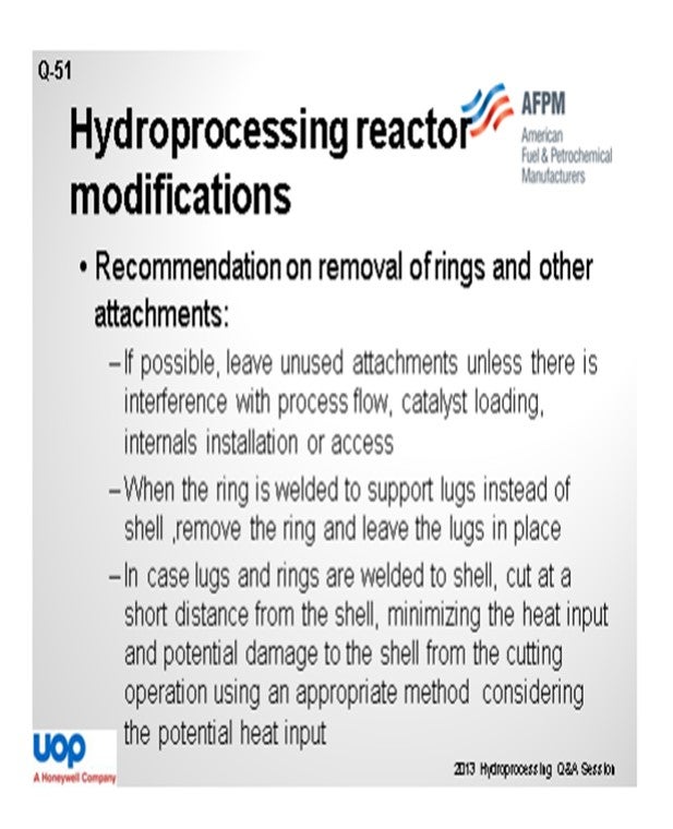
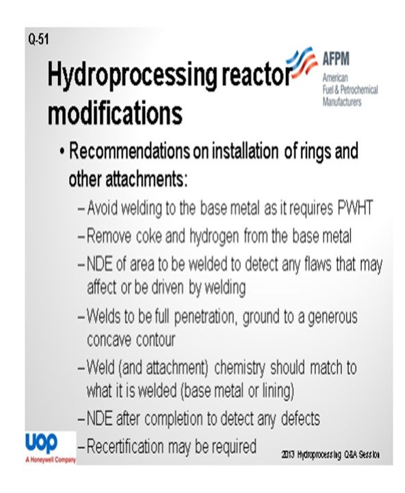
When you are trying to remove the attachments from the reactor, do not touch them unless it interferes with your process flow, catalyst loading, or internal installation or access. When the rings are welded to the support rigs, remove the rings and leave the lugs in its place. If both the lugs and the rings are welded into the shell, try to cut a short distance from the shell, using appropriate cutting methods, in order to minimize the heat input and potential damage to the shell from the cutting operation. When trying to install the attachment, avoid welding to the base metal; because once welded, a post-weld heat treatment may be required.
If you plan to go ahead with the cutting operation, do the removal of the coke and hydrogen from the base metal and do an NDE (non-destructive examination) of the area to be welded to detect any flaws that may be affected or ruined by welding. The weld needs to be full-penetration and ground to a generous concave contour. The weld-and-attachment chemistry should match what it is being welded to at the base metal. Once the welding has been done, do an NDE to detect any defects. Once the NDE is complete, a recertification based on the laws prevailing in that country may be required.
RAJESH SIVADSAN (UOP LLC, A Honeywell Company)
In hydroprocessing reactors, support rings are used to support internals like a tray or catalyst support grid. Support rings are fixed on the reactor ID (inner diameter) either by weld buildup to the base metal or forged as part of the shell course. The following recommendations apply to reactors made of low chrome base metal in hydrogen service:
Recommendations on Removal of Rings and Other Attachments
1. If possible, leave unused attachments in place. They should be removed if they will interfere with process flow, catalyst loading, internals installation, or access.
2. Where the ring is welded to support lugs but not to the shell, and when leaving everything in place is not possible but only the ring needs to be removed, then remove the ring and leave the lugs in place. In this case, cutting at or near the shell is not required. If cutting near the shell is necessary, the points in #3 (below) apply.
3. Cut lugs and rings welded to the shell a short distance from the shell (e.g., closest approach of the cut to the shell at least 10mm). The intent is to minimize heat input into the shell and minimize the potential for damage to the shell from the cutting operation. The cutting method should be chosen considering the potential heat input. A dehydrogenation heat treatment may be necessary before cutting, and NDE before and after cutting is advisable. If coke is present, it must all be removed. NDE before cutting may identify a defect (e.g., crack) that might be driven by the cutting operation, and NDE afterwards may identify a defect caused or enlarged by the cutting operation.
Recommendations on Installation of Rings and Other Attachments
1. Welds should be full-penetration, ground to a generous concave contour. Stainless steel rings should not be circumferentially welded. Weld (and attachment) chemistry should match to what it is welded (base metal or lining).
2. Welding to the base metal should be avoided. PWHT (post-weld heat treatment) of low chrome requires an elevated temperature [e.g., 690°C ± 15°C (1275°F ± 25°F)]
3. Removal of hydrogen from the base metal (dehydrogenation heat treatment) and removal of coke may be necessary.
4. NDE of the area to be welded to find any flaws that may affect or be driven by welding. If welding to lining, UT to confirm the lining is 100% bonded. For heavy loads, UT of the base metal may be necessary to ensure there are no laminations.
5. Weld the lining using a procedure that does not require PWHT of the base metal, i.e., the heat-affected zone does not penetrate the lining. This will require a mockup to confirm.
6. NDE should be conducted after completion of the attachment to detect any defects caused or driven during the attachment process.
7. A recertification of the reactors may be required.
KLAUS RISBJERG JARLKOV (Haldor Topsøe, Inc.)
Adding support rings or clips to a reactor shell depends on several factors:
• Existence or absence of weld overlay,
• Size of bracket/support ring, and/or
• Magnitude of the load size support and weld size.
If the reactor is provided with weld overlay, adding a support ring/support clip may be done using low heat input welding using a weld size, which will not affect the base material. The welding must be done by a certified stainless steel welder. If a strong weld is required, a larger weld can be applied by using several pass welds with sufficient cooling time in between the passes. The root pass should be touchable by hand before continuing with the next pass.
If the support ring/lug/bracket is heavily loaded and requires being fully welded to the base material, pre-heat treatment and post-weld heat treatment will be required in accordance with the code.
Carbon steel reactors will require both pre-heat treatment and post-weld heat treatment in accordance with the code.
Support rings/lugs made of stainless-steel material can be removed by grinding. Use caution not to damage the weld overlay. Sometimes it will be possible to weaken the weld beads on the brackets and thereafter remove it by knocking it from side to side until it breaks. For heavier brackets/support rings, gauging may be used. Leave at least 1/8" to the weld overlay and use a protection shield between the weld overlay and gauge. If the bracket is removed flush to the weld overlay, pre-treatment of the area is recommended.
Attachments that are welded to carbon steel or low alloy steel, pre-heating, and other heat treatments specified in the welding procedure shall also be applied in order to prevent cracking.
ROBERT TORGERSON and SYDNEY GARRETT (Gayesco International)
We find it extremely rare, during hydroprocessing reactor modification, that rings or support lugs are added to the reactor other than near the outlet collector on the final bed. It is much more common to use low profile support rods attached to the distribution tray for inlet points with only the end of thermocouple penetrating into the active catalyst to minimize interference. Outlet points utilize low profile supports coming up from the catalyst support beams directly aligned with the inlet point above. This prevents the necessity of welding to the reactor.
Additionally, it is possible to use any existing attachments in the reactor as part of the thermocouple support network. Supports for old pipewells or previous thermocouple installations are good examples. We have also had retrofits involving welding of supports to the wall; but given the ease of the vertical support rod installations, that practice has significantly decreased.
Year
2013
Process
Question 52: What is the configuration of thermocouples that can be used to effectively monitor radial temperature differences, and what is the acceptable radial temperature spread in hydrotreaters/hydrocrackers?
SIVADASAN (UOP LLC, A Honeywell Company)
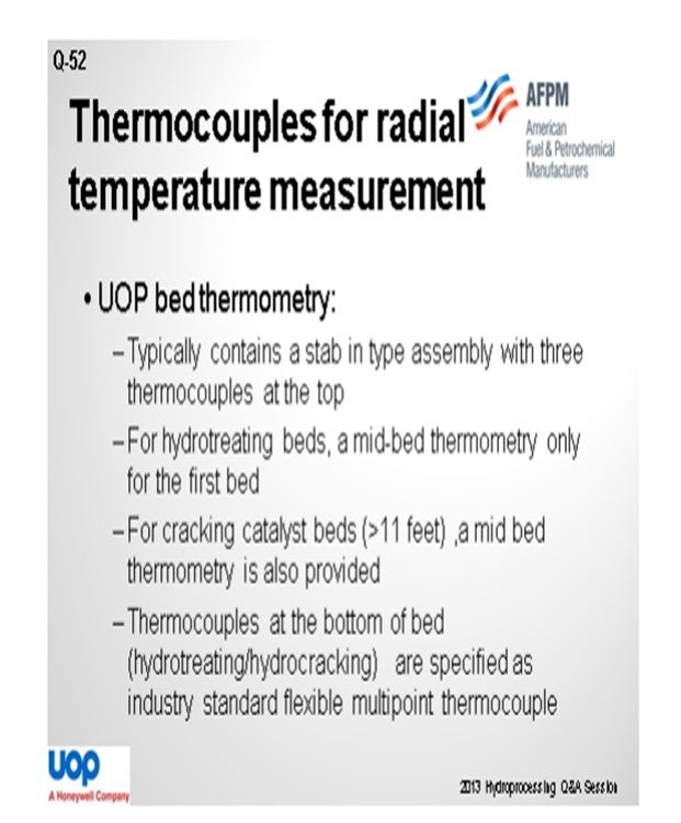
The UOP bed thermometry consists of a stab-in type of assembly with three thermocouples on top of the bed. Typically, a multipoint thermometer is provided in the case of the first bed of a hydrotreating unit and if the bed length is more than 11 feet for a hydrocracking bed. At the bottom of the catalyst bed, industry-standard flexible-type multipoint thermocouples are specified.
Radial temperature spread is the difference between the maximum and minimum temperature at the same elevation level. It is monitored at various levels in the reactor and is the primary indicator of flow distribution within the catalyst bed. Ideally, the thermocouple at the same level should register identical temperatures; but sometimes, less-than-perfect distribution of the reactants in the catalyst bed happens due to different factors.
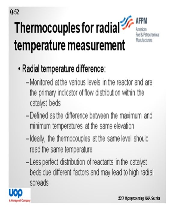
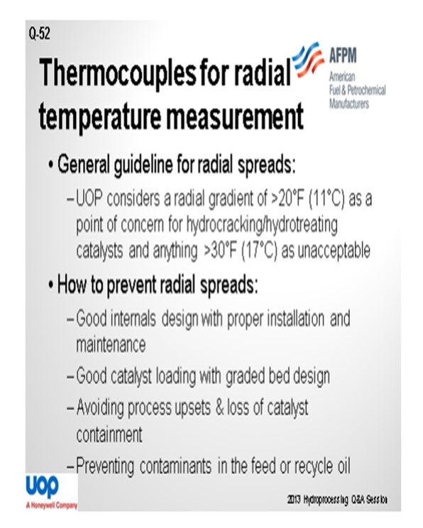
Our guideline is that a radial gradient higher than 20°F is considered a point of concern. It is not acceptable for it to be more than 30°F. So how can you prevent this radial spread? Try to have a well-designed internal with proper installation and maintenance and good catalyst loading with appropriate catalyst bed design. Also, avoid process upsets and loss of catalyst containment and prevent contaminants in the feed or recycle oil.
LIOLIOS (DuPont Clean Technologies)
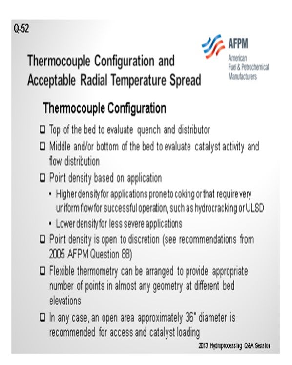
Configuration of thermocouples at the top of the bed are effective for evaluation of quench and distributor performance. When placed in the top, middle, and bottom of the bed, they are used to evaluate catalyst activity and flow distribution. Point density, of course, depends on the application. Higher density is required for systems prone to coking and which require a very uniform flow for successful operations, such as hydrocracking or ultra-low sulfur diesel. Lower density is also necessary for less severe applications. The 2005 AFPM Q&A transcript has a lot of valuable discussion on point density. A flexible thermometry can be arranged to provide the appropriate number of points in almost any geometry at different bed elevations. In any case, an open area of approximately 36 inches in diameter is recommended.
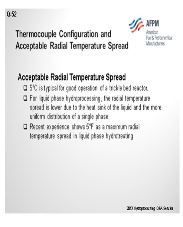
The acceptable radial temperature spread of 5°C is typical for good operation of the trickle bed. For a liquid-phase hydroprocessing reactor, the radial temperature spread is lower due to the heat sink of the recycled liquid. Typically, we experience about 5°F as a maximum radial temperature spread.
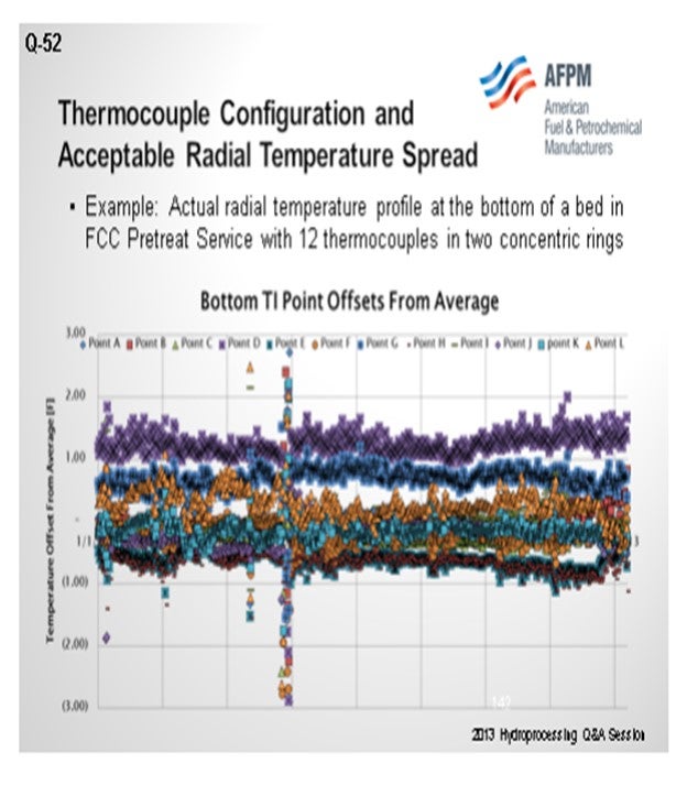
This graph shows an example of thermocouple configuration and acceptable radial temperature spread. It was derived from a liquid-full reactor with 12 thermocouples and two concentric rings and basically shows very uniform and comprehensive fuel temperature differences in the radial change in FCC pre-treat service.
VICHAILAK (Marathon Petroleum Corporation)
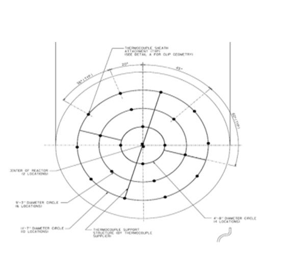
From the picture, you can see that we require 6” below the top, as well as 6” both at the bottoms and one-third of the bed and then two-thirds of the bed. These are the minimum readings per ring, which add up to nine readings. The radius of the ring has to be two-thirds of reactor radius. If you have high severity like in a hydrocracker, then you will have an additional four skin thermocouples at the bottom of each bed, too. Also, we add another ring at the very bottom and one more thermocouple in the middle of the reactors. The more you add thermocouples, the more information will be available to you.
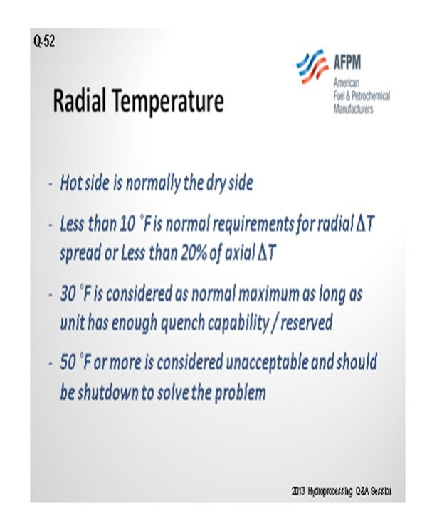
We have one reactor that did not have enough thermocouples. Once added in, we started seeing new information, and people were not able to sleep. A hot side is normally a dry side because liquid is a very good heat sink. If you have a dry side, then you see that the temperature will be higher. We normally require 10°F as it is considered normal radial ∆T. But if you do not have axial ∆T, you should not have radial ∆T; nor if you have 10°F or 20% of axial ∆T, whichever is lower. Thirty degrees is considered the normal maximum probably for as long as you have quench. For example, if you have a 60-foot catalyst bed and 30°F at the bottom, there is no way you will be able to quench as well; so that scenario can be considered severe. But if a temperature of greater than 50°F is not acceptable, we will shut down and replace the bed.
RAJESH SIVADSAN (UOP LLC, A Honeywell Company)
UOP bed thermometry typically contains a stab-in-type assembly with three thermocouples at the top.
For hydrotreating beds, mid-bed thermometry for the first bed is provided and not included in any other hydrotreating beds. Mid-bed thermometry is also provided for long cracking catalyst beds (greater than 11 feet).
The thermocouples at the bottom of bed are specified as industry standard flexible multipoint thermocouples. A typical Flexible Multipoint Sheathed Thermocouple arrangement is shown below.
The radial temperature profiles are monitored at the various levels in the reactor and are the primary indicator of flow distribution within the catalyst beds. Radial temperature differential is defined as the difference between the maximum and minimum temperatures at the same elevation. Ideally, the thermocouples at the same level should read the same temperature. The bulk of our experience suggests that most Unicracking™/Unionfining™ units do have fairly uniform radial temperature profiles in the catalyst beds. However, less than perfect distribution of reactants in the catalyst beds can occur. This may be due to improper catalyst loading, damage to reactor internals, or the reliance on older reactor designs with deep catalyst beds and older internals. Consequently, the temperature of the fluids leaving the catalyst bed at different locations can vary.
As a general guideline, a hydrocracking/hydrotreating catalyst radial gradient greater than 20°F (11°C) is considered by UOP to be high and a point of concern, while greater than 30°F (17°C) is considered unacceptable. In order to prevent radial gradients, there should be a perfect distribution of reactants in the catalyst beds, and this can be obtained by:
• Good internals design,
• Proper internals installation and maintenance,
• Good catalyst loading,
• Appropriate graded bed design, and
• Avoiding process upsets by
o Preventing contaminants in the feed or recycle oil (particulates including iron sulfide, organic iron) and
o Preventing loss of catalyst containment (usually leads to hot spots or temperature excursions and pressure drop buildup).
MONTRI VICHAILAK (Marathon Petroleum Corporation)
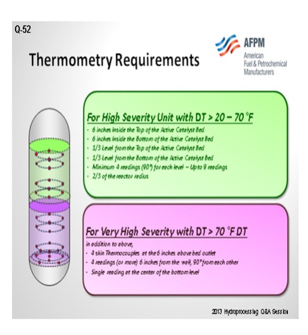
For a high severity unit with ∆T > 20°F to 70°F, the following parameters are recommended:
- 6 inches inside the top of the active catalyst bed,
- 6 inches inside the bottom of the active catalyst bed,
- 1/3 level from the top of the active catalyst bed,
- 1/3 level from the bottom of the active catalyst bed, and
- minimum 4 readings (90°) for each level: up to nine readings at 2/3 of the reactor radius
For a very high severity unit with ∆T > 70°F ∆T, in addition to the above suggestions, you will need:
- Four skin thermocouples at the 6 inches above bed outlet,
- Four readings (or more) 6 inches from the wall, 90° from each other, and
- A single reading at the center of the bottom level.
Flow maldistribution can be detected by observing the radial temperature differences. The hot side is almost always the dry side. We prefer to see any radial ∆T is less than 10°F or at most 20% of axial ∆T. Radial ∆T of 30°F is considered as normal maximum as long as unit has quench capability or reserved. Radial ∆T of 50°F or more is considered unacceptable and should be shutdown to solve the problem.
GLENN LIOLIOS (DuPont Clean Technologies)
Prior responses to this question [from the 2005 NPRA Q&A by Krause (Albemarle Corporation), McGrath (Foster Wheeler USA Corporation), and Spearman (Barnes and Click)] give good recommendations for the thermometry layout.
Thermocouples are useful in determining performance of the quench and distributor at the top of the bed and catalyst activity and flow distribution at the middle and/or bottom of the bed. Radial deviations can help troubleshoot issues inside the reactor that can influence the operation of the unit.
Using flexible thermocouples, radial arrangements in different geometries can be created at any bed level desired. Sufficient thermocouples at a particular level to monitor any process deviations are recommended; however, the exact number is open to discretion. A higher density should be used in applications that are prone to coking or where very uniform flow is required to achieve process goals. A lower density can be used in simpler applications. In any application, an open space of approximately 36” diameter should be left in the center of the reactor to allow for access and catalyst loading.
In IsoTherming® liquid phase hydroprocessing, the radial temperature spread is typically low, as the heat sink of the liquid and the more uniform distribution of single-phase hydroprocessing avoids hot spots and the associated temperature gradients. A point density on the low end of the scale should be considered. Regarding acceptable radial temperature spread, a maximum of 5°C would be typical for a trickle bed with lower spread as reported for state-of-the-art internals from some licensors. Recent experience shows 5°F as a maximum (with 2 to 3°F typical) in liquid phase hydroprocessing.
DAN MORTON (Haldor Topsøe, Inc.)
We recommend use of the new flexible thermocouples in a ring pattern at the top and the bottom of each bed.
Top Layer: Two to four sensing points are required. This is enough sensing points to be sure that interbed and inlet stream mixing is sufficient. These points are located on equally spaced intervals, each at 70% of the diameter at 50 mm below the bottom of the inert layer. Also, preferably they are not directly below a “dead” spot like dump tubes, beam, etc. in the bed above. Access down through the center of the reactor – from manways, for example – needs to be considered on smaller reactors. Keeping the points as far from the manways as possible also limits the possibility of damage during a turnaround.
Middle Layer: This is at the client’s discretion or optional if the catalyst bed is higher than 5 meters (about 15 feet). If so, there should be four sensing points, with the same considerations as above, midway between the other sensing points. Adding thermometry in the middle of the bed is not a must, but it will provide additional information flow maldistribution.
Bottom Layer: This is a ring of sensing points near the reactor wall and in the middle which are located 50 mm above the bottom inert layer. The number of points here increases with the diameter. For small reactors less than 1.8 meters, we recommend four in the outer. There is no need for inner points as the reactor is so small. For 1.8-to-3.0-meter diameter reactors, we recommend configuration of four inner and four outer points. For diameters greater than 3 meters, we see as many as four inner and eight outer points. The middle ring diameter should be selected so that each sensing point covers a reactor cross-sectional area of equivalent size. We have a formula which we use to determine this, again, also keeping a minimum distance from the manways. The flow distribution through the bed is considered good if the radial temperature spread at the bottom is less than 20% of the axial ∆T across the bed.
For hydrocracking reactor beds, we will recommend a similar scheme but will add more temperature points for additional safety.
ROBERT TORGERSON and SYDNEY GARRETT (Gayesco International)
It is most common these days to find the modern flexible thermometry in the active catalyst, and the use of pipewell designs has really diminished over that past decade in hydroprocessing applications. This is due to the modern flexible thermometry designs allowing for a much quicker response time and more measurement points and locations.
The number and placement of points is always a Process/Engineering decision. As a multipoint manufacturer, we do see a wide variation in number and location of points specified. Generally, the greatest emphasis has been on bed outlet temperatures. Bed inlet temperature requirements have been increasing over the past 10 years, especially where new reactor internals are being used. The use of mid-bed temperature measurement has been limited. In hydrotreating, we see that most applications require a thermocouple to cover between 10 and 25 ft2 of cross-sectional area. In hydrocracking where the service is more difficult, we see the thermocouples covering between 2.5 and 15 ft2 of a cross-sectional area.
In any case, one of the most critical ways to successfully utilize radial temperature measurement information is to know the exact accuracy of that data. Calculating true factory calibrations of actual individual sensors is a good Best Practice for new units, and field verification is essential for existing units that may have seen years of service. This eliminates any questions about sensor variation and its effect radial temperature spread.
ROBERTSON (AFPM)
Those are the responses from the panel. Before we get to the last Hydro question, I want to remind you that there is a P&P (Principles & Practices) session tomorrow at 8:00. The topics and presenters are listed in the program. If you have a subject that was not discussed in this forum, tomorrow’s P&P session is a great place to bring it up to the group. It will be an open session. The subjects listed in the program are discussion starters, as you know if you have attended in the past. The P&P is a good place to get more information or have more one-on-one/back-and-forth if you would like.
Year
2013
Process