Question 45: What are your options to maximize light cycle oil from the FCCU (e.g. operating conditions, feedstock, recycle, equipment, catalyst, etc.)? What are the typical unit constraints? What projects have been considered at your facility to capture the increased value of diesel?
TODD HOCHHEISER (Johnson Matthey)
There are multiple ways to maximize light cycle oil from the FCC including reducing conversion, reformulating the fresh catalyst, utilizing additives, and adjusting fractionation.
Reducing conversion will increase LCO yield. Some methods to lower conversion are reducing riser temperature, reducing cat/oil ratio by increasing feed temperature or decreasing cat cooler duty, and reducing ecat activity by lowering fresh catalyst addition rate or lowering fresh catalyst activity.
The lower conversion will usually lead to an unwanted increase in slurry yield. The slurry yield increase can be offset by reformulating the fresh catalyst to a lower zeolite to matrix ratio or by adding a separate bottoms cracking additive. These catalyst and additive changes can also be used independently of conversion of maximize LCO production.
Another side effect of reduced conversion is lower LPG olefin yield. For most refineries with access to low-cost isobutane, there is a strong incentive to maximize alkylation unit rate. LPG olefin yield can be held constant or even increased when lowering conversion with the addition of ZSM-5. There are also FCC technologies that include independent addition rate control for Y-zeolite, active matrix, and ZSM-5. This allows the catalyst formulation and selectivity of LPG, gasoline, LCO, and slurry to be actively adjusted as economics change.
LCO yield can also be increased by recycling slurry or HCO. The optimal recycle stream and quantity is usually based on product cutpoints and unit constraints such as regenerator temperature, air rate, or the wet gas compressor capacity. There was a study published by Grace in 2009 showing the impact various HCO and slurry cuts have on yields. In general, recycling the 650–750-degree F or 650–800-degree F cuts showed the largest increase in LCO yield.
The main fractionator operation and/or design can be adjusted to increase LCO yield. Reducing the gasoline cutpoint will increase LCO yield. Minimum gasoline cutpoint is often set to prevent salting in the main fractionator overhead. LCO endpoint can be increased to boost heavy LCO yield. LCO endpoint is typically limited by diesel product quality or downstream processing units. Main fractionation projects have been installed to improve the fractionation efficiency. The fractionation efficiency improvements increase LCO yield at constant cutpoints by reducing the distillation front end and tail. Some projects include main fractionator tray or packing modification, improved heat removal in pump-around circuits, or installation of a heavy naphtha product draw. The heavy naphtha can then be blended into LCO.
ANN BENOIT (W. R. Grace & Co.)
Operational changes and catalyst reformulation are options that can be employed to increase light cycle oil (LCO) from the FCCU. Keeping in mind that the strategy to ensure profitability while maximizing LCO is to maintain volume swell without producing incremental slurry at lower conversion, a dual approach of operational moves and catalyst reformulation is typically used to increase LCO without sacrificing refinery profitability. These different options and typical unit constraints will be discussed in the answer below.
Refiners tend to focus on the following routes to maximize LCO yield.
-
Distillation changes (reduce gasoline end point)
-
Feedstock
-
Removal of diesel range material from the FCC feed
-
Recycle streams
-
Heavy cycle oil (HCO) or bottoms
-
Operating conditions:
-
Lower reactor temperature
-
Higher feed temperature
-
Lower equilibrium catalyst activity
-
Catalyst optimization
-
Increased bottoms conversion
-
Lower zeolite-to- matrix surface area
-
Maintenance of C3+ liquid yield and gasoline octane
A quick, simple, and effective way to increase LCO is to make distillation adjustments such as lowering gasoline endpoint and increasing LCO endpoint. Flash point specification and main fractionator salting often will determine how low a refiner can reduce the LCO initial boiling point (reduce gasoline end point).1 Since most refiners are at the optimum LCO endpoint, based on their maximum main fractionator bottoms temperature, slurry exchanger fouling, and diesel hydrotreating limitations, typically no adjustments are needed to go from a gasoline mode operation to a LCO maximum operation. If this is not the case, the refinery should consider making adjustments to the LCO endpoint.
Regarding feedstock, it is recommended that diesel range material be removed from the FCC feedstock. This material is typically higher quality diesel for the overall refinery diesel pool than the LCO that would be produced from the FCCU. Typically, upstream distillation limitations will determine the amount of diesel capable of being removed from the FCC feed.
In addition, recycle streams can be employed to fully maximize LCO at reduced conversion. The quality of the recycle stream can make a difference in the products being produced. HCO recycle typically is a better recycle stream than slurry. In a low conversion regime, the HCO will favor more LCO versus coke and dry gas. The effects of different recycle streams are discussed in detail in the AFPM paper “Strategies for Maximizing FCC Light Cycle Oil” (Hunt, et al, AM-09-71).
Adjustments to operating conditions such as reactor temperature, preheat, and/or catalyst activity to lower conversion and increase LCO can be made, but this may come with a price. By reducing conversion through operating conditions, LCO yield and, potentially, cetane will increase2, but so will slurry. A drop in gasoline octane may also be a concern due to lower reactor temperature and lower conversion. Adjustments made on operating conditions will depend on unit and refinery constraints. Typical limitations for maximizing preheat temperature are furnace coil outlet temperature and firing limitations on the furnace. Reactor temperature may not be able to be lowered due to minimum regenerator temperature limits. In addition, hydraulic and/or downstream treating capacity could be constrained when maximizing LCO.
The preheat and reactor temperature adjustments mentioned above will drive the unit in a low conversion regime, which will increase LCO, but which will also decrease volume swell, decrease gasoline octane, and increase slurry. This is why a catalyst reformulation strategy is needed to address these issues. Application of the correct catalyst technology is critical for maximum LCO operations. A balanced approach is required to achieve maximum bottoms upgrading to LCO and other valuable products.
An LCO maximization catalyst is typically an improved bottoms cracking catalyst with a lower zeolite-to-matrix ratio. Due to the economic penalty with lower volume swell, ZSM-5 or butylene selective additives should be considered to maintain or improve volume swell and gasoline octane while operating at a lower conversion. If butylene has a greater value than propylene, a reformulation to a butylene selective catalyst with the proper Z/M ratio could be optimal.3 Unit constraints such as LCO hydraulics and downstream processing will determine the best catalyst options in conjunction with FCC operating adjustments.
In conclusion, there are several avenues that can be taken to increase LCO yield on the FCC, but overall refinery economics and unit constraints will dictate which move or combination of moves proves to be the most beneficial to the refinery. Based on operating conditions and refinery constraints, the refiner should work with their catalyst supplier to evaluate the optimum catalyst for a maximum LCO operation.
Reference:
-
Hunt, D.A., et al, “Strategies for Maximizing LCO” National Petrochemical & Refiners Association AM-09-71
-
Ritter et. al., “Light Cycle Oil from the FCC Unit,” National Petrochemical & Refiners Association AM-88-57
-
Bryden, K.; Federspiel, M.; Habib, E.T.; Schiller, R., “Processing Tight Oils in FCC: Issues, Opportunities and Flexible Catalytic Solutions,” AM-14-16, 2014 AFPM Annual Meeting, March 2014, Orlando, FL.
-
ZHEN FAN (Norton Engineering Consultants, Inc.)
As has been reported from Chinese sources, operation with higher cat/oil ratio but lower reactor temperatures will increase the yield of LCO from the reactor. The actual increase will be dependent on catalyst type and feed quality and will need to be evaluated at each unit.
Year
2019
Submitter
Process
Question 47: For units not challenged by standpipe fluidization, are there benefits to reducing fresh catalyst 0-40 um particle content?
TODD HOCHHEISER (Johnson Matthey)
There are multiple benefits to reducing fresh catalyst 0–40-micron particle content for FCCs not challenged by fluidization. A significant portion of the 0-40 content cannot be retained in the FCC. Therefore, reducing the 0-40 content will result in less fresh catalyst being lost shortly after being added.
Lowering fresh catalyst losses has numerous advantages. Fresh catalyst addition rate and therefore fresh catalyst expense will be lower. On the reactor side, lower losses can result in lower slurry ash content, improved heat transfer in the slurry circuit, and reduced slurry heat exchanger and slurry tank cleaning frequency. For units with slurry filtration systems, lowering fresh catalyst 0-40 content will reduce particulate load. On the regenerator side, there will be less fines generated for disposal. If the FCC has a wet gas scrubber, the scrubber purge will contain less solids reducing the impact to the purge treatment and wastewater treatment units.
Stack particulate matter can also be reduced when shifting to a lower 0-40. Most of the fresh catalyst 0-40 content leaving the regenerator should be captured by the ESP or third stage separator. For units with underperforming ESPs or third stage separators, the 0-40 content reduction could have a noticeable impact on particulate matter compliance. The opacity reduction is not expected to be as large as the particulate matter reduction since opacity is preferentially impacted by microfines.
There are cases where shifting to a coarser particle size distribution has helped turboexpander performance. The fines lost directly from the fresh catalyst had a larger average particle size. In these cases, the coarser fines helped to clean the deposition of microfines on the turboexpander blades. This benefit strongly depends on the performance of the third stage separator.
In order to make the shift to a lower 0-40 content, the entire particle size distribution can be shifted in the coarser direction. This is accomplished by adjusting atomization in the spray drying process. It is recommended to speak with your catalyst supplier regarding their ability to shift spray dryer operation and the impact it may have on other catalyst properties. Another way to reduce to a lower 0-40 content is through classifying. Classifying to remove small particles is usually accomplished by wind sifting. Classifying will add to the fresh catalyst expense. The fresh catalyst expense when classifying includes standard production costs plus the cost of classifying along with disposal or reprocessing of the fines. Reducing 0-40 content through classification produces a cleaner cut compared to making the reduction during spray drying. Classifying effectively removes the front end of the distribution curve rather than shifting the particle size distribution curve.
Although the benefits discussed can be realized, for some FCCs the magnitude of the benefits will not be significant. For these units, maintaining 0-40 content can provide protection if unplanned FCC incidents occur. A cyclone hole, refractory or coke spall, or slide valve operational issues are just some of the challenges that unexpectedly arise and at that time the 0-40 content may be needed.
ZHEN FAN (Norton Engineering Consultants, Inc.)
If not fluidization limited, reducing in fresh catalyst 0–40-micron content will result in reduced losses from both the reactor and the regenerator. Of course, the attrition rate of the fresh catalyst will also contribute to the 0–40-micron fraction of the circulating inventory and may mask any improvement in losses seen by dropping the fresh catalyst 0-40 content.
MICHAEL FEDERSPIEL (W. R. Grace & Co.)
Typically, FCC catalyst is manufactured such that the particle size distribution of the fresh catalyst is within the range most suitable to circulate in a wide variety of FCC units.
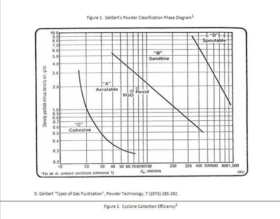
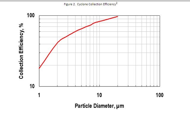
The average particle size is typically manufactured to be in the middle of the Geldart’s “Aeratable” zone (see figure 1) and the smallest particles (0 to 20 µm) are minimized due to FCC cyclones inherent inability to retain those particles (see figure 2).
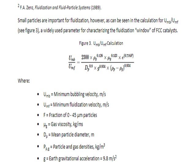
Small particles are important for fluidization, however, as can be seen in the calculation for Umb/Umf (see figure 3), a widely used parameter for characterizing the fluidization “window” of FCC catalysts.
From the equation above, we note that 0 to 45 µm catalyst plays a role in improving the fluidization window. These small particles serve to fill the voids between larger particles and slow down de-aeration of gas from the catalyst.
Maintaining catalyst fluidization at all times is critical to FCC operation. In addition to the health of the catalyst; the unit operations, and the mechanical design and condition of the equipment will all play a role in catalyst fluidization.
If there are no concerns regarding the fluidization of the catalyst in the unit, there may be some benefits to reducing the amount of the smallest particles in the fresh catalyst.
Reducing fresh catalyst 0 to 40 µm material can help reduce stack opacity. The smallest particles have the biggest impact on opacity, as they are closest to the wavelength of the light projected during the opacity measurement, are typically not retained by the cyclones. While fines are generated during the normal circulation of FCC catalyst, reducing the amount coming in with the fresh catalyst can help reduce stack opacity.
If a refinery has developed a hole in their cyclones, and since they are no longer able to retain the small particles in the unit, reducing fresh catalyst fines content can reduce the amount of material passed to either the slurry or scrubber/ESP. This can improve product quality of the slurry oil or reduce waste material handling from the regenerator side. If the refinery has a power recovery expander, this could also help reduce erosion on the turbine.
Grace offers some flexibility in our fresh catalyst formulations to help those refiners who could benefit from reducing fresh catalyst 0 to 40 µm content. Additionally, there are companies that offer catalyst classification and screening. It’s important to work with your supplier to make sure you understand the potential risk and benefits of reducing fresh catalyst 0-40 µm particle content.
Year
2019
Submitter
Process
Question 43: What are your best practices when shipping ecat, fines, feed, and slurry to suppliers for testing? Please also comment on some best practices for sampling equilibrium catalyst.
TODD HOCHHEISER (Johnson Matthey)
When shipping ecat or fines, an appropriate sample container should be used. Catalyst suppliers will typically provide refiners with sample containers if needed. Catalyst shipping containers should be made of plastic or metal. Glass containers are not recommended due to potential breakage but can be used with appropriate packaging. A screw top lid is preferred over a snap on lid sometimes found on metal containers. Prying opening a snap on lid can result in personnel dust exposure. Catalyst samples should not be shipped in plastic sandwich bags or other containers not designed for catalyst service.
JM has found that metal sample containers with a screw top lid are best when shipping low vapor pressure hydrocarbon samples. A best practice is to place the sample container in a plastic bag containing adsorbent pads. These pads should minimize the chance of hydrocarbons leaking out of the box if the sample container leaks.
For hazardous catalyst and hydrocarbon samples, a GHS complaint label must be placed on the sample container. The safety data sheet must also be included with the shipment. Most catalyst suppliers prefer for a safety data sheet to be included even if the sample isn’t considered hazardous. Other regulations and requirements may apply especially for sample shipments between countries.
Common sense precautions are also recommended. Some examples are shipping only the quantity of sample that is required, packaging in strong boxes, and using labels with high quality adhesive. Our lab has received sample boxes containing multiple ecat samples and multiple labels that are no longer attached to the sample containers. Clearly identifying the date of the ecat samples is critical for unit monitoring.
For any sample that is shipped, it is recommended that a company representative certified under DOT or applicable regulations be involved in the packaging and shipping process. Carriers also have specific requirements for shipping hazardous material.
KEN BRYDEN AND LUIS BOUGRAT (W. R. Grace & Co.)
For all samples, it is important to provide a safety data sheet (SDS) when shipping the sample and to follow appropriate Department of Transportation (DOT) and International Air Transport Association (IATA) rules when packaging and sending the sample. Samples should not be sent by U.S. Mail or any service that transfers to U.S. Mail. Based on our experience receiving and testing thousands of customers Ecat and hydrocarbon samples each year, Grace has the following suggestions on best shipping practices.
Ecat and Fines Samples
For Equilibrium catalyst (Ecat) and fines samples, we have found that for routine testing a 500 mL screw top plastic container is an ideal size. Grace provides complimentary Ecat Express containers for this purpose. Screw-top metal containers are another packaging option for Ecat. Glass containers are unsuitable for Ecat since they tend to break in shipment. Containers with paint can lids are unsuitable since the lids tend to come off during shipment and spill catalyst. Bags are also unsuitable containers since they tend to leak. For any container, do not put any tag, string or wire between the cap and the container lid since they will compromise the seal and cause leaking. For large quantities of Ecat, we have found that five-gallon (or 20 liter) plastic screw top buckets are good containers.
For Ecat and fines samples, proper labeling is important in making sure the desired tests are done and reported. At a minimum, samples should be labeled with the following information:
-
Refinery or company name.
-
Refinery location. For example, city and state.
-
Unit Name: Especially important if there is more than one FCC unit at the refinery location.
-
Sample Date: The date that the sample was collected.
-
Sample ID: (Optional) A sample number or name, for your reference.
-
Sample Type: for example, Ecat, fines, purchased Ecat, non-routine, etc.
As part of the complimentary Ecat Express kits, Grace provides container labels that already have the refinery name and unit written and barcoded on the label.
Feed and Oil Slurry Samples
For routine analytical testing to measure the properties of feed or oil slurry samples, a 16-ounce (or 500 mL) sample size is preferred. In shipping hazardous materials, proper packaging and labeling is essential to ensure compliance with the appropriate regulations. This will prevent fines from the carrier and delays in your shipment. In addition, poorly packaged samples can leak, which results in the sample being compromised and thus unsuitable for analysis. There are many good packaging systems available from suppliers that may be chosen to meet the packaging requirements of IATA and CFR49. Which system to use has to be determined by each individual shipper for their samples. The most common system that we see customers use is a 4GV shipper where the hydrocarbon sample is packaged in a metal can, which is then placed inside a plastic bag with an absorbent sleeve. The entire assembly is then placed in a certified cardboard box. It is important to make sure that the lid is screwed on securely. We occasionally receive leaking samples where the container lid vibrated loose in shipment. In preparing containers, make sure tags and wires from labels are not in the thread area of a cap. A string or wire from a label tag put into the sample container, with the cap sealed over it, will act as a wick. This will always cause leaking. Container types that we have noted problems within the past are a) paint cans- the lids often pop off during shipment, and b) glass bottles- they have a tendency to break during shipment.
As with Ecat samples, labeling of feed and slurry oil samples is important. The container should be labeled with the material identity and the appropriate Global Harmonized System (GHS) hazard symbols. Additionally, the sample should be labeled with the following information:
-
Refinery or company name
-
Refinery location: for example, city and state
-
Unit Name: especially important if there is more than one FCC unit at the location
-
Sample Date: the date that the sample was collected
-
Sample ID: (Optional) a sample number or name, for your reference
-
Sample Type: for example, feed, oil slurry, etc.
Process Ecat Sampling
Routine and representative sampling of the circulating Ecat inventory represents a critical part of FCC performance monitoring and optimization. Samples of the circulating inventory should be collected from a fluidized and accessible section of the unit to enable representative sampling of the catalyst system. From a safety standpoint, regenerated catalyst represents an inherently safer sampling source than spent catalyst due to the lack of entrained hydrocarbons and the lower coke concentration along the surface of the catalyst. However, the process temperatures associated with regenerated catalyst are significantly higher than those of spent catalyst and should be mitigated accordingly.
The regenerated catalyst standpipe represents the most common sampling location due to the continuous catalyst flow and accessibility associated with this standpipe. Although the flowing catalyst is well fluidized within this type of standpipe, it is important to properly fluidize the sampling manifold as well when obtaining a catalyst sample. Plant or instrument air are the most common fluidization media for regenerated catalyst sampling stations, which can also be equipped with steam connections to serve as blast points for line plugging troubleshooting. An air or steam purge into the process should be maintained at all times across the standpipe sampling nozzle to prevent catalyst ingress and nozzle plugging. The fluidization medium should correspond to a reliably dry source to prevent potential catalyst agglomeration issues throughout long-term operation. The sampling outlet nozzle should be purged prior to lining up the sampling line to the process to ensure that the manifold is clear of fouling and to confirm that the sample fluidization medium is available and properly dry. The key considerations and best practices for the Ecat sampling process, among others, are as follow:
-
Field personnel should be equipped with all necessary PPE prior to collecting the Ecat sample. Contact your catalyst vendor if any additional feedback or specific PPE guidelines are required.
-
Any potential impacts on instrument readings or safety interlocks by the Ecat sampling process should be thoroughly identified. Ecat sampling activities should be communicated to the board operators prior to starting the sampling process to help ensure that instrument and safety interlock functions are not compromised while sampling.
-
Ensure that the sampling container or recipient is adequately rated for the normal process temperatures associated with the circulating Ecat inventory. The sample containers used for shipping are not typically rated for these elevated temperatures. Metallic containers are typically required to accommodate Ecat sampling.
-
The sampling valve and the sampling outlet nozzle configuration should, ideally, enable sample collection without exposing field personnel to catalyst and entrained flue gas at the high process temperatures. A remote point where the operator can operate a HIC (Hand Indicate Controller) valve to take the sample in line of sight of the sample station but a safe distance away is practiced by several refiners. The sampling recipient can be attached to a long metallic or high-temperature-resistant handle to help mitigate personnel exposure to high temperatures throughout the sampling procedure.
-
Sufficient sample flow should be established to enable collection of a representative Ecat sample. Insufficient purging of the sampling manifold with the flowing Ecat can lead to non-representative or compromised results due to the presence of stagnant Ecat from previous sampling rounds, or other similar contamination sources. Collection of a slip stream during continuous Ecat flow through the sampling line tends to yield a more representative sample than collecting a vial sample from a drum or (large container) of Ecat sample inventory.
-
Excessive superficial velocities through the sampling manifold should be prevented while sampling to help mitigate potential erosion and attrition issues. Excessive catalyst attrition through the sampling line can lead to false PSD profiles for the circulating catalyst inventory that can prompt unnecessary troubleshooting activities. Adequate velocities through the sampling nozzle also help reduce turbulence and dust as the flowing Ecat reaches the sampling container, thus preserving as much of the fines content present in the circulating inventory as possible.
-
A pint of Ecat sample is usually sufficient volume to accommodate routine lab testing for process monitoring purposes. Excess Ecat sampling volume should be properly handled and discarded via spent catalyst drums or disposal lines routed to the spent catalyst hopper, if available.
-
Ecat samples should be allowed to properly cool before filling the corresponding shipping containers. Windy or wet environments should be avoided for the cooling period to avoid altering the physical properties of the Ecat sample.
The guidelines and best practices previously referenced should be followed when shipping the Ecat sample containers. Board operators, unit engineers and other supporting staff for the FCC complex should visually inspect Ecat samples before the sample is shipped to the catalyst vendor. Visual inspection can help qualitatively gauge the health of the circulating catalyst inventory – especially with respect to coke on regenerated catalyst (CRC), drastic PSD shifts, and/or potential Fe poisoning contamination – well before the corresponding lab results become available.
Year
2019
Process
Question 50: What methods or operating parameters do you use to monitor/diagnose FCCU regenerator air and catalyst maldistribution? What can be done operationally to mitigate air and catalyst maldistribution? What mechanical changes have been successful at improving air and catalyst distribution?
DAVID HUNT (W. R. Grace & Co.)
Maldistribution of air and/or spent catalyst can be diagnosed by several different symptoms.
Localized regenerator afterburn is a common symptom of non-optimal air and/or spent catalyst distribution. Regional CO bed breakthrough will combust and afterburn in the regenerator dilute phase and cyclones indicating a stochiometric imbalance of air and coke. In a partial combustion operation, localized afterburn confirms confined oxygen breakthrough from the bed resulting in CO combustion in the dilute phase and cyclones. The use of combustion promoter in either operation (full or partial combustion) is commonly used to reduce afterburn for FCCU’s with non-ideal air and spent catalyst distribution.
Excessive catalyst losses are another symptom of poor air distribution resulting in localized high catalyst entrainment exceeding the capacity of the cyclones in that region of the regenerator. High velocity from a partially plugged distributor could also increase catalyst attrition producing higher catalyst losses.
Poor air distribution may also result in zones of de-fluidized catalysts within in the regenerator. High catalyst losses maybe observed due to cyclone diplegs attempting to discharge into the de-fluidized zone resulting in dipleg backup. If the regenerated catalyst enters the standpipe from any zone of de-fluidized catalyst, poor pressure builds in the standpipe maybe observed reducing unit catalyst circulation capacity or stability.
A change in air or spent catalyst distribution may also be identified by a shift in temperatures within the bed, dilute phase or cyclone outlet. Ideally these temperatures will all be similar, say within +/- 10°F. If the temperature difference increases suddenly, over time or across a shutdown then a deterioration of air or spent catalyst distribution may have occurred. Or in similar fashion if the cyclone with the historical “hottest” outlet temperature reduces and another cyclone moves to the “hottest” position then the refinery might suspect an air or spent catalyst distribution change.
Dark catalyst particles observed when the regenerated catalyst has a “salt and pepper” appearance is also a confirmation of non-ideal spent catalyst distribution and/or air maldistribution. An experienced operator “eye” is valuable in this instance.
Refiners should monitor air distributor differential pressure (dP) and compare against the expected dP calculated from the distributor design and operating conditions. Lower than expected air distributor dP suggests damage such as a hole, worn restriction orifices or distributor-arm separation from the header. Higher than expected dP could mean a partially plugged distributor. Both issues can result in non-optimal air distribution.
The air distributor minimum dP should be maintained within licensor requirements. Minimum dP is generally maintained within a fraction of the catalyst bed differential pressure or height. Higher bed heights will require additional distributor dP to assure air distribution across the bed and to avoid catalyst ingress within the air distributor. Downward pointed distributor nozzles may require less dP relative to upward pointed nozzles. In general, a minimum dP of 1.0 psi is adequate for most circumstances.
It’s difficult to significantly alter the air and spent catalyst distribution while operating. If poor air or spent catalyst distribution is resulting in afterburning or high catalyst losses which are constraining the unit, the operator may consider the following:
-
Use of a combustion promoter: semi-continuous injection of promoter or premixing with fresh catalyst is often more beneficial than of one or two daily injections
-
Air placement optimization for regenerator designs with multiple air rings or air distributors
-
Bed level optimization to minimize afterburn (generally higher bed height) or catalyst losses (generally lower bed height)
-
Use of supplemental O2 to reduce catalyst entrainment and losses
-
Higher regenerator pressure to reduce catalyst entrainment and improve combustion kinetics
Non-ideal spent catalyst distribution remains a challenge in today’s FCCU’s despite continuous technology advancement over the last 75 years. Surprisingly, regenerators with symmetric spent catalyst distribution and robust air distributor designs in good mechanical condition can observe afterburn suggesting non-ideal air and spent catalyst distribution.
Computational Fluid Dynamic (CFD) modeling is a useful tool to confirm spent catalyst distribution for a given design and evaluate design options. (1) Optimized delivery of the catalyst to the spent catalyst distributor can also be evaluated by CFD. Licensors offer these services as part of their study and design work as well as other consulting firms.
Finally, gamma scans and radiotracer evaluations are useful studies to confirm air and/or spent catalyst distribution and provide a justification to make planned repairs or modifications during an upcoming turnaround or unit shutdown. (2)
-
Simulation as a Tool for Learning from Historical FCCU Operations, Sam Clark, AFPM Cat Cracker Meeting, 2018, Houston TX, CAT 18-980
-
FCC Regenerator Catalyst Loss Case Study, William Mixon (Tracerco), Nicolas Larsen (Marathon Petroleum Corporation), APFM Cat Cracker Meeting, 2018, Houston TX, CAT 18-653
CHRIS STEVES and ZHEN FAN (Norton Engineering Consultants, Inc.)
Looking at the afterburn (if in full burn operation) and the distribution of that afterburn at each cyclone is the primary way to evaluate the regenerator air/catalyst distribution. Cyclones with a high afterburn are probably coke rich/air deficient and CO gas from the regenerator bed is mixing with excess O2 from an oxygen rich section of the bed and causing a high afterburn. Poor air/catalyst distribution can either be a result of the design of the unit, or mechanical damage to the air grid/ring or catalyst distribution system that should be repaired during the next available turnaround.
The distribution of air from the air ring may be impacted by bed level in the regenerator, and adjustments to the bed level can be used to evaluate the impact on afterburn. Of course, running with a higher regenerator bed level may impact catalyst losses and needs to be balanced against any potential improvement in air distribution and afterburn.
Year
2019
Process
Question 48: What is your experience with carbon on regenerated catalyst levels in partial burn operations? How do you confirm an optimal level of carbon to ensure desired product yields? How do metal amounts or feedstock play a role in controlling carbon on regenerated catalyst?
TODD HOCHHEISER (Johnson Matthey)
The optimal level of carbon on regenerated catalyst (CRC) is often a balance between conversion and feed rate. Lowering CRC can be achieved by increasing air rate. In FCCs that are air blower or regenerator temperature limited, this can result in a feed rate reduction or residue processing reduction. The benefit of operating at the lower CRC is increased ecat activity and conversion.
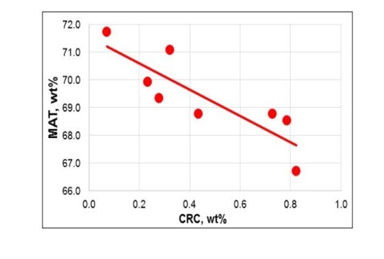
The JM laboratory conducted an expert with a spent catalyst sample. The spent catalyst contained 1.2 wt% carbon and was taken from a two stage FCC unit processing residue feed. The sample was divided, and the coke was burned off to varying levels ranging from 0.07 wt% to 0.82 wt%. Each sample was then processed on a ACE unit. MAT decreased by 1 wt% for each 0.2 wt% increase in CRC (see Figure). The activity loss slope will be specific to the FCC, catalyst type, and ACE testing protocol.
Another method to evaluate the impact of CRC on activity is based on routine ecat testing. Ecat activity results are usually reported after calcining the sample. ACE testing can also be conducted on the sample prior to calcining. The activity gain from calcining shows the impact CRC has on that particular sample. A trend can be developed by plotting the activity delta from calcining versus CRC.
When operating at higher CRC, delta coke is reduced. For units that are delta coke limited, the right balance needs to be found between CRC and delta coke. If feed metals are increased, delta coke will increase. One method to combat the higher metals is to raise CRC thereby lowering delta coke. In this scenario, the higher metals will impact conversion negatively for two reasons: ecat metals poisoning and operating at higher CRC.
Catalyst formulation can be evaluated to switch to a lower delta coke catalyst. This will allow lower CRC while still staying within regenerator temperature limits. Metal trapping additives can also be used to reduce delta coke.
DAVID HUNT (W. R. Grace & Co.)
FCCU partial combustion operation brings additional operating complexity relative to a full combustion regenerator operation. Before equilibrium catalyst activity is measured by the catalyst supplier, coke is traditionally burned clean, and the activity is reported on a carbon free basis. For operations where carbon on regenerator catalyst is greater than ~ 0.25 wt.% the effective in unit equilibrium catalyst activity may be less than the reported value.
Excessive carbon level can be a process safety risk in addition to producing high slurry oil and lower conversion. Carbon will generally cover the most active sites enriched with the youngest catalyst fraction.
The amount of carbon on the regenerated catalyst is influenced by several factors including the following:
- Feedstock and recycle rates
- Feedstock properties (Conradson carbon)
- Regenerator combustion air rate
- Flue gas carbon monoxide (CO)
- Regenerator temperature
- Regenerator and riser residence time
- Catalyst activity
- Metals
- CO combustion activity
- Additives
- Particle Size Distribution
Excessive carbon on regenerated catalyst is often a challenge for constrained units operating a partial combustion regenerator at increased feed rates with heavier feedstocks.
When feedstock Conradson carbon levels increase additional coke is deposited onto the catalyst in the riser. Since the regenerator operates with no excess oxygen, the incremental coke on catalyst increases CO levels and finally carbon on regenerated catalyst for the same combustion air rate. Slurry recycle produces an even more dramatic effect due to the relatively high Conradson carbon level.
Dehydrogenation metals such as nickel and vanadium behave in a similar fashion as Conradson carbon. In the riser delta coke on catalyst increases with these metals moving the regenerator into a deeper partial burn with higher carbon on regenerated catalyst at fixed operating conditions.
Excessive CO combustion activity can strongly drive the C + O2 > CO2 combustion reaction versus C + 1/2O2 > CO consuming more oxygen relative to carbon increasing carbon levels on the catalyst.
Increased average particle size has been linked to higher carbon on regenerated catalyst. Increased regenerator bubble size and less mass transfer to the emulsion was suspected. (1)
Slow combustion kinetics at low regenerator temperature have caused high carbon levels. (1)
Grace is also aware of instances where high levels of “hard coke” are observed on regenerated catalyst where traditional regenerator temperatures are unable to burn the catalyst clean. Several factors are believed to be at play. Grace has worked closely with our customers in those instances to optimize the unit and bring carbon levels back to acceptable levels.
Generally lower catalyst activity and an increased amount of metal trapping are required to reduce delta coke and maintain optimal levels of carbon on regenerated catalyst in a constrained partial combustion regenerator operation with residual feedstocks. Working with your catalyst supplier to continuously optimize the catalyst and partial combustion operation is highly recommended to ensure a profitable and safe operation.
- Indian Refiner Presents Troubleshooting Examples for a Partial Combustion FCC Regenerator, Das et al, Oil and Gas Journal, Sept 4, 2000
CHRIS STEVES (Norton Engineering Consultants, Inc.)
The catalyst and air distribution in a partial burn FCC regenerator will have an impact on the carbon on regenerated catalyst, as well as the operation (primarily regenerator temperatures). The impact on yields for different CRC levels will depend on the feed quality and the catalyst type and should be evaluated through unit testing and trending of historical information, taking care to compare periods with similar feed types and catalyst types.
Year
2019
Process
Question 39: What are your best practices for transferring FCC catalyst into/from pneumatic trailers and rail cars to ensure personnel safety and catalyst containment?
TODD HOCHHEISER (Johnson Matthey)
These trailers are often referred to as pneumatic, dry bulk, or pressure differential (PD) trailers. On-road trailers and railcars have similar functionality although railcars are not usually rated for vacuum, nor do they usually have a filter system. Both types of transport vessels have multiple hoppers. The multiple hoppers are necessary to make sure that the outlet slope is greater than the angle of repose.
A trailer can be offloaded into either an atmospheric pressure hopper or a hopper under vacuum. A vacuum is not required but can increase the offload rate. Once the trailer arrives at the offloading location, the wheels should be chocked, and the trailer grounded. Proper PPE should be worn. The trailer outlet line is then connected to the refinery piping using a flexible hose. All those connections should be locked. It is best to match the diameter of the trailer discharge piping, hose, and refinery piping. If the refinery piping diameter is larger, additional carrier air may need to be added.
There are 3 air uses in a typical trailer: top air for trailer pressurization, carrier air, and aeration air. The air for trailers is usually provided by the truck blower while air used to offload railcars is provided by the refinery. The refinery storage hopper design pressure and relief valve capacity should be checked against blower design. A filter may be needed on the refinery hopper discharge vent. Some factors that contribute to whether a filter is needed are hopper air velocity, hopper catalyst level, and whether a vacuum system is used on the hopper. A filter is recommended upstream of the refinery vacuum system to minimize erosion in the ejector.
Most trailers and railcars have a design pressure of 15-18 psig. Top air is introduced into the trailer between 8 and 12 psig. Carrier air is introduced into the outlet piping upstream of the trailer hoppers. Setting the carrier air flow is part art and part science. Carrier air velocity is recommended to be 10-20 ft/sec. Measurement of carrier air flow is uncommon; therefore, the flow setting is often set based on experience. Some hoppers also include aeration air which can be used to fluff the catalyst. Once the trailer is suspected to be empty, a visual inspection from the top hatches should be performed. Some trailers have handrails on top for increased safety when accessing the hatches. Proper tie-off is required when on top of the trailer. Trailer pressure should be verified as zero prior to opening hatches.
When loading a trailer, the trailer should first be verified as empty and clean by visual inspection. Trailer loading can be accomplished via gravity flow, pressurization of the refinery hopper, or by pulling a vacuum on the trailer. Gravity flow requires a loading facility where the trailer can be located underneath the hopper. The trailer vent for the displaced air is usually routed to atmosphere due to minimal flow. The second option for loading a trailer is to pressurize the catalyst hopper and add carrier air at the outlet of the hopper. In this scenario, the trailer relief valve capacity needs to be evaluated. Additionally, a filter system is necessary on the trailer vent. This can be a filter system included with the trailer or the vent can be connected to a filter system at the refinery. Another option for trailer loading is to utilize a vacuum system. This option is not readily available for railcars. The vacuum source for the trailer is typically the truck blower pulling suction from the trailer through a filter. For vacuum filling, there are usually multiple fill lines as it is difficult to fill more than two compartments from a single inlet. Most trailers have weight gauges to help prevent overfilling and help determine when to switch hoppers.
LUIS BOUGRAT (W. R. Grace & Co.)
FCC catalyst handling activities constitute an important piece of day-to-day unit operation that can have a tangible impact on operational safety and performance. The health of the circulating catalyst inventory is highly dependent on the success of the routine fresh catalyst transfer process from the delivery vessel to the fresh catalyst hopper – or equivalent recipient.
General Catalyst Transfer Guidelines
From a safety perspective, the key is to identify and actively monitor the mechanical design limits of the lines, fittings and equipment involved throughout each step of the catalyst handling activities. It also becomes critical to properly ground all loading/unloading vessels, equipment and piping/hoses to avoid static electricity hazards. Regardless of the procedural complexity of the material loading/unloading process, a good practice is to at least verify the following items prior to any loading or unloading activities:
1. The shipping truck, or alternative delivery medium, has been properly secured from movement by at least two independent means.
2. Correct lineups of the hose, hopper and corresponding piping. If applicable, any hose connections should be properly secured at each end.
3. Correct valve positions to ensure safe and adequate catalyst routing and flow control. Ensure that the correct material is lined up to the correct storage hopper or recipient.
4. Visual inspection of all equipment and fittings associated with the procedures to ensure that they are in proper working condition.
5. Confirm hopper inventory prior to loading the hopper to prevent overfilling and potential loss of containment.
6. Operators should observe the entire loading process, never leaving the loading process unattended.
All personnel involved in the catalyst handling activities should also adhere to the PPE requirements associated with the local policies and regulations at all times. Permissible exposure levels of the various components in the catalyst are present in the product safety data sheets and should be reviewed with monitoring performed when needed.
Considerations for Catalyst Loading to a Fresh Hopper
Fresh catalyst is typically delivered in railcars or trucks when shipped within North America. The specialized trucks can typically deliver 20 to 25 tons based on multiple factors and regulations, and railcars can carry roughly 80 to 90 tons. The maximum allowable loading limit for individual trucks should always be observed while leaving any necessary clearance within the load compartment for pressurization and depressurization requirements. Apart from potential impacts to transportation safety, overloading of the truck or railcar can also lead to undesired catalyst handling losses that are often costly and may result in employee, public and environmental exposures. All catalyst loading and unloading activities are usually carried out through pressure differentials or gravity feeding. Silo or tank trucks are typically pressurized while the fresh catalyst hopper is placed under a vacuum, using steam ejectors, to establish an adequate driving force for catalyst flow. Prior to pulling a vacuum within a truck, storage hopper, or any other vessel, it is critical to ensure that the corresponding system is rated for the targeted vacuum conditions. Establishing an excessive vacuum within a vessel or delivery medium not rated for this type of service can lead to personal injury, irreversible mechanical damage that can also compromise the catalyst containment efficacy of the system. Railcars are not typically rated for vacuum service. As such, a corresponding lid should be opened, or at least partially cracked, during catalyst transfer activities to prevent the buildup of negative pressure.
Catalyst loading and unloading activities are highly dependent on the mechanical integrity of the piping and fittings connecting the trucks and storage hoppers. Fouled piping or fittings can significantly deter catalyst transfer efficiency while potentially posing a back-pressure hazard to upstream equipment. Therefore, adequate debris screens should be installed and frequently inspected at the bottom of storage hoppers to help prevent plugging hazards. Catalyst manufacturers have quality assurance controls at the manufacturing plants to prevent debris ingress into the delivery medium. The catalyst should be kept dry and free of contamination throughout the catalyst handling activities to ensure proper flow characteristics. Any carrier air or fluffing air supplies should be regulated and maintained adequately dry at all times, particularly in winter service. Steam ejectors for vacuum service can also introduce moisture into the system and lead to catalyst agglomeration issues.
The carrier air rates should be controlled such that the superficial velocity through the catalyst transfer lines is maintained at 10 to 20 ft/s at all times. Excessive line velocities can lead to accelerated wear of the piping and internals based on the high loading and unloading frequency for typical FCC units. Long-radius elbows and cushioned tees help mitigate erosion across any change in piping direction but can still be susceptible to mechanical wear throughout long-term operation. Ceramic, cast basalt, and/or alumina linings can be used for susceptible piping sections to improve mechanical resiliency throughout catalyst transfer cycles.
Considerations for Catalyst Unloading from a Spent Hopper
With respect to catalyst withdrawal from the regenerator and spent catalyst hopper, the same considerations and best practices apply. However, there is also an increased focus on catalyst temperature throughout the catalyst transfer activities. The mechanical design limits for the transfer piping, spent catalyst hopper and truck or railcar containers should be observed at all times. Adequate insulation or PPE requirements should be established to properly protect field personnel from the high temperatures associated with this type of activity. Entrained flue gas from the regenerator should also be accounted for throughout safety assessments and procedure development. Catalyst temperatures can usually be controlled by controlling the rate of spent catalyst withdrawal from the regenerator and storage hopper residence time. The superficial velocity limits for the catalyst transfer lines should still be observed and the higher temperatures should be taken into account.
Considerations for Emissions Control
Engineering controls are the preferred means to control personnel exposure. The use of closed systems for storage, dustless systems for material transfer, ventilation for industrial hygiene and dust collection are all highly recommended. Good housekeeping practices should be employed to reduce airborne material and the accumulation of settled dust. Vacuum systems should be equipped with High Efficiency Particulate Air (HEPA) filters. Dry sweeping is to be avoided as it can result in re-distribution of material. Airborne dust levels must not exceed the permissible exposure limits (PELs) that are found in section 8 of the product MSDS. Be aware that it is very difficult to visually determine airborne concentration of dust.
The actual level within the hopper or storage vessel should be frequently monitored via manual gauging or reliable instrumentation for particulate service. Overfilling of the storage hopper represents a common root cause of excessive catalyst handling losses and emissions throughout catalyst loading and unloading activities
Year
2019
Process