Question 1: What is your best practice for safe and quick decontamination of solid media beds?
ABIGAIL SLATER (HollyFrontier)
Safe and quick decontamination of solid media beds requires a good working knowledge of the unit, the bed material, and the nature of the contamination. Media beds include feed filter-coalescer elements, reactors, guard bed reactors, chloride guard beds, sulfur guard beds, etc. The nature of the contamination may involve any number of biological, organic or inorganic materials which present hazards to handling the media after service.
Generally, the decontamination of solid media involves bringing Lower Explosive Limits (LEL), Hydrogen Sulfide (H2S), and benzene into acceptable ranges. Decontamination practices are also used to passivate pyrophoric or self-heating catalysts, which present safety hazards when exposed to oxygen.
One of the most common contamination issues is that of adsorbed benzene – a well-recognized toxic material. Benzene can sometimes absorb on the walls of the vessel or the media. A great deal of time can be lost in decontaminating solid media and the unit as a whole. For that reason, many solid media beds are often dumped or vacuumed out under an inert atmosphere. A hot hydrogen purge, followed by a hot nitrogen purge, is typically successful in liquid-freeing the solid media bed but not always successful in removing LELs and benzene. Hot hydrogen, or even fuel gas, can be used when nitrogen is not readily or easily available, this serves as a cost saver but must be followed by a hot nitrogen purge.
Another method to benzene free a vessel is steam out. However, many operators have found this approach to be inefficient, often requiring multiple steam out attempts, and hence, extra time to bring residual benzene levels down to within acceptable exposure limits. Steam out can also cause undesired results. For example, steaming out a chloride guard bed can potentially increase the corrosivity or even react violently with the media inside the vessel. Therefore, many have turned to using nitrogen and chemical cleaning to more quickly benzene free solid media beds and the unit in general.
An increasingly popular method to decontaminate LELs, H2S, and benzene has been to chemical clean. Some companies have produced proprietary organic chemicals which have proven to be successful at freeing a unit of LEL, H2S, and benzene. The chemical cleaning technique is to inject the chemical during the cool down step while circulating the chemical for a designated time. The H2S is first scavenged, and then the hydrocarbon is displaced to flare. Once the chemical cleaning is complete, the unit or vessel is swept with nitrogen. An added benefit of chemical cleaning is that it generally reduces decontamination time by several hours, or even days, by reducing the time to hold a hot nitrogen purge. This is a large economic driver. It can also reduce the safety hazards of working in an inert atmosphere.
Overall, the decontamination of a solid media bed will greatly depend on the application of the vessel. Hot nitrogen purge and steam out is a tried and true method to reduce LEL, H2S, and benzene levels, but it takes a large amount of time and the vessels are still held under an inert atmosphere. Chemical cleaning is becoming more popular and is proving to be successful and reduces decontamination time by several hours or days.
THOMAS PORRITT (Chevron U.S.A.) (2)
My company has had limited success reaching acceptable benzene and lower explosive limit levels when cleaning media beds with hot nitrogen. For that reason, whenever possible, we choose solid media that is tolerant of steam during the cleaning phase. This allows us to clean and dump the beds more efficiently. For steam cleaning to be effective we have found that flow is a key factor. The flow should be enough to avoid forming condensate in the vessel.
DAVINDER MITTAL (HPCL-Mittal Energy)
The methods and processes for decontamination of solid media beds largely depend upon the final objective to be achieved such as replacement of full charge of solid media in reactor system, replacement of one or more beds or only skimming of catalyst bed, reactor inspection only after unloading catalyst or bottling up of the unit due to a longer shutdown.
Different methods are available specific to the unit depending upon whether it is a hydro-processing unit or some other unit.
For hydro-processing units, most people still prefer conventional proven methods like hot hydrogen stripping with a minimum required hydrogen sulfide content in recycle gas to avoid catalyst reduction followed by cold hydrogen stripping, depressurization and nitrogen purging for skimming, partial replacement of catalyst, bottling up of unit due to longer shutdown or only Reactor inspection.
The full charge replacement is relatively less cumbersome as it requires plain hot hydrogen strip without hassles of maintaining a minimum hydrogen sulfide followed by cold hydrogen stripping, depressurization and nitrogen purging before catalyst unloading.
Hot nitrogen stripping or water flooding (aqueous solution of soda ash) is also practiced at times to reduce LEL before unloading of catalyst. Hot nitrogen stripping is a costlier option while reusability of catalyst is lost after water flooding.
The catalyst unloading or reactor man entry is essentially done under nitrogen in both the above cases.
A proprietary catalyst passivation technology and actual case studies are available to eliminate hot hydrogen strip during catalyst decontamination before unloading. Majority of cooling happens under liquid oil circulation thereby reducing conventional unloading time. The technique, passivates pyrophoric or self-heating catalysts by application of a catalyst coating material during special liquid circulation step. The catalyst and equipment surface are coated with an organic film which retards oxygen penetration and reaction providing significant stabilization. The passivated catalysts can be unloaded safely under air thus eliminating hazards related to inert entry. The most important feature of this technology is that it eliminates the life threatening nature of working in a nitrogen atmosphere. Safety is further enhanced by handling passivated catalyst and minimizing hazardous dust normally present with catalyst removal. Another important feature of the technology is that catalyst remains fully re-generable. The technology has successful references for more than 200 reactors till date and has been licensed for application in Europe and Middle East.
One more patented technology is available wherein a proprietary organic chemical (Distillation range: 330- 380oF, Vapor pressure: 1.4 mm Hg at 20oC) is injected during gas sweep process in the unit. The injection takes 4 to 5 hours and the displaced hydrocarbons are routed to flare and slop. The technique claims to shorten decontamination time lines, reduce or eliminate hot hydrogen strip step, no residue LEL and reduction in nitrogen requirement.
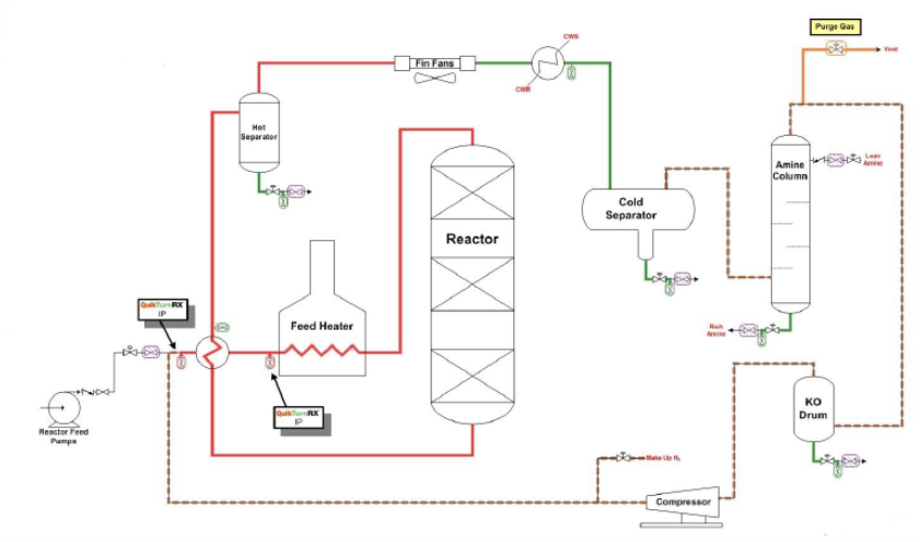
Picture-1: Typical scheme showing possible injection location of organic chemical
Also, the proprietary techniques are available for accelerated cooling of the solid media during cool out phase of decontamination which saves significant cooling and purging time for refinery process units like hydrocrackers, hydro-treaters and reformers, where catalyst handling is often a critical path activity. In this technique, typically, liquid nitrogen is injected in a controlled manner through proprietary equipment into the recycle gas stream to cool the gas before the gas enters the reactor. It is claimed that this technique requires about 1/3rd the amount of nitrogen as required in once through cool down.
For CCR and ISOM, the technology suppliers generally rely on conventional techniques for catalyst decontamination as the procedure is not as complex as in hydro-processing units.
The dry hydrogen stripping of catalyst followed by blinding and sweeping with cold dry nitrogen is followed in ISOM unit and the catalyst is unloaded under nitrogen atmosphere. For CCR, hot hydrogen stripping followed by cooling with recirculating hydrogen and nitrogen is conventional before unloading of catalyst from bottom of reactor/regenerator under nitrogen.
For chloride adsorbents in ISOM and CCR, the nitrogen stripping generally suffices for decontamination before unloading of adsorbent.
For sulfur guard in NHT for example, the drum may be flooded with clean water for decontamination, if vessel and foundation design permits and catalyst may be unloaded in wet condition.
Year
2019
Process
Question 76 The regeneration of feed dryers/sulfur guard beds on butane isomerization units generates a butane slop stream. Will processing this butane slop stream in an HF or sulfuric acid alkylation unit cause any problems? If so, what else may be done with this slop stream?
QUINTANA (Valero Energy Corporation)
The spent Isom regenerant will contain butanes that are attractive to recover. They can come from generally any of three sources: either the treated normal butane feed downstream of the on-stream dryer, the fractionated isobutene from the Deisobutanizer fractionator overhead, or the isomerate product is used as the regenerant source. The spent regenerant also contains all of the sulfur and oxygenate impurities that were previously accumulated on the sieve; and after the spent regenerant coalescer, it will also be saturated with water. We should also keep in mind that these impurities will generally co-boil with the normal butanes since that’s how they got to the Isom feed dryer to begin with. This should be kept in mind when determining disposition of the spent regenerant. Furthermore, while the impurity concentrations vary during the regeneration, you will generally hit a peak during hottest part of the regeneration as well. That high level can possibly overload some of the downstream systems that the regenerant is directed to.
The spent regenerant may be attractive to recover as alkylation unit feed, especially where it has significant amounts of isobutene. Clearly, if you’re using the Isom feed (with low amounts of isobutene) as your regenerant, then it’s just going to take up hydraulic space in the alky unit, and another alternative may be preferred.
The feed dryers at the alky unit won’t remove much of these impurities other than moisture with three primary consequences. You’ll get consumption of acid from sulfur and oxygenate reactions, but they won’t be completely converted. Then, these acid consumption byproducts will increase the load on the acid regenerator while the unconverted impurities that remain will end up back in the fractionated normal butane cut that goes to the Isom unit feed. As a result of that, the recycled impurities from the spent regenerant will add on to the level that is in the fresh C4 feed. As the level builds, it will wind up in the feed to the Isom dryers and potentially overload it, leading to breakthrough between regenerations, and possibly deactivate Isom catalyst.
The windup effect is illustrated in this figure where the dotted line represents the recycle of the spent regenerant to the alky feed. Each time a regeneration is under way, the impurity level in the alky unit will likely increase, which will increase that load on the alky regenerator and produce more ASO. And as Allen indicated back in Question 72, oxygenates in an HF unit are particularly a problem as they will make lighter ASO compounds. We’ve seen as much as a 100°F drop in the ASO IBP from oxygenates in alky unit feeds. In order to get rid of those byproducts in the acid regenerator, you have to drop your regenerator cut-point, which will substantially increase the physical acid losses that go out with the spent regenerant.
Since the conversion of the impurities to ASO compounds is not complete, those residual impurities in an alky unit will wind up, again, in the Isom feed and load up the dryers, and the cycle is repeated. The tolerance of a given unit to that wind-up really depends on the amount of available dryer capacity. But if you have a unit that has increased throughput over the years and you have less time between regenerations, you may not have enough drier capacity between regenerations to tolerate that wind-up. And additionally, depending on how much sulfur you have in the refinery, clearly that will have an impact on how much load there is on those dryers as well.
So the most effective alternative is to break the wind-up loop and not have a recycle that’s going to contribute to that increased concentration and basically send the spent regenerant to where it can be more completely converted. What we found to be most effective is to send it to a hydrotreating unit, typically the naphtha unit, and there the impurities will be completely converted; subsequently, the treated butanes can combine with other refinery butanes and be sent back to the Isom feed. In this way, you don’t have the accumulation effect described earlier.
Gasoline ProcessesGasoline Processes•Tolerance to sulfur wind-up varies with the amount of slack drier capacity, amount of sulfur in the refineryIsom Regenerant DispositionAlky UnitDIBIsomDriersIsomUnitAlkylateSpent IsomRegenerantC4 FeedASOiC4 RecyclenC4
Other alternatives can include fueling spent regenerant although that depends on the refinery fuel balance and may present an economic downgrade of butane. It may also affect stack emissions because of the sulfur compounds in that regenerant. Alternately, you could recycle it further upstream to the butane sweetening unit; but again, you’re not going to get as completed conversion as in the hydrotreating unit itself.
We have seen some units, in my previous days at UOP overseas, that were equipped with a large spent regenerant drum that was large enough to contain all of the spent regenerants from the full regeneration. That way, variability of the contaminant concentration could be limited and it could be sent ratably to the downstream destination.
METKA (Sunoco, Inc.)
We operate a Butamer within our HF alky complex. Originally, normal butane was used as the dryer guard bed regenerant, and we routed the spent stream to gasoline blending. Over the years, we had no reported issues resulting from this operation. Approximately three years ago, we performed a study to evaluate using stabilizers bottoms from the Butamer as the regenerant stream and then subsequently reprocessing it in the alky.
The stabilizer bottoms is a dry stream and its relatively high isobutane content results in less alkylation unit impact than would be expected with a normal butane stream. As part of the study, the cycle up of contaminants that Javier discussed was reviewed and its potential impact on the unit was determined to be manageable. We made the piping modifications to route the stabilizer bottoms to the guard beds and to also allow the spent stream to be rerouted back to the HF alky where it is treated and then dried with the BB feed. We’ve had no adverse effects to date with this operation.
Year
2008
Process
Question 77 What is your experience with cooling water exchangers in an HF alkylation unit? How long do you go between cleanings? Do you have a special water treatment program for cooling towers dedicated to the alkylation unit?
KAISER (Delek Refining Ltd.)
In my experience, the cooling water exchangers in an HF alkylation unit are really no more problematic than any other exchanger in the refinery when you’re looking at the waterside only. If you have an exchanger in the HF alkylation unit that suffers from low flow or it’s at the end of a header, trapped scale, and there are certainly critical exchangers inside the alkylation unit that you want to keep clean, it’s really no different if it’s in the alkylation unit or in some other unit in the refinery. You’re going to have water problems and that’s going to generate issues for you.
Generally, what I’ve been able to see is that most of those exchangers will tend to make two to three years. Some of them will go longer than that—four to five, depending on what service they’re in. The things that I’ve seen is that we’ll typically have process-side corrosion issues that generate leaks and that would force us to take that exchanger offline for repair any cleaning before we had significant enough fouling on the waterside solely to force a cleaning by itself.
Both alkylation units that I have experience with have their own dedicated cooling towers. Whether that’s by choice or by design, I’m not sure. What it does allow you to do is minimize the impact of any leaks upon any other process unit or refinery. And certainly when you have a leak in any acid service, be it sulfuric or HF, the key is to track down which exchanger is leaking rapidly and isolate that from the cooling water system so that you minimize damage to your cooling water circuits. Most refineries will tend to monitor pH, ORP (oxidation reduction potential), fluoride, or some combination of these, either on a shift or continuous basis, to help them determine when they have a leak.
Most cooling towers will operate a fairly standard cooling water package. They’ll use phosphates for corrosion control, polymer dispersants, and various other bits and pieces of chemicals. It’s nothing really any different than what you would use in any other cooling tower in the refinery.
METKA (Sunoco, Inc.)
Sunoco has a separate cooling tower at the HF alky complex as well. Our experience is very similar to what was just discussed. We don’t have a special chemical treatment program. We do perform additional pH monitoring for leak detection, and the process side can limit the run for several services.
ZMICH (UOP LLC)
I would like to share some thoughts provided by our Tech Service experts in our Engineering department. At UOP, we have seen corrosion in cooling water exchangers and
alkylation units on both process and water side. Typically, the corrosion rate on the process side of the reactor bundles and on the acid cooler bundles is relatively low at normal conditions, but excessive temperature or higher concentration of percent water in the circulating acid can cause corrosion and plugging on the process side.
Refiners have reported corrosion rates on the process side of water cool condensers, especially if the water content of the circulating acid is high. Low water flow rate can lead to fouling of the tubes from biological growth or calcium scaling, both of which can lead to under-deposit corrosion. Inadequate treatment or blowdown of the cooling water can also cause corrosion on the water side of these exchangers.
An important point is UOP strongly recommends a separate cooling water tower for HF alkylation service, and I believe we include that in our new unit design specifications.
Finally, at UOP, we have seen some new unit activity for alkylation units. Generally speaking, permitting does not prohibit installation of an alkylation unit; but if one is considering addition of an alkylation unit, it should go through what’s considered a quality-risk assessment.
MIKE FACKER (Western Refining Company)
We have a couple of heat exchangers, water coolers, ahead of our KOH, and there’s a temperature limitation there. I am wondering how people try to limit their temperature at that point, whether you try to do it on the water side and take your fouling there. I understand there’s about 100°F limit you want to go into your KOH system. Are you all familiar with that part of the treating or do you know what you do for temperature control there?
KAISER (Delek Refining Ltd.)
What service are these in?
MIKE FACKER (Western Refining Company)
This is behind the alumina.
KAISER (Delek Refining Ltd.)
Is this on propane or alkylate?
MIKE FACKER (Western Refining Company)
Well, we have both propane and butane. The coolers go under the KOH and it is HF, yes.
KAISER (Delek Refining Ltd.)
And this is off your isostripper and depropanizer towers?
MIKE FACKER (Western Refining Company)
Right.
KAISER (Delek Refining Ltd.)
There’s generally not a better cold-sink anywhere than the cooling water, and cooling water is typically used there, from what I’ve seen. No, there’s not a whole lot you can do other than take the hit on the water side and suffer through some high skin temperatures. The thing that you ought to try and do as best you can is to work with your water vendor and do your best to keep the cooling water as clean and solids-free as it can be. You might have to give up some cycles on your cooling tower, get the total dissolved solids down, and keep a close eye on your phosphate.
The other thing that your water vendor ought to be able to do is help you understand what your failure mechanism is. Is it the calcium carbonate? Is it silicate carbonate? Then, maybe the vendor can tailor the water treatment program a little bit more specifically around these particular exchangers if they foul out. The best case situation, which you probably don’t have, is parallel exchangers where you’ll be able to switch back and forth between the two and just plan on a routine cleaning before the deposition gets bad enough to precipitate an under-deposit corrosion.
METKA (Sunoco, Inc.)
That particular service has not typically been a problem for us on the process side, but it has had some issues on the water side. In some of these problem services, we’ve had the opportunity to install some piping connections and we’ve put a little rental booster pump in for the summer operation to increase the pressure and get a little bit more water flow. We have also used the same methods to address water side issues that Allen discussed: adjusting the chemistry and working with the water vendor to try to help prevent it in the first place.
DARYL DUNHAM (UOP LLC)
The particular issue on the cooler ahead of the KOH treater is pretty widespread, and I’ll try and explain how this works. It’s a very common problem. When you’re removing organic fluorides in the LPG Defluorinators, both on propane and butane, the Defluorinators make water as a byproduct. The KOH treater is intended to remove the water. Now in between, you condense and cool the LPG before it gets to the KOH treater. If you have relatively high organic fluorides, you make a lot of water. And if you cool the stream below the water dew point or fallout point, it will form a separate phase. When it forms that separate phase, it will do that on the coldest surface, which is usually the tube wall in that cooler. When it forms that separate phase, any HF present will go with water. So you have a very small amount of water, usually it’s droplets that form with maybe a couple ppm HF coming out of the LPG. So now you have a weak acid and it eats those carbon steel tubes.
So the first indication you’ll see is pitting of the bottom row of tubes in that condenser. And if it goes far enough, you’ll get holes in those tubes and you can get corrosion in the shell.
You can get corrosion in the downstream piping. A lot of people have tried to solve this by putting in Monel tubes in the condenser, and then you start eating the condenser shell. And then if they put in a layer Monel on a condenser, then it starts eating the outlet piping. And so they put in Monel outlet piping, and it starts eating the inlet nozzle on the KOH treater.
A couple of things that we’ve seen refiners do to try to solve this problem is: One, they’ll pinch the water flow trying to limit the outlet temperature so you don’t reach the dew point. One refiner has put in a coalescer downstream of the water cooler to knock any free water out before it eats any more piping up. We had one refiner that had an innovative approach of injecting steam into the cooling water to raise the cooling water temperature so they didn’t reach the dew point on the exchanger tubes.
Year
2008
Process
Question 78 For HF alkylation units, have you changed your criteria for materials given the low availability of low carbon/non-recycled steel? Are you heat treating welds? Can you control Brinell Hardness with welding procedures? For small bore pipe, do you recommend using flanges or threaded pipe?
KAISER (Delek Refining Ltd.)
Again, just to re-emphasize, I’m not currently on an HF unit so part of this response will rely on some former colleagues of mine. I would not make a blanket recommendation to change the material specification for carbon steel in HF alkylation units. To me, the risk is too great. I understand that there are certain times when things are tight and you might need immediate material delivery and there’s no other option, but I would not make a blanket relaxation in the material specifications. I would only relax the material specifications in very particular circumstances, with a conscious and informed choice by everyone in the refinery, and only with an inspection and maintenance program that has been thought out in advance and allowing for the response plan developed to be able to handle leaks if they do happen to occur.
The second part of the question, API RP 751 does recommend post-weld heat treat for all welds, and they specify a limit of 200 Brinell hardness for the welds. Welding procedures can be adapted to provide you with a lower hardness weld, but they, in and of themselves, are not sufficient always to provide you with that. So you should probably plan to post-weld heat-treat all of the welds that are made during your turnarounds or during your projects.
The third part of the question: We believe small bore piping should be flanged. Not only does this provide more consistent material selection for the refinery for the purchasing agents, but it also provides a more consistent maintenance program and inspection program for those departments inside the refinery. Again, RP 751 does have provisions in there to use screwed connections and inspection procedures, if those are existing, but it would be our recommendation to make all new connections be flanged. There are some addition references in a couple of NACE papers: NACE 03651, “Specification for Carbon Steel Materials for HF Acid Alkylation Units,” and NACE 5A171, “Materials for Receiving, Handling, and Storing Hydrofluoric Acid.” Both contain good references for materials selection in HF alkylation units.
DARYL DUNHAM (UOP LLC)
As we mentioned earlier, ConocoPhillips sold their HF alkylation technology to UOP. I used to work for ConocoPhillips; now I work for UOP. When UOP took over that technology, they retained their existing HF technology and gained this technology that they bought from ConocoPhillips so they have two sets of specifications now that we’re dealing with. So some of these issues about how you fabricate equipment and how you do small bore piping can be addressed by two sets of recommendations: historical UOP recommendations and the historical ConocoPhillips or Phillips recommendations. So if you’re operating an HF alky and you have any questions about that, you might want to contact us and we can work those issues out. There’s a little more flexibility than it used to be on how you do that.
We do have a team working to get the one set of specifications in the future. Right now, we are trying not to isolate anybody. If your existing specifications are fine, we’re not going to ban anything; but, we’re going to try and merge these into one consistent set of recommendations where we have a main recommendation and acceptable backup position in a lot of places, like screwed piping versus socket weld and four-bolt flanges versus eight-bolt flanges, things like that.
MIKE FACKER (Western Refining Company)
We’re having a little trouble in our same KOH treaters, a little carryover with the KOH. The question is: Is there a good way to stop that carryover and/or is there a good way to wash it before you get your product tunics?
HAZLE (NRPA)
Michael, are you looking at me like you want to respond? I didn’t think so.
NEWTON (Roddey Engineering Services, Inc.)
I’m looking to see what Allen says. [laughter]
KAISER (Delek Refining Ltd.)
I’ve seen this exact same problem before. Unfortunately, I wish I had the true answer because I never found out truly what it was or if it’s been fully fixed. So maybe we can get together with some of the Coffeyville guys and chat about it a little bit later on. I do know that that’s a problem out there and we had talked with UOP about the KOH treater design. There was some maybe thought about caustic carryover, the dilute KOH carryover, in some downstream lines, may be related to the particular velocity that we were sending through there. There was also some talk about some organic fluorides that might be carrying through and causing some issues, so maybe we can chat about it a little later on.
DARYL DUNHAM (UOP LLC)
You guys, come on up to the suite tonight and we’ll talk about this. [laughter]
I do want to make one comment on the solid bed KOH treaters on the LPG; I assume that’s what you’re talking about. Like I said earlier, the LPG stream is wet going to the treater. The solid KOH will absorb the water. You form a sludge and it falls off. Now historically, the ConocoPhillips KOH treaters were up-flow and the UOP treaters are down-flow. There’s a little bit of difference in how the sludge is handling in those two. One issue I’ve seen is in the down-flow there’s a baffle in the bottom. If you’ve had problems with that baffle, you’re more likely to carryover some of that sludge downstream. So that’s probably the first thing you’ll look at is if that baffle is in good shape in the bottom. And then, the second one would be if you running too high velocities in that bottom and can you be lifting some of that sludge and taking it out with the product stream.
RICHARD DOSS (CITGO Petroleum Corporation)
It’s been a long time since I worked with that type unit; but also in that bottom, there’s an interface level that has to stay working or that bottom starts carrying over very badly.
Year
2008
Process
Question 79 It has been reported that diisobutylene (isooctene) causes a stability problem when blended in gasoline. Do you have experience blending diisobutylene in gasoline? And if so, were there stability or other problems?
GRUBB (Chevron USA, Inc.)
I consulted our corporate experts for this, Shingou Lou and Dave Kohler. We built one in Pascagoula and their basic response was that there’s really no reason to expect any more instability problems than you would have with normal olefins. And as with the other olefins, if you let them go unchecked, they could lead to an insoluble gum residue. These can be mitigated effectively with some antioxidants—the phenylenediamine-hindered phenol. They do recommend that you inject them very close to the source unit. Like I said, Pascagoula converted an MTBE plant and we had no instability issues at our plant. Corporate-wide, we actually have experience with two ion exchange resin-type catalyst units, two solid phosphoric acids distributed on solid support-type catalyst units, and we have experience with Dimersol-type units. We haven’t experienced any instability problems in any of those. Some instability problems could come with feed contaminants that could lead to further gum formation. That would be diolefins or mercaptans, if they were in the feed, but those could both also be mitigated with antioxidants. So we use antioxidants in all of our units and haven’t experienced any problems.
QUINTANA (Valero Energy Corporation)
Similar to Allen’s response, we have several isooctene units in operation. They emerged from our MTBE phase-out strategy. We have some that have FCC BB feed stocks, as well as dehydrogenated feed stocks. We haven’t had any issues with stability. We do inject the antioxidant immediately at the rundown point when it comes out of the cooling water exchanger. We monitor the stability with a stability test, such as ASTM 525, and adjust the dosage as needed based on the analytical result. Your chemical treatment vendor should be able to provide some new guidance on specific chemicals and dosage rates that are appropriate.
Year
2008
Submitter
Process
Question 80: Where in the isomerization reactor catalyst bed does the hydrogenation of benzene (exothermic) occur? How does this affect the other isomerization reactions? What concentration of benzene in the isomerization feed is acceptable?
ZMICH (UOP LLC)
This question refers to or asks about benzene hydrogenation and how it affects to isomerization reactions, maximum levels in the feed, and where does it happen in the reactors. So what I thought we would do is start out with what am I talking about: benzene saturation.
If you look at the slide, you see that benzene in the presence of hydrogen over a platinum-containing catalyst will generate heat and saturate to cyclohexene. Now, this benzene saturation reaction is fast and it happens near the inlet of the isomerization reactor; or if you have a saturation reactor, near the inlet of this benzene saturation reactor.
If you look at point number 2 and 3, in order to assure a maximum octane and yield from an isomerization unit, it is necessary to saturate the benzene. There are two things that happen: One, benzene is an acid function poison that will basically increase the effective space velocity through the remainder of the reactors. Benzene reaction is also highly exothermic, so it tends to increase, the temperature of the reactant as it progresses through the reactor. So the reactor outlet temperature is higher.
There are problems with higher reactor temperatures. If we look at the graph here, we see the equilibrium of isopentane relative to total pentanes. The “y” axis is the iso-to-normal ratio and the “x” axis is the reactor outlet temperature. Increasing temperature in the case of benzene saturation, or having to operate at a higher reactor inlet temperature to effectively get the same level of conversion, forces you to the right on this graph. So that forces you to a lower iso-to-normal, a lower octane at the reactor outlet or lower PIN number: paraffin iso-to-normal ratio.
Gasoline ProcessesGasoline ProcessesIsomerization-Feed Benzene•Saturation happens near reactor inlet•Benzene saturation necessary for max octane & yield•Acid function poison-activity loss for isom reaction•High dHrxnincreases reactant temperature•>3% benzene-multiple reactors with intercooling •>5% benzene possible with UOP PenexPlusTMBenzene+ 3H2HeatCatalystHydrogenCyclohexane
The fourth comment is about greater than 3% benzene and multiple reactors. In general, multiple reactors with inner-cooling may be required to process a feed with more than 3 vol% benzene because of the high heat of reaction. And then for most purposes, what we see as a general rule is anywhere from 0 vol% to 5 vol% is pretty typical for chlorided alumina isomerization unit. For units that are processing benzene or desire to process benzene with greater than 5 vol% in the feed, then we need to look at perhaps revamping the unit to include or add a separate benzene saturation reactor upstream of the isomerization unit.
KAISER (Delek Refining Ltd.)
In the Isom units that I’ve run, we have periodically run with as much as 5 vol% benzene in the feed and as much as 8 vol% total benzene plus material, not always on purpose. We’d rather those heavies be down in the reformer feed where they belong, but we did have experience with that. Again, it was a multi-bed reactor with quench between a few of the reactors to handle any exotherms that might have developed.
Gasoline ProcessesGasoline ProcessesEquilibriumiC5/C5P Equilibrium CurvesiC5/C5P = iC5/(iC5 + nC5) x 100%687072747678808284200225250275300325350375400Reactor Outlet Temperature, FiC5/C5P, wt%Vapor Phase Liquid Phase
QUINTANA (Valero Energy Corporation)
Our experience is similar to what Joe and Allen have indicated. We’ve processed Isom feed as high as 5 vol% benzene without a dedicated saturation reactor and, of course, see the exotherm that results. The inter-reactor cooling capacity and the resulting temperature to the lag reactor inlet will determine the isomerate product quality that results, in line with the equilibrium charts that Joe showed earlier.
Year
2008
Submitter
Process
Question 81: Has the optimum feed for light naphtha isomerization units changed given that: 1) ethanol blending reduces the octane value of other blendstocks; 2) the demand for premium gasoline is down; and, 3) ethanol blending increases RVP compliance costs? Are you removing pentane from the isomerization unit feed stream or shutting down the unit? Or, are the units still valuable for isomerizing normal hexane and saturating benzene?
KAISER (Delek Refining Ltd.)
The question is very well phrased in that the introduction of ethanol into the blend pool does tend to reduce the need to run the isomerization unit in that ethanol is a very high RVP blend component, and it has enough octane to be able to possibly offset the need for the octane boost that you’re getting out of your isomerization unit. So when a refiner wants to introduce the ethanol into their blend pool, there are three likely scenarios that they’ll go through in their unit operations. The first is obviously shut the isomerization unit down. And again, the ethanol stream is large enough and has enough octane to be able to overcome the octane boost that you’re losing by not having run the Isom unit. Ethanol, in that case, is likely to be cheaper than the processing cost of running the isomerization feed in your unit. There can be potential drawbacks to that, and we’ll talk about those here in a second.
The second move is likely to reduce the cut-point so to speak on your naphtha splitter and lighten up the isomerization unit feed. Directionally, your reformer can do a few more things with those heavier molecules with the C6s and C7s that your isomerization can’t. There’s probably still some incentive to upgrade the octane on your pentanes and you’ll choose to run your Isom in that situation. Directionally, you get kind of a slight improvement in your overall reformate and isomerate blend pool. And if you’re running petrochemical applications, then definitely the C6s and C7s, as much as possible, belong down in your reformer.
The third option is you keep going like you’re going. In that case, you’re probably running the isomerization unit not necessarily for octane boost, but probably for benzene destruction or other compliance reasons, in which case you’ll have to make changes in other units within the refinery to accommodate the higher vapor pressure ethanol. You may be in a tight spot constrained by debutanizers in your cat or gasoline hydrotreater or some other unit. What it might mean is that during the summer, you may need to store some of your isomerate or store some of your Isom feed for offsite storage and then bring it back in the wintertime when the RVP schedule changes and you have room to blend it again.
At Delek, we let our isomerization unit idle about two years ago, which was unrelated to ethanol. We got into a situation where we had enough flexibility in our blending to be able to save the processing costs of our isomerization unit. We introduced ethanol into our blend pool. We’re making 100% E10 right now. What it does mean for us is that we have some periodic storage during the summer months of our otherwise isomerate feed stream and we’ll bring it back in the wintertime when our blend schedule allows.
QUINTANA (Valero Energy Corporation)
We agree with Allen that the main impact of ethanol blending will be to reduce the refinery octane requirement and constrain RVP. Furthermore, as our keynote speaker yesterday indicated, we also see essentially flat to declining gasoline demand from refineries, net of the impact of ethanol and imports in the overall pool.
As a result of this, we expect C5 Isom economics to be negative with 100% CBOB blending in the national gasoline pool, while C6 economics alone may be slightly better. However, most refineries don’t have the equipment to separate C5s from C6s and with the isomerization function that occurs on the C6 paraffins through the reforming unit, there is not much incentive to necessarily build new equipment or convert equipment to provide that C6 cut by itself.
Gasoline ProcessesGasoline ProcessesLN Isomerization Feedstocks•The Renewable Fuels mandate has impacted Isomerization unit economics due to:–Reduced octane requirements in refinery CBOB (Conventional Blendstock for Oxygenate Blending) gasoline pool–Increased vapor pressure constraints, as RVP specifications must be met after ethanol splash blending at the distribution rack–Flat gasoline demand from US refineries
As such, we expect that the MSAT II requirements will likely lead to shutdown of the Isom units, and benzene that was previously saturated in the Isom unit will likely be dropped in the reformer feed, as Allen suggested will likely happen. And then, post-treating of the reformate to either extract or saturate the benzene. If saturation is the preferred option, then the Isom unit could be converted to benzene saturation alone without impacting RVP of the pool.
SUBHASH SINGHAL (KNPC)
Are there Isom units doing the octane of 91 or close with the recycle options?
HAZLE (NRPA)
Are you asking if they make 91 octane with recycle?
SUBHASH SINGHAL (KNPC)
Right.
QUINTANA (Valero Energy Corporation)
In the past, I’ve come across some overseas where there is integration with an absorptive separation unit on the recycle. Occasionally with the diisohexanizer recycle, you might achieve close to that, but you might be limited about 89 or 90 in most cases. In the U.S., you don’t see many with this scheme.
Gasoline ProcessesGasoline ProcessesLN Isomerization Feedstocks•Each refinery’s situation is unique, but in general:–C5 isomerization economics will be marginal / negative–C6 isomerization economics likely slightly better, but:•Would need additional equipment to isolate C6 species from C5 fraction –may be difficult to justify•Reforming units provide isomerization function on C6 fraction•MSAT II regulations may drive benzene containment post-reformer, leading to more C6 fraction in reformer feed–Some isom units may be converted to saturation only.
KAISER (Delek Refining Ltd.)
The Isom tip that I had experience on, we saw about 95% conversion of pentanes and about the same on hexanes. We ended up with a stabilized product of about 88 to 89 octane, but very rarely it would be on that. The TIP process is one that uses zeolite absorbent beds where you recycle the reactor product through there, absorb the normals, and recycle those back to the reactor.
Year
2008
Submitter
Process