Question 93: How do you manage regenerator cyclone life to ensure that you reach target turnaround intervals? Do you consider superficial velocity, inlet velocity, inlet loading, outlet velocity, etc.?
WILLIAMS (KBR)
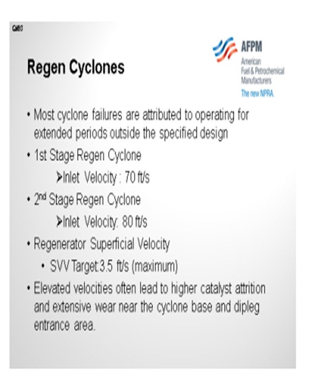
At KBR, we specify design parameters that will allow the operator to achieve extended regenerator cyclone life for several turnaround intervals. Based on our experience, it was shown that most cyclone problems are attributed to operating above the maximum recommended velocities. KBR recommends that Operations maintain a cyclone inlet velocity below 70 fps and 80 fps for the first- and second-stage cyclones respectively.
In theory, operating at these higher velocities can lead to an increase in cyclone efficiency. However, if the velocities are above the recommended values for extended periods, the unit can experience higher catalyst attrition rates and reduction in cyclone performance.
These higher velocities tend to be the primary cause for excessive wear near the base of the cone and the dipleg entrance area. Wear in this region often leads to holes and/or gases penetrating through the refractory lining and the cyclone wall itself.
A quick fix is external metal patches – or ‘boxes’, as some people call them – or an increase of refractory thickness within this area which can allow the operator to extend the life of the cyclone set if he desires to operate beyond the recommended cyclone velocity for an extended period.
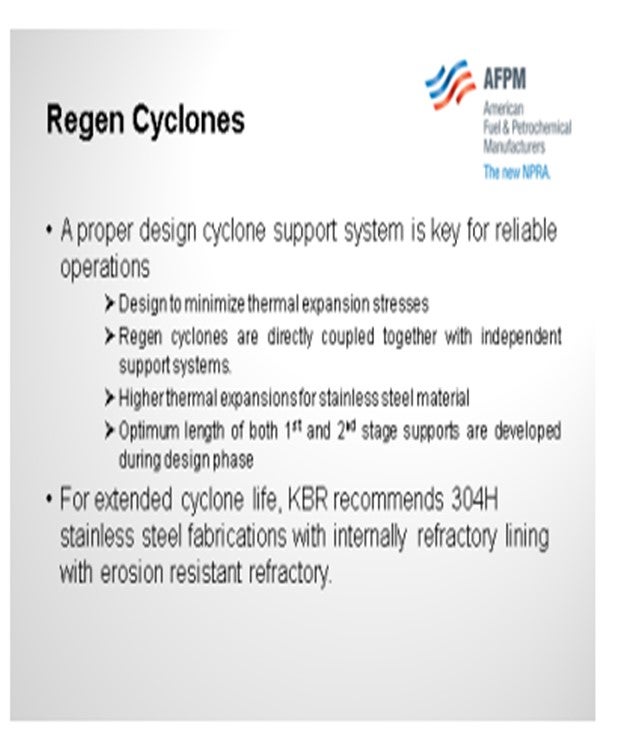
Another important design factor for the regenerator cyclones is the reliability of the support system itself. Failure to design the cyclones for minimizing thermal expansion stresses will also cause problems. Regenerator cyclones are directly coupled together with independent support systems. At elevated operating temperatures and higher thermal expansions of stainless-steel material, the regenerator cyclone supports are very critical. Therefore, it is important that the optimum length of the first stage and second-stage cyclone supports are established during the design phase.
And finally, to enhance the cyclone reliability, both cyclone sets should be fabricated with 304H stainless steel and internally refractory-lined with erosion-resistant refractory.
SCHOEPE (Phillips 66)
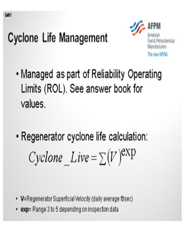
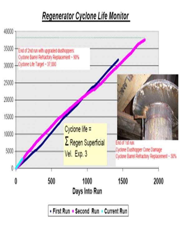
We have very similar velocity guidelines that are managed as part of our reliability operating limits. In addition, we do a monthly ‘cyclone life calculation’. There is a lot of grays on this, but it can be a useful tool to estimate the life of a cyclone that can drive changes in the refinery.
Cyclone life is a function of regenerator superficial velocity in a bubbling bed regenerator: The higher your superficial velocity, the more catalyst you will carry up to the cyclones and the faster the catalyst is going to accelerate into the cyclone and out of the cyclones, thereby increasing your erosion potential. This very simple model sums up daily averages to some exponent. The typical range for this exponent is between three and five. You use three if you have very well-built cyclones, a long cyclone L/D (length/diameter) of five, and so on. If you have old, short cyclones, you tend to use the higher number.
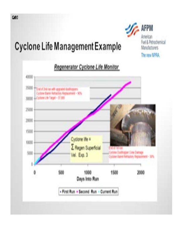
Theoretically, in an ideal world, if you had data from two runs such that when each run was ended due to cyclone failure and there were no cyclone upgrades, you could actually calibrate this exponent. But because that data is typically not available, I put together an example on the next slide which describes how we have used this model in our refinery. This unit started up in 2003. The blue line shows the sum of the daily average superficial velocity taken to the third power. At the end of that run, we saw high velocity damage: exactly the type of damage Jesse just described. If you have high gas tube outlet velocity, then the vortex extending downwards from the gas outlet tube grinds out a dust bowl. In the picture, you can see the damage on the dustbowl section. During this turnaround, we then upgraded the cyclones by installing new dust bowls that were longer and which had thicker refractory on the inside. All cyclone vendors now offer that as an option.
After the end of the first run, the unit capacity was increased by 15%. The slope of the cyclone life calculation line was much steeper. We changed the unit operation by increasing pressure, thus reducing the regenerator superficial velocity and enabling us to complete a five-year run.
You are very unlikely to reduce feed rate because of this kind of data. At the end of the second run, we had to replace 90% of the refractory. That data point is now our “end of cyclone life”. The light blue line shows our current operations.
DR. PAUL DIDDAMS (Johnson Matthey Intercat)
Is anyone using oxygen enrichment as a way of reducing superficial velocity in the regenerator to extend cyclone life?
JACK OLESEN (Praxair, Inc.)
Yes, this has been practiced in several FCC units with which I am familiar.
BROOKS (BP Refining)
I will talk more about this later, although not very much more in-depth. We actually have quite a few FCCUs with oxygen enrichment; and as I said, those sites do use oxygen enrichment to maintain a superficial velocity. We use calculations similar to what Phillips 66 uses, and we track those calculations to target our cyclone life to be in line with our inspection data. We use oxygen enrichment specifically to keep our superficial velocity down.
WILLIAMS (KBR)
At KBR, we specify design parameters that will allow the operator to achieve extended regenerator cyclone life for several turnaround intervals. Our experience has shown that most cyclone problems are attributed to operating above the maximum recommended velocity. KBR recommends that operations maintain a cyclone inlet velocity below 70 fps and 80 fps for the first- and second-stage cyclones respectively.
In theory, operating at higher velocities can lead to increase cyclone efficiencies. However, if velocities are increased above the recommended values for extended periods, the unit can experience higher catalyst attritions rates and a reduction in cyclone performance. In addition, higher velocities tend to be the primary cause for excessive wear near the base of the cone and dipleg entrance area. Wear in this region often leads to holes and gases penetrating through the refractory lining and cyclone wall. External metal patches (boxes) or increased refractory thickness within this area can allow the operator to extend the life of the cyclone set if it is desired to operate beyond the recommended cyclone velocity.
Another important design factor for regenerator cyclone's reliability is the support system. Failure to design the cyclones to minimize thermal expansion stresses will cause problems. Regenerator cyclones are directly coupled together with independent support systems. At elevated operating temperatures and higher thermal expansion of stainless-steel material, the regenerator cyclone supports are very critical. Therefore, it important that the optimum length of the first-stage cyclone supports, and the second-stage cyclone supports are established during the design phase. Finally, to enhance cyclone reliability both cyclones' sets should be fabricated with 304H stainless steel and internally refractory lined with erosion resistant refractory.
SCHOEPE (Phillips 66)
Cyclone inlet and outlet velocity and regenerator superficial velocity limits are managed as part of the Reliability Operating Limits (ROL) monitoring program. Typical values are as follows:
Regenerator:
Maximum first-stage cyclone inlet velocity:
~70 fps Maximum first-stage outlet velocity:
~75 fps Maximum second-stage inlet velocity:
~85 fps Maximum second-stage outlet velocity:
~140 fps Maximum regenerator superficial velocity (bubbling bed regenerator): ~3.4 fps
Reactor:
Maximum first-stage cyclone inlet velocity:
~70 fps Maximum first-stage outlet velocity:
~75 fps Maximum second-stage inlet velocity:
~85 fps Maximum second-stage outlet velocity: ~110 fps
These limits are, however, adjusted to individual units based on inspection history.
For second-stage regenerator cyclones, a cyclone life calculation is often done. This simple mathematical model applies to negative pressure cyclones and needs to be calibrated using historic inspection data. Since cyclone life is proportional to gas velocity and catalyst loading, regenerator superficial velocity is used to calculate a “cyclone life number”. As the regenerator superficial velocity increases, the gas and catalyst load into the cyclones increases and vice versa.
For a rigorous calibration of the exponent, data from at least two runs that ended in cyclone failure has to be available. The cyclone repair at the end of these runs cannot include cyclone upgrades. Often, there is not enough data available for such a detailed calibration. The example below shows how a value for cyclone life can be established.
Example: The newest Phillips 66 FCC unit started up in 2003. After the first run in 2007, high velocity cyclone damage was discovered on the second-stage regenerator cyclones. All cyclones had thinning and holes on the dust hopper cone outlet. In addition to this damage, about 30% of the refractory in the cyclone barrels had to be replaced. The damaged dust hoppers were replaced with longer dust hoppers with thicker refractory. Five years later at the end of the second run, about 90% of the refractory in one of the six second-stage cyclones barrel/main cone area had to be replaced. The new dustbowl design did not show any sign of catalyst erosion after five years of operation. Given the level of damage in this cyclone, the “cyclone life number” for this unit is about 37,000 using an exponent of three.
BROOKS (BP Refining)
BP uses cumulative velocity calculations for estimating our cyclone life also. Our calculations are similar to those described by Phillips 66 and are correlated to historical inspections on each unit. Some of our units that track this calculation will use oxygen enrichment if available to maintain operations within the superficial velocity targets based on this calculation.