Question 87: What is typical light cycle oil/fractionator bottoms distillation overlaps, and what can be done to improve separations to increase LCO recovery?
LALL (UOP, A Honeywell Company)
The distillation overlap of LCO bottoms product varies somewhat. In our experience, it is in the range of 20ºF to 60ºF. We also have a few units that report distillation overlaps. Most main fractionators are not designed with the objective of providing good fractionation between the LCO and bottoms section due to the existence of insufficient trays. The bottoms design is determined by the heat recovery considerations of the fractionator.
Fractionation qualities are a function of the reflux between the LCO and bottoms section. If the reflux is excessive, then less bottoms heat recovery is achieved.
LCO recovery can be optimized by the use of a bottoms quench. The quench is directly injected into the bottom of the fractionator to prevent coking. As the LCO product draw is increased, the bubble point of the bottom's material increases. The LCO draw rate should never be too high to allow the bottoms material to become unstable.
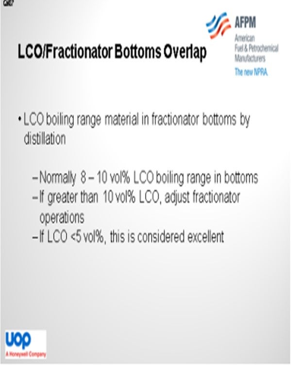
Now I am going to refer to the slide. For a typical FCC main column operation, the LCO boiling range material in the slurry product is roughly 8 vol% (volume percent) to 10 vol% by distillation. If the LCO boiling range material is greater than 10 vol% based on distillation, then an adjustment should be made to the main column operation to achieve higher LCO recovery. Having less than 5% of the LCO material in the slurry product would be considered excellent. Other options utilized by UOP are bottom sidecut strippers using steam and vacuum flushers to maximize LCO recovery.
PIMENTEL (CITGO Petroleum Corporation)
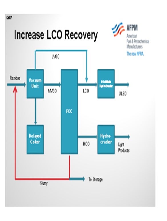
In one of our refineries, we put together an operating scheme to maximize LCO recovery, as shown on the slide. First, we have a sidecut, from the fractionator, of heavy cycle oil that is produced with a cutpoint of 800ºF as hydrocracker feed. Even so, our slurry still has more than 10% diesel-type material.
To enhance recovery, we have reprocessed the slurry back into a vacuum column along with the resid. Slurry oil has a very high boil-up rate in the vacuum column; about 80% to 90% goes out with the distillates. Most of the LCO is recovered as light vacuum gas oil and goes straight to our distillate hydrotreater to produce ULSD.
There is some internal recycle of the 800ºF to 900ºF type of material that will go back to the FCC as medium vacuum gas oil. Of course, the heavy portion of the slurry will go to the delayed coker. With this operating scheme, we can achieve a very high LCO recovery at the expense of some vacuum and FCC capacity. We do not recommend going to 100% recovery because of the possibility of accumulating PNAs in the recycle loop, so we still recommend having some slipstream of slurry as a product.
BROOKS (BP Refining)
Our experience is similar to that of the panel. We have seen a wide range of LCO to bottoms overlaps. Our recommendations fall in line with what Jag mentioned around improving your separation or using the external stripper to recover some of the LCO and reprocess.
PIMENTEL (CITGO Petroleum Corporation)
I know you do not have heavy cycle oil in Solomon.
KEVIN PROOPS (Solomon Associates)
Sergio, how long have you been doing this scheme?
PIMENTEL (CITGO Petroleum Corporation)
For several years.
KEVIN PROOPS (Solomon Associates)
Have you seen any erosion increase in the vacuum unit, especially in the transfer line to the vacuum tower?
PIMENTEL (CITGO Petroleum Corporation)
Good question. No. In fact, the main problem we have had with this occurred at the beginning when we used some flushing oil pumps to perform the recycle. They were not rated for the erosive catalyst fines of the slurry, so we damaged a couple of pumps. We had to replace them with a properly designed pump for the service.
KEVIN PROOPS (Solomon Associates) Do you see any issues in the vacuum and delayed coker?
PIMENTEL (CITGO Petroleum Corporation) We do have some solids accumulation in one tank that is in between; but in the vacuum column and the coker, we have not yet found solids accumulation.
LALL (UOP, A Honeywell Company)
The LCO bottoms distillation overlap (typically 95% to 5% points) varies widely and is in the range of 20°F to 60°F. We also have some units that report distillation gaps. Most main fractionators are not designed with the objective of providing good fractionation between LCO and bottoms section as insufficient trays exist, rather heat recovery considerations from the fractionator bottoms system dictate. Typically, five trays below the LCO draw exist to the HCO pumparound section and below three further cleanup trays excluding the disc and donut section. Fractionation quality is a function of the reflux between the LCO and bottoms sections and if the reflux is excessive, less bottoms heat recovery is achieved. LCO recovery can be optimized by the use of bottoms quench. The quench is directly injected into the bottom of the fractionator from the outlet of the slurry steam generators to prevent coking and polymerization. As LCO product draw is increased, the bubble point temperature of the bottom's material increases. The LCO draw rate should never be too high to avoid the bottom materials becoming unstable and promoting asphaltene precipitation.
For a typical, good operation of FCC main columns, the main column bottoms distillation: IBP (initial boiling point) to 8% to 10% is normally LCO boiling range material. If LCO boiling range material is greater than 10 vol% from the distillation curve, then operation should be adjusted to achieve higher LCO recovery. If LCO is less than 5% in the slurry product, this can be considered as an excellent operation.
To improve separation, a reduction of slurry steam generation or bottoms pumparound heat removal is required. This will increase the column internal reflux and improve separation. Testing and impact on economics [i.e., loss of HP (high pressure) steam versus improvement in separation], however, need to be investigated. With the reduction of steam make, quench needs to be used so that the bottoms temperature does not exceed 680°F to 685°F (360°C to 363C).
In some installations, the separation may not be critical for the refiner. In these installations, LCO is added to the slurry material as cutter stock. If the refiner does not use cutter stock for the slurry, then minimizing LCO in the slurry material should be investigated as above.
A bottoms side stripper using steam and vacuum flashers have been two types of design utilized by UOP to maximize LCO recovery. Note that minimizing LCO in the slurry material will increase coking in the bottom of the fractionator and column bottoms’ heat exchangers. Therefore, good recordkeeping and monitoring trends of unit operation is critical.
PIMENTEL (CITGO Petroleum Corporation)
In our refinery, we produce HCO as a sidecut for hydrocracker feed (800°F cutpoint) which helps increase distillate recovery. Still about 25% of our slurry oil is in the diesel range (700°F minus). In order to enhance LCO recovery, we have re-processed part of the slurry oil in the vacuum column along with the ATBs (atmospheric tower bottoms) drawing. This way the LCO is recovered along with the LVGO (light vacuum gas oil) as hydrotreater feed while the middle cut (800°F to 900°F) is recycled to the FCC along with the MVGO (medium vacuum gas oil). With this operating scheme, very high distillate recovery from the slurry oil can be achieved at the expense of some capacity in the vacuum unit and the FCC.
BROOKS (BP Refining)
BP’s experiences are similar to others on the panel. We have a wide range of LCO/bottoms overlaps, some as high as 80°F. Our recommendations on options to improve this would be to consider packing the beds to improve separation and/or using an external DCO stripper to recover additional high value LCO product.