Question 85: What is the state-of-the-art design used to minimize the impact of coke in the FCCU main fractionator bottoms and remove coke from the bottoms draw and circulating circuit?
WILLIAMS (KBR)
In general, reducing fractionator bottoms coking starts with an optimum slurry system design to minimize the column residence time and bottoms temperature. We typically target around 680°F in the bottoms. This design should include the fractionator soft area, as well as the entire slurry exchangers train.
As far as the bottom of the fractionator, KBR takes two steps to mitigate the impact of coke within the bottom of the tower itself. A coke strainer is installed in the bottom outlet nozzle to retain the larger coke particles while allowing the smaller particles to exit the cat tower into the external circuit. This strainer is a vertical cylinder, slightly larger than the outlet nozzle, with holes on a square pitch extending the full height of the cylinder itself.
To enhance the coke strainer’s performance, KBR specifies a perforated hollow ring steam sparger around the coke strainer cylinder. This sparger fluffs the bottom of the columns stump to keep the smaller coke particles in suspension until they exit with the slurry liquid mixture. As far as the circulating circuit itself and its design, the slurry exchanger operations can finally occur at the velocities held below at threshold. Therefore, KBR recommends an exchanger tube design that allows the operator to obtain a slurry velocity range between 4 fps to 10 fps. To focus on the lower end of that range at two velocities below 4 fps, solids or catalysts can fall out of the solution and, over a period of time, plug the exchanger.
In addition, all exchangers within the train itself, including the steam generator or feed exchangers, should contain at least a one-inch tube diameter to prevent plugging. In some cases, we have to address the coking conditions within the exchanger train. KBR recommends two 60% parallel design configurations for each exchanger within the train. This additional capacity provides flexibility within the system in the event that one exchanger is taken out for cleaning while maintaining feed rate only requiring a slight reduction of feed rates while the cleaning process takes place.
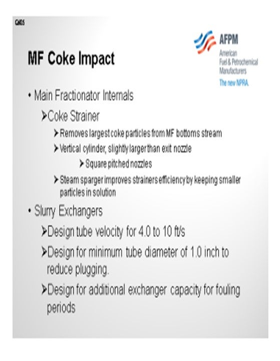
To monitor the slurry performance, KBR installs differential pressure measurements across the duplex filters and tube side of the exchanger train. Both indications are routed to the DCS with a calculated heat transfer coefficient for each exchanger to signal the operator that the system is potentially starting plug. For cleaning and periodic removal of the coke itself removal, KBR recommends the use of the duplex filters I mentioned earlier to remove the large particles that exit the fractionator bottom outlet nozzle. As mentioned, the DPIs (differential pressure indicators) are the key indicators to advise Operations when to clean these filters. Here, instruments the filters have to be isolated, flushed, steamed, depressured, and cooled prior to coke removal. To address the fouling exchanger, one must isolate flush and typically hydroblast the tubes for coke removal.
SCHOEPE (Phillips 66)
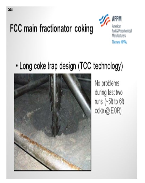
I decided to add this example because it was unique. One of our units replaced a TCC (thermo for catalytic cracking) unit. Based on TCC catalyst carryover incidences, they developed a very unique coke trap. Our coke trap is close to 10 feet long. During the last two runs, we accumulated anywhere from four to six feet of coke in this main fractionator, but we never knew about it until we actually shut down. It almost seems to be a self-limiting problem because as you build up the coke, you decrease your slurry pool residence time; and then, you stop coking. In any case, in my opinion, there is really no drawback to designing a very long coke trap.
.
LALL (UOP, A Honeywell Company)
Jesse covered this very well. My comment is that UOP has now made it a practice to take the next slurry product from the bottom of the pump discharge header at the end of that header in an attempt to clear out the bottom circuit of coke and fines and aid in the preferential removal of bits out of the system.
AVERY (Albemarle Corporation)
Coke traps are used on the outlet nozzle at the bottom of the main column to prevent large pieces of debris or coke that may have spalled from the tower during an unplanned short feed outage/shutdown from plugging the main column bottoms piping, valves, or pump strainers. Coke traps can be slotted pipes or birdcages designed such that the open area is equivalent to the outlet nozzle cross-sectional area (no pressure drop). All FCC main columns should have some kind of device in place as coke formation will occur in the bottom part of the tower.
LALL (UOP, A Honeywell Company)
The tendency for slurry oil in the main fractionator bottoms to form excessive amounts of coke is a function of residence time, composition, and temperature. Minimizing coke in the main fractionator bottoms requires proper design and operation of the process variables.
The higher the residence time of the slurry oil in the system, the greater the potential for coke formation. The residence time of slurry oil in the bottom of the main fractionator is simply the volumetric inventory of the bottoms circuit divided by the net slurry product flow rate. The bottoms inventory includes the volume of the fractionator bottoms, slurry exchangers and all associated piping. However, once the unit is constructed the inventory volume is essentially fixed and the only variable available to reduce residence time is lowering of the liquid level in the fractionator bottom which is typically a small fraction of the overall volume.
Keep in mind that temperature affects the rate of coke formation. The hottest section of the system is the counter-current contacting region of the disc and donut trays where the cooled slurry pumparound returned to the main column, de-superheats the entering reactor vapors. Within this zone, it is important to supply enough cooled slurry pumparound flow to provide proper de-superheating while maintaining a wetted surface on all of the trays. Improper contacting and localized drying of the trays can result in hot spots which increase fouling and coke deposition. To ensure proper tray wetting and de-superheating of the inlet reactor vapors, the total slurry pumparound circulation rate is designed to be the greater of either 150% of the design feed rate or 6.0 gpm/ft2 (the equivalent metric unit in cubic meters per hour per square meter equals 14.7 m3 /hr/m2 ) based on the column cross-sectional area.
Increased circulation also reduces the amount of time that the slurry oil sits inside of the fractionators which is the hottest environment of the slurry oil system. Increasing the pumparound rate decreases the mean average temperature of the slurry oil providing some decrease in coke deposition. The less time that material spends in the hottest section of the system, the lower the tendency to form coke.
In general, UOP recommends an initial maximum bottoms temperature of 655°F (345°C) for highly paraffinic feedstocks and 690°F (366°C) for highly aromatic feedstocks. Highly paraffinic feedstocks are typically characterized as having UOP K values ≥12.0 and highly aromatic feedstocks are typically characterized as having UOP K values ≤11.5. These general values are very empirical. The bottoms temperature limit for the main fractionator, however, needs to be confirmed through actual operating experience. Note that these temperature values are without quench recycle. Quench will sub-cool the bottom of the column directionally reducing the tendency to form coke by providing a cooler environment. It is important to note here that the quench is injected directly to the bottom of the column via a distributor to ensure good distribution of cooled slurry and mixing with the hot bottoms to avoid localized pockets of hot liquid.
When using quench, it is very important to constantly monitor the composition of the material. Each refiner needs to identify through trial and error, the maximum bubble point of the material prior to excessive coking. In monitoring the composition of the bottoms material through temperature, it is also important to consider the operating pressure of the main fractionator flash zone. The bottoms temperature will increase with pressure for a bubble point liquid of constant composition. Any temperature excursion in the bottom circuit has the potential to cause thermal cracking of the bottoms material and formation of coke deposits. This risk is compounded if the bottoms material is already near the stability limit for coking.
The second part of the question deals with the removal of coke from the bottoms system. A coke trap with typically 150 mm (millimeters) x 100 mm openings is located over the bottom outlet to prevent large pieces of coke or other debris from entering the bottom line and causing blockages in downstream circuit. Parallel coke strainers are provided at the inlet of the slurry circulation pumps allowing smaller coke chips and catalyst fines to pass through while, very importantly, retaining larger pieces of coke which have passed through the coke trap in the fractionator bottom and can be damaging to the circulation pumps. The coke strainer is a basket offset-type with side entry and bottom exit to avoid accumulation of catalyst fines in the basket strainer body. Finally, UOP has made it a practice to take the net slurry product from the bottom of the pump discharge header at the end in an attempt to clear the bottoms circuit of coke or fines aiding preferential removal of bits out of the system.
WILLIAMS (KBR)
In general, minimizing fractionator bottoms coking starts with an optimum slurry system designed to minimize column residence time and bottoms temperatures (typically below 680ºF). This design should include the fractionator sump area, as well as the entire slurry exchanger train.
KBR takes two steps to mitigate the impact of coke within the bottom of the fractionator. A “coke strainer” is installed on the bottoms outlet nozzle to retain the larger coke particles while allowing smaller particles to enter the external circuit. This strainer is a vertical cylinder slightly larger than the outlet nozzle with holes on a square pitch extending the full height of the cylinder. To enhance the coke strainer performance, KBR specifies a perforated halo ring steam sparger around the coke strainer cylinder. The sparger fluffs the bottom of the column sump to keep the smaller coke particles in suspension until they exit with the slurry liquid mixture.
As for slurry exchangers operations, fouling can occur if velocities are held below a threshold. KBR recommends an exchanger tube design that allows the operator to obtain a slurry velocity range between 4.0 fps and 10.0 fps. At tube velocities below 4.0 fps, solids (catalyst) fall out of solution and over a period of time will plug the exchangers. All exchangers (steam generator and feed/bottom exchangers) within the system should contain at least a one-inch tube diameter to prevent plugging. Measured tube side differential pressures and calculated heat transfer coefficients over time are the best methods for identifying potential coking within the heat exchanger train.
Also, to address coking conditions within the exchanger train, KBR recommends two 60% parallel design configurations for exchanger trains. This additional capacity provides flexibility within the system in the event one exchanger is taken out of service for cleaning.
For periodical coke removal, KBR recommends the use of duplex filters to remove large coke particles that exit the fractionator bottom outlet nozzle. Differential pressure indicators are key indicators to advise operations when to clean each filter. To address a fouling exchanger one must isolate, flush and hydroblast tubes for coke removal.