Question 81: Under what conditions is iron on FCC catalyst mobile, and how does this affect catalyst performance?
DE GRAAF (Johnson Matthey Process Technologies)
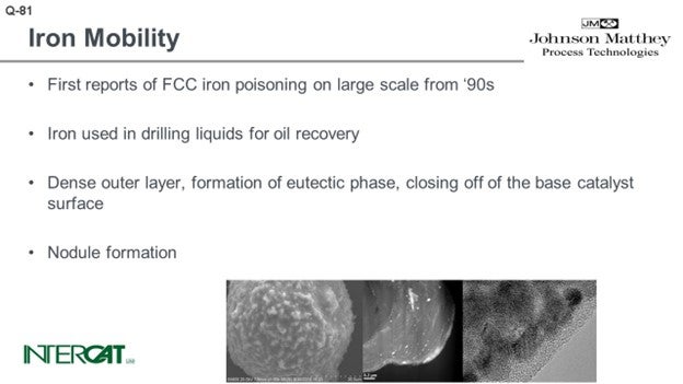
I think that the last statement from the floor was an excellent introduction to this question about iron mobility. Surprisingly, I was the only one on the panel who was willing to take this question; but I do expect some reaction from the floor hereafter. The first reports from iron poisoning come mainly from the 1990s. Iron was used in drilling liquids for oil recovery. What happened in a couple of units is that when the iron on the catalyst increased, you would see a decrease in ABD and an increase in slurry yield because the outer surface was completely closed off. You can see that because of the drop in ABD, there was some erratic catalyst circulation. And frequently, you can see an increase in SOx emissions because iron on the catalyst acts as a sort of inverse SOx additive. It reacts with H2S in the riser, drags it to the regenerator, and oxidizes down to SOx.
There are a lot of papers out there and many beautiful pictures, like the sort of Death Star shown in the bottom left-hand picture. You can see that the catalyst is covered with nodules. The nodules typically contain an iron top. The glassified outer surface of the catalyst is about 0.50 microns and can be up to 3 microns. When you look into that outer layer, you see a lot of very small magnetite iron oxide crystals. The problem is not so much iron on catalyst as it is the amount of added iron from the feed. When you study iron-poisoned catalysts with transmission electron microscopy, you see the iron present in small crystals. The crystals form agglomerates of about 10 to 30 nanometers, and they tend to cluster at the outer surface of the catalyst. That outer surface of the catalyst is eutectic.
The problem with iron – even at level of, say, 0.3 wt% added iron – is that all of the added iron is present at the outer surface, which means that the concentration of iron at the outer surface can be quite high: easily be 4 or 5 wt%. It is concentrated and causes a eutectic to form. When you see that nickel or copper touch upon the catalyst or deposit on the catalyst, there can be interaction with alumina. The nickel or copper form nickel aluminate or copper aluminate and have a very good chemical bond at the base catalyst; vanadium, less so. Iron oxide also has no affinity with any component on the base catalyst. So, what you see is a sort of soup of silica with iron oxides floating in it.
So on one hand, what determines metal mobility and what is the affinity of the metal to bind with the base catalyst? On the other hand, what is the possibility for transfer? If you have a sticky outer surface in the FCC, you will have multiple particle-to-particle collisions. By particle-to-particle collisions, as we have a sticky surface, you will observe the transfer of some of the crystallites of those iron crystallites. We used scanned electron microscopy to look into hundreds of particles, and we did population studies. If a metal has infinite diffusivity, it can diffuse up to the speed of light from particle to particle in an FCC unit. What you would expect is that every particle would have the same concentration. Vanadium has a low affinity for binding to an FCC catalyst particle. What you see at the bottom left-hand side graph is a Gaussian distribution of vanadium and distribution of the particles.
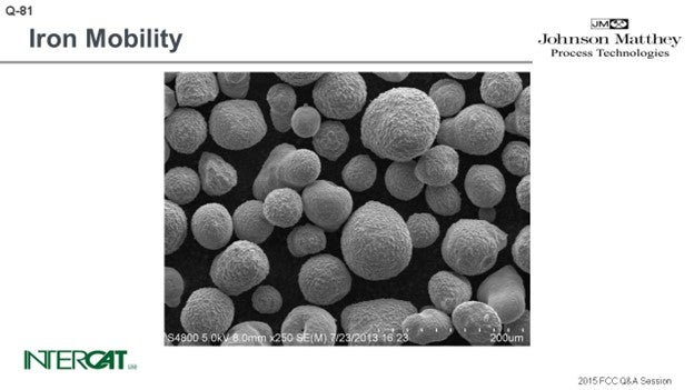
At first, we were also very surprised to see that in every case of iron poisoning we observed, the iron had a similar Gaussian distribution curve. In hindsight, we were not so surprised looking into the mechanism of how iron migrates and the affinity of iron to bind one particle because the affinity is just not there. We did some laboratory experiments and investigated whether we could mimic what happens in a unit suffering from iron poisoning. Under mild steaming conditions, we saw that there is migration happening when you steam the iron-poisoned catalyst. If you take 75% of this iron-poisoned catalyst and 25% inert, by using a moderately mild steaming protocol, we can show migration of iron to the inert particles. Under severe steam protocol, we got the result you see on the slide. We saw a transfer of iron and formations of nodules on inert that initially did not have any iron on it.
KENNETH BRUNO (Albemarle Corporation)
Indeed, this is a very challenging and complex story and situation, and in fact, contentious. As Adam said earlier in response to the previous question, the source of iron is critical: whether it is inorganic or organic. Organic iron will be the more harmful of the two.
Regarding mobility, our results are different than what Bart (Johnson-Matthey) described. We have seen some evidence of mobility, but we feel it is largely mechanical mobility; analogous to dust particles interacting, for example. However, we have found no conclusive evidence of what we call atomic mobility. Even maybe more importantly, we have studied many cases and have no conclusive evidence of iron preferentially adhering to a specific catalyst or additive particle.
Question 80 actually referred to accessibility or diffusion being important. And of course, we agree. There was also a comment about the importance of pore architecture. Of course, pore architecture is important. But when you are dealing with iron, the surface accessibility or surface architecture is even more critical.
So, with those points, again, the effect of Fe is a very challenging and complex problem. There are many different and competing thoughts on this topic. We have more data and details provided in the Answer Book. So again, we encourage you to consult the Answer Book. Thank you.
DE GRAAF (Johnson Matthey Process Technologies)
In response to Ken’s comment, the inert we used in this question is a silica/alumina-based inert. It was clay sprayed. It did not contain a metal trap. So, what we observed here was a transfer of nodules of iron from an iron-poisoned catalyst to a completely inert particle and formation of nodules on the clay particle.
MELISSA CLOUGH (BASF Corporation)
You might have seen the article that was published today in the AFPM Daily. I will just talk about a couple of points. BASF has also looked at iron mobility and the effects of iron. We are working with a number of refiners here in the States, and we are also looking at units in Asia and Europe. We evaluated it in a number of ways. First, we used scanning electron microscopy. We have also done separations and looked at the iron in the different fractions. Another technique is literally using a magnet and pickup catalyst with high iron to leave the low iron behind.
We then compared the iron distribution in the different fractions as shown by the three methods. In most cases, we see that iron mobility is very different than that of nickel and vanadium, and we definitely do not see very high mobility. I included some numbers in the article, but just in qualitative words. The mobility we have seen is more similar to nickel than to vanadium.
DE GRAAF (Johnson Matthey Process Technologies)
We have done similar experiments, including sink/float experiments. We typically see that in old layers, there is a similar amount of iron present. When you study these catalyst fractions with electron microscopy, you see every layer has a Gaussian distribution present again. So even though the amount of iron per layer is fairly constant for every fraction of the sink/float, we have observed a Gaussian distribution of metals.
RAMA RAO MARRI (CB&I Lummus Technology)
So far, I think we have discussed mostly the catalyst solutions. Thank you all for contributing information about the catalyst, but another aspect is the hardware. The ultimate effect of the iron, mainly when it is a change of the feed out of crude slate to the refinery, is the increase in the bed temperature. That is the fundamental change. So, when it changes, the dense-bed temperature catalyst reduces, and conversion is affected.
An option we adopted in one of the refineries that experienced this situation was to implement a long-term solution to further our technology from changing out the disc condoner. This is typical technology that helped them to ease out the increase in resid bed temperature. It also helped increase the catalyst issued and carried out the conversion loss. So, this is one of the catalyst solutions that can be considered.
BART DE GRAAF (Johnson Matthey Process Technologies)
The first reports of FCC iron poisoning on a large-scale date from the 1990s. Iron was used in drilling liquids for oil recovery. Iron poisoning results in a loss of activity and an increase in slurry yield. The apparent bulk density of the catalyst decreases, which causes a drop in pressure differential over the standpipes and can lead to erratic catalyst circulation.
The effect of iron poisoning has been highlighted in many papers including electron micrographs of FCC particles covered with nodules. The pictures show further a dense outer layer due to the formation of a eutectic phase. This dense outer layer closes off the base catalyst surface.
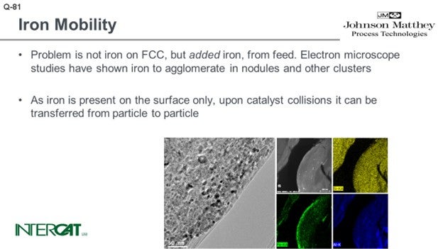
The iron in the FCC catalyst itself is not the problem, but added iron is iron from feed. Even at levels of 0.3 wt% added iron, some catalysts are already poisoned by iron. The 0.3 wt% is very unevenly distributed over the catalyst; all the added iron is at the catalyst surface where it easily reaches 4 wt% and is enough to create the eutectic dense surface layer.
Iron from feed is deposited as single atoms on the base catalyst. Electron microscope studies have shown iron to agglomerate in nodules (caps of nodules typically consist of iron oxide) and other iron oxide clusters. These iron oxide clusters show that iron atoms are mobile on the catalyst surface. Added iron oxide is only present in the dense outer layer of the particle; it does not diffuse deeper into the FCC catalyst particle. The outer surface is somewhat sticky because of the eutectic. As iron is present on the surface only, upon catalyst collisions, it can be transferred from particle to particle.
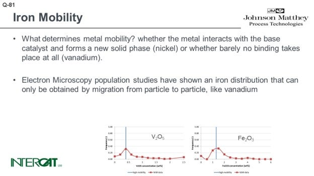
What determines metal mobility? Metal mobility is determined by the possibility of the metal interacting with the base catalyst and whether it can form a new solid phase (nickel) or whether barely any binding takes place at all (vanadium). Iron oxide does not bind to any base catalyst component.
Electron microscopy population studies have shown an iron distribution that can only be obtained by migration from particle to particle, like vanadium. These results have been obtained by studying several hundreds of e-cat particles and comparing their average metal concentration on particles. As iron distribution due to its agglomeration is very uneven over catalyst particles, it is essential to study average concentrations per particle and compare average concentration per particle versus the number of particles with this concentration. As comparison, in order to study whether the flue is contagious, it will be more relevant to establish the core temperature of 5,000 people than to study one person and measure this person’s temperature at 5,000 different spots.
KENNETH BRYDEN and SHANKHAMALA KUNDU (Grace Catalysts Technologies)
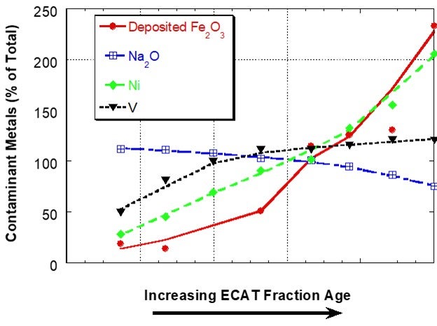
Iron (Fe) is present in FCC catalyst as an element in the clay used in manufacture. Hence, the iron content of the fresh catalyst is dependent on the clay source and clay content of the catalyst and will vary from supplier to supplier and catalyst to catalyst. Additional iron comes into the FCC unit from contaminants in the feed and this additional iron can have adverse effects on catalyst performance when it results in an iron-rich glassy shell on the surface of catalyst. The shell inhibits diffusion thereby lowering conversion and increasing slurry yield18. One of the first descriptive scientific publications on the subject of iron mobility was the Grace paper “Mechanism of Cracking Catalysts Deactivation by Fe,” that was published in 2004 in Volume 149 of Studies in Surface Science and Catalysis19. In this paper, sink/float density separation was used to separate equilibrium catalyst into different age fractions. For a unit with a low to moderate amount of deposited iron, the iron showed a sharp, non-uniform distribution with catalyst age, suggesting that the iron had much lower mobility than V and Na in the unit and that iron mobility was similar to Ni (Figure 1).
Figure 1. Distribution of Fe, Na, Ni and V on e-cat fractions from a unit with low to moderate amounts of Fe separated by a sink/float method. Fe on e-cat was 0.74 wt% Fe2O3. In this case, Fe and Ni content of e-cat increases sharply with age indicating that the two contaminants are not mobile. Na and V content of e-cat does not change as much with age, suggesting increased mobility.
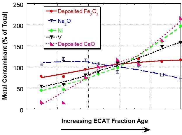
However, for a unit with a very high level of deposited iron, the iron distribution was relatively uniform between the different age fractions, suggesting that the interparticle mobility of iron was the same or higher than the vanadium mobility (Figure 2). In sink/float analysis of e-cat from additional units, Grace has found that iron can be mobile in some units and for those units the iron mobility is typically of the same magnitude as vanadium mobility.
Figure 2. Distribution of Fe, Ca, Na, Ni and V on e-cat fractions from a unit with high amounts of deposited Fe separated by a sink/float method. Fe and Ca levels on e-cat were 1.91wt% Fe2O3 and 0.15wt% CaO (calcium oxide). In this case, the iron is relatively uniformly distributed among particles of different ages, suggesting mobility.
In laboratory experiments where iron rich e-cat is steamed with fresh catalyst without depositing iron, we have found that some iron migration can occur to the fresh catalyst. The level of iron transfer increased with increasing steaming temperature and increasing contaminant iron level. In these experiments, we did not observe any reduction in the iron nodules present on the iron-enriched e-cat, and no nodule formation was observed on the fresh catalyst.
What is not fully understood is how iron moves from particle to particle within a unit and if this movement has any effect on catalyst performance. Detailed SEM and EPMA (electron probe microanalysis) analysis of e-cat particles has found that deposited iron is always on the exterior surface of the particle and is not present in the interior of the catalyst particle. This suggests that iron does not migrate within an individual particle. If the iron transfer was via a gas-phase diffusion process, it would be expected to also move within an individual particle, which is not observed. The most likely means of iron mobility is physical transfer upon particle/particle contact. In the 2004 “Studies in Surface Science and Catalysis” paper, Grace noted that deposited iron in a unit comes from different sources (organic iron, finely dispersed sub-micron colloidal iron, and iron particulates) and that iron migration may be due to loosely attached iron rich dust migrating from particle to particle. It may be that the iron species which can move from particle to particle in a unit are not the same iron species which are responsible for the nodule formation on the surface of e-cat. The mechanism of iron migration in a unit is an area of ongoing study. Iron migration appears to be dependent on unit conditions and the types of iron present in the feed.
To manage iron poisoning, refiners should reformulate to more iron-resistant catalysts and consider higher fresh catalyst additions. Catalyst design can be optimized to resist the effect of contaminant iron and calcium. High alumina catalyst, especially catalyst with alumina-based binders and matrices, such as Grace’s MIDAS® and ACHIEVE® catalyst families, are best suited to process iron- and calcium-containing feeds because they are more resistant to the formation of low-melting-point phases that permanently destroy the surface pore structure. Optimum distribution of mesoporosity (pores in the 100 to 600 Å size range) also plays a role in maintaining performance because diffusion to active sites remains unhindered, even with high levels of contaminant metals. The resistance of MIDAS® and ACHIEVE® FCC catalysts to iron and calcium poisoning has been demonstrated in numerous commercial applications20,21,22.
Some refiners also consider the use of flushing e-cat to temper Fe poisoning. This strategy can help limit the effect of Fe on fresh catalyst but comes with several caveats. One must make sure the e-cat in use is not contaminated with Fe (Fe poisoning can occur at levels as low as 0.2 wt% added Fe); additionally, the quality of the e-cat may require a change to the fresh catalyst strategy (either formulation or addition rates) to maintain desired unit performance.
In summary, iron can be mobile in an FCC unit, but it is unclear how iron mobility affects catalyst performance. Not all of the factors influencing iron mobility are understood, but it appears to depend on iron concentration, temperature, and the types of iron contaminants present in the FCC feed.
MELISSA CLOUGH (BASF Corporation)
When looking at iron mobility, or any metal mobility for that matter, it is important to differentiate between intraparticle mobility (within a single catalyst particle) and interparticle mobility (from particle to particle). It is also important to understand that the answer is usually not a clear “yes” or “no”; as with all FCC questions, it depends. So, trying to quantify the answer is more important than a “yes” or “no”. Looking at intraparticle mobility, we can quantify this type of mobility by using scanning electron microscopy (SEM) data of cross-sectional areas of catalyst particles. Comparing the amount of contaminant metal on the outside versus on the inside gives us a Peripheral Deposition Index (PDI).23 For context, vanadium typically has PDI values of approximately 1 indicating close to uniform content of vanadium throughout the particle and thus high intraparticle mobility. We have seen iron PDI values ranging from 4 to over 7, indicating low intraparticle mobility and similar to the deposition profile of nickel. For interparticle mobility, we can use a variety of techniques to study bulk e-cat. Metals analysis of sink-float separated catalyst particles (where fractions are separated based on age) shows a standard deviation among fractions for iron being between those of vanadium (high mobility) and nickel (low mobility). Looking at bulk e-cat in SEM, you can clearly see a distinction between new (no iron) and old (iron) catalyst particles via nodulation and surface mapping, indicating that the mobility profile of iron is distinctly different than that of vanadium. In summary, across a number of commercial units studied, iron does not show high mobility like vanadium. Its mobility is low and closer to that of nickel.
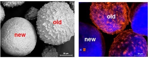
Left: SEM morphology of a new and old catalyst particle, differentiated by iron nodulation
Right: SEM surface mapping (alumina in blue; iron in red) of old and new catalyst particles
Units with iron-poisoned catalysts can face a number of concerns either from the chemical or physical effects of added iron. The chemical effects are often minor and include higher hydrogen and coke due to the dehydrogenation activity of iron, mild CO promotion, and the transfer of sulfur from the reactor to the regenerator, which can increase SOx emissions. The physical effects include nodule formation, which can impact catalyst circulation and vitrification, which can reduce surface area. Severe poising leading to surface blockages is the most common concern. Surface blockage can cause a drop in conversion with increasing added iron, leading to higher slurry yields. The amount of iron that causes significant surface blockage to result in a loss of conversion is another “It depends” answer and depends heavily on the type of catalyst. Catalysts with optimized porosity, especially surface porosity, give improved iron tolerance. BASF practices in-situ manufacturing (as opposed to incorporated manufacturing) which has been shown to have improved iron tolerance (BASF survey completed in 2001). Based on surface morphology, in-situ manufactured catalysts have high surface porosity which can withstand a higher degree of fouling due to iron. BASF catalysts have been successfully used commercially with above 2 wt% e-cat total iron, or 1.5% added iron.
GEORGE YALURIS, KENNETH BRUNO, and RYAN NICKELL (Albemarle Corporation)
Iron is a contaminant metal often found in the FCC feed and can be either organic or inorganic in origin. As the feed evaporates and cracks, iron deposits on the catalyst. Only organic iron – either molecular or colloidal – significantly reacts with catalyst components such as silica and other feed contaminants such as calcium and sodium, forming eutectic phases which sinter and destroy the surface porosity of the catalyst. As the surface pores begin to close, the large feed molecules encounter increased diffusional resistance to access the catalyst’s interior. The catalyst particles get encapsulated by the formation of a vitrified, low-porosity, iron-rich ring (an egg-shell formation) and lose their ability to absorb, evaporate, process, and crack feed molecules. The result is reduced bottoms upgrading and conversion.
As the surface structure is destroyed, the catalyst becomes nodulated (which causes a decrease in the ABD). The iron ring typically penetrates no more than 5 m deep into the particle. If iron were atomically mobile, it could easily penetrate inside the catalyst particles and get dispersed to much lower concentrations, and we would not observe an iron ring around the catalyst particles. It is therefore clear that no molecular or surface diffusion mechanism exists that enables iron mobility.
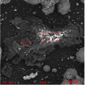
It is important to realize that iron in the FCC feed can also manifest as inorganic particulates ranging from dispersed micron sized to larger, even catalyst-size particulates. The source and composition of these particulates can vary from highly enriched iron formations (perhaps the result of corrosion and erosion of hardware) to high iron content soil/clay particulates with intricate yet decisively non-FCC catalyst shapes. We show an example of such iron-rich particulate contaminant in the below SEM/EDX chemical mapping image.
SEM image of a high-iron clay particulate found in an FCC unit
If small enough, these particulates can attach themselves to the catalyst surface. We show below an example of a larger high-iron particle attached to a catalyst particle, noting that most of the feed particulate contaminants that can attach to the catalyst particles are smaller than a few microns. This kind of particulate iron contamination may look bad in SEM images, but it actually does only minor damage, if any, to the catalyst as large portions of the exterior surface remain unaffected.
Iron particulates can break away and move from one catalyst particle to another, the same way small dust particles can move from one larger particle to another. One can also expect that as catalyst particles abrade or break into smaller ones, sections of the exterior surface rich in iron can form smaller micron-size particulates which also can move from one catalyst particle to another. In other words, iron can demonstrate “mechanical mobility”. Since these fine particles (regardless if they come with the feed or are generated by attrition mechanisms) are easily entrained, the fines of units with iron contamination are often enriched in iron; meaning, they contain more iron than the e-cat which generates them.
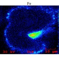
Below is an SEM/EDX chemical mapping of an FCC catalyst particle cross-section which shows a large high-Fe particulate attached to it, as well as several smaller (1 to 2 m) particulates. Areas of high iron are indicated by green, yellow, and red colors.
The mechanical transfer of iron particulates from one particle to another can appear falsely significant, since relatively fresh catalyst particles can have some iron on their exterior surface and even nodule formations like what we typically see in older iron-deactivated catalyst particles. However, as it should be apparent now, the formation of these nodules on the exterior surface of the catalyst particles is a necessary but not sufficient condition that could result in bottoms cracking and unit conversion loss. Nodules can form by organic (molecular and colloidal) and inorganic (finely dispersed and particulate) iron; yet the impact on the catalyst and unit performance can be dramatically different depending on the nature of the iron contamination. Indeed, we have seen resid cracking units where as little as 2000 ppm added iron can cause significant catalyst deactivation; while in others having added iron of 5000 ppm, there was no effect on bottoms cracking or conversion. When we investigated these units, one of the key factors we found determining the effect of iron on catalyst and unit performance was proven to be the nature of the iron in the feed.
The mechanism we described here for iron particulates moving from one particle to another is a non-specific and random mechanical process. Exhaustive investigations to date, conducted by Albemarle, have demonstrated that there is no catalyst or additive currently being used in FCC units which preferentially pick up iron. The most effective way of resisting the effects of iron contamination is by leveraging highly accessible catalysts with an alumina matrix (such as Albemarle’s ADM-20 bottoms cracking alumina). These catalysts provide the open-pore architecture with larger pore mouths on the particle surface which are harder to bridge and block. They also resist the formation of iron-silicon- calcium-sodium eutectic phases which sinter and destroy the surface pore architecture of the cracking catalyst particles.