Question 78: What inputs or trips are typically included in FCC flue gas expanders and CO (carbon monoxide) boilers' safety interlock systems? Are there any governing standards [(e.g., API and NFPA (National Fire Protection Association)] that apply?
BROOKS (BP Refining)
I would like to address this question as two different parts, beginning with the flue gas expanders. BP has three flue gas expanders in its system. These expanders are all set up with slightly different configurations. We have one FCCU flue gas expander that is directly coupled to the main air blower. We have another that is coupled to a main air blower, but this site has onsite redundant air blowers. We also have one that is just connected into the electrical grid.
We have different expander trip setups and systems and corrective actions and alarms for each of these because they do not have the same configurations. All of these systems include typical rotating equipment trips around high expander and turbine speed, high expander compressor turbine displacement, low lube oil pressure, and typical anti-surge control; so, they are all usually included in anything we would have around an expander.
As I said, we have various configurations and setups for how the flue gas expander trips the FCC. One of our flue gas expanders goes directly to the electrical grid and actually just trips to a bypass; it does not trip off the FCC. Basically, any trips for that flue gas expander are just for equipment protection. Our expander that is directly coupled to the main air blower will trip the FCC offline. It is part of the safety interlock system (SIS); because if you lose that expander, you will lose your main air blower and need to shut down your FCC.
Our expander, which is built into the one that I mentioned with redundant air blowers, actually does not go into a safety interlock system. It goes into what we call a Critical Corrective Action System which starts taking corrective action to reduce flow rates to the unit without operator intervention, cutting back the FCC automatically. The unit can then run on the other available air blowers, but it does not actually trip it off.
The critical correction action system is part of our distributed control system (DCS). The operators can turn it off if they desire. My point is that you need to consider your trip system setups for tripping off the FCC with respect to the configuration of your expander. We also include typical rotating equipment alarms, as well as all of these high-bearing temperatures and high-winding temperatures, for example, as shown on the slide.

Again, we have multiple configurations for our CO boilers. Most of our units actually run in full-burn and do not have CO boilers. We do have one unit that runs in full-burn and also has a CO boiler. We run the FCCU flue gas through it to provide additional heat and steam generation, but it runs mostly on fuel gas firing.
With that unit, we have a bypass stack; and if the CO boiler needs to trip offline, then the FCCU flue gas flow will go directly to the bypass stack. Another configuration we have is a partial-burn CO boiler that is actually going to trip into a bypass. Then we tend to bring our unit under control and come out of the bypass and back to the CO boiler. We consider that our CO boilers should fall under fired-heater standard trip conditions.
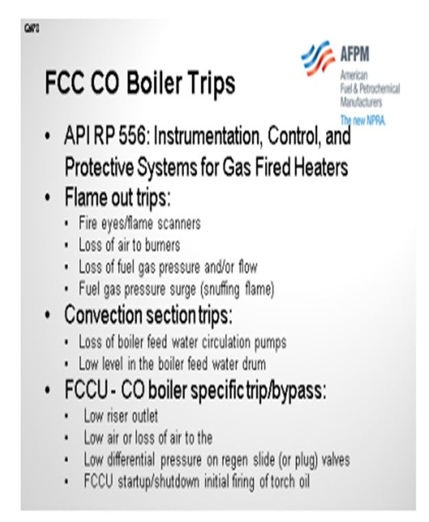
API RP 556 is a recommendation for protective systems around fired heaters. The main concern is typically going to be around flameout, so fire eyes/flame scanners usually have two-out-of-three voting systems for all of these: loss of air to the burners, loss of fuel gas pressure, and loss of fuel gas purged. Obviously, all of these are focused around preventing a fuel-rich environment in your CO boiler. With this, since it is a boiler, we also have typical convection section trips to help protect the convection section. So if you have boiler feed water going through circulation pumps, those pumps would actually trip. And then, since you have additional consideration from the flow of your flue gas through the CO boiler, you will also need to add extra controls to the CO boiler that would trip to a bypass around low FCC riser outlet temperatures, low air, or loss of air, which are typical conditions that trip off an FCC.
SCHOEPE (Phillips 66)
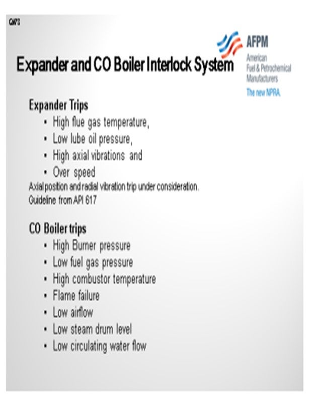
On the expander, we have very similar trips as those of BP. The expander also has an expander trip on high flue gas temperature, low lube oil pressure, high axial vibration, and overspeed. We are also, however, considering an axial position trip which will monitor the health of your thrust bearing. Also under consideration is a radial vibration trip.
The expander: Depending on the recovery train, the expander basically determines if your FCC shuts down or not. So if your air blower is directly connected to your expander and that is the only air blower, then the FCC SIS would also be activated. If you have a gen set or multiple air blowers, then the FCC would typically stay online.
CO boilers: Typically, a CO boiler trip only trips the burner; it will not trip the FCC unit. Even in resid units, they typically try to move as quickly as possible to complete combustion, and then they relight the CO boiler. The trips are listed on the slide.
LALL (UOP, A Honeywell Company)
The technical standard that UOP follows is the Functional Safety Instrumented Systems for the Process Industry Sector, which is ANSI/ISA-84.00.01-2004 [IEC 61511 Part 1 modified]. I have included the UOP strip inputs and shutdown matrix in the Answer Book
BROOKS (BP Refining)
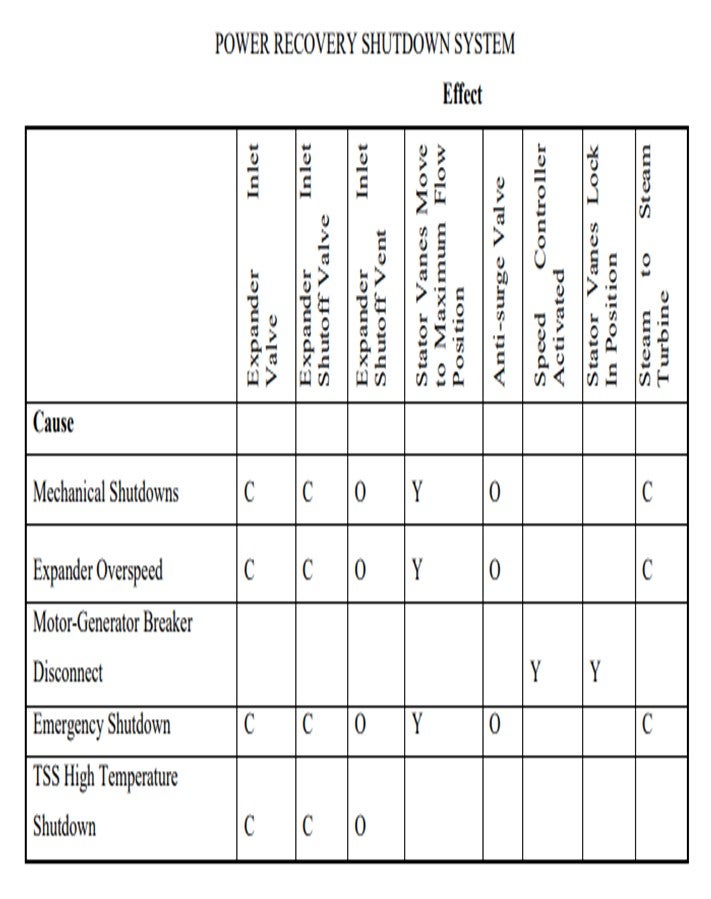
One BP unit’s expander is directly coupled to their air blower, which also has a steam “helper” turbine. The expander and motor are referred to as the power recovery train (PRT). The PRT trips on this unit are tied into the safety interlock system with an SIL-2 (safety integrity level-2) rating which results in a unit shutdown due to loss of the main air blower powered by the PRT in typical operation. The unit has developed methods to run the main air blower with the PRT offline via the “helper” steam turbine and an auxiliary air line from other refinery air compressors. The trips in this system are typically normal rotating equipment protection trips and include the following:
• high expander and turbine speed (two-out-of-three vote),
• high expander, compressor, and turbine displacement (two-out-of-three vote),
• low lube oil pressure (two-out-of-three vote), and
• compressor anti-surge controls.
In addition to the trips just mentioned, alarms to prompt operator action are included for the following:
• high bearing temperatures,
• high motor winding temperatures,
• high expander inlet temperatures,
• high expander inlet pressures, and
• low rotor cooling steam.
Another BP unit is fortunate to have multiple air blowers for its FCC complex. One of these air blowers is powered by a flue gas expander. Due to the redundancy in the air delivery system, this unit does not employ a safety interlock system with automatic trips. Instead, its critical corrective action (CCA) system is a series of automatic unit moves designed to take the unit to minimum feed and air rates but not shut down the FCCU. These minimum rate target settings are based on the capacity of the remaining air blowers in the system. The CCA includes the inputs listed above.
Our final BP expander is not coupled to an air compressor; it supplies electricity directly to the refinery energy grid. Trips around this expander include those already mentioned and result in flue gas routing around the expander via large bypass lines in the flue gas system. Systems linked to electrical grids should include a bypass trip in the event that the expander decouples from the grid to prevent excessive expander over-speed damage.
Trips should also be in place to bypass or shut down the expander on FCCU shutdown and automatic trips to protect the equipment.
The majority of the BP FCCUs operate as full-burn units without CO boilers. We have two joint venture sites that operate in partial-burn with CO boilers and one resid FCCU with a two-stage regenerator equipped with a CO boiler on the first stage flue gas outlet. None of our CO boilers are fired with fuel oil.
We have one additional site that previously ran in partial-burn and has retained its CO boiler, which is used in refinery steam generation. In this capacity, the majority of the steam is generated by firing fuel gas burners. Additional steam generation is provided by the hot FCCU flue gas running through the boiler.
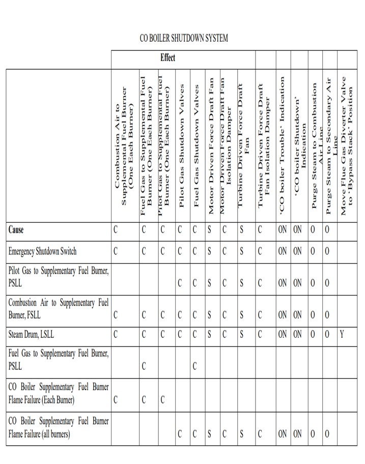
At BP, we consider a CO boiler to fall under the same safety requirements as a typical fired boiler. We have central required safety trips based on API RP 556 (Instrumentation, Control, and Protective Systems for Gas-Fired Heaters). API RP 556 does not cover CO boilers specifically, but it does include information on gas-fired heater protective systems in Section 3.4. BP specifies additional safety trip/bypass requirements for CO boilers.
For CO boilers and fired heaters, safety instrumented systems are implemented to mitigate possible hazardous explosions of fired heaters due to the accumulation of combustible material on burner flameout. Our CO boilers have fire eyes or flame scanners to detect flameout. These are included (typically based on two-out-of-three voting) in the trip/bypass instrumentation system. Fired heater burner (main and pilot) flameout can result from a number of situations, which are also included in our trip systems, such as:
• loss of air to burners,
• loss of fuel gas pressure and/or flow, and
• fuel gas pressure surge (snuffing flame).
These are boilers that generate steam in the convection section of the furnace, which has additional trips. These trips protect the convection section of the boiler from overheating and include loss of boiler feed water circulation pumps and low level in the boiler feed water drum.
Additional considerations are necessary for CO boilers as another source of combustible material is present. BP considers a CO boiler trip or bypass as necessary any time highly combustible material could be present in the flue gas. Thus, in addition to the trips for fired heaters, our CO boilers also trip, and are routed to a bypass stack, on
• low riser outlet temperature (which can lead to oil-soaked catalyst in the regenerator due to lack of feed vaporization),
• low air or loss of air to the regenerator (that can lead to a flow reversal of oil into the regenerator),
• low differential pressure on regenerated catalyst slide (or plug) valves (which can lead to a flow reversal of oil into the regenerator) [This trip does not apply to R2R regenerator designs with separate flue gas systems as a reversal would send oil to the second stage of the regenerator], and
• during any phases of FCCU start-up and shutdown that involve initial firing of torch oil (which may be unstable) to the regenerator and/or feed introduction to the riser.
Our CO boilers trip by opening valves to divert flow to a bypass stack until the upset can be resolved and brought back into control.
SCHOEPE (Phillips 66)
Expanders: Experience Layout: If an expander trip initiates the FCC oil out logic, depends on the configuration of the expander power train. Expander trains that connect the expander directly to a single main air blower can initiate a FCC trip if the expander trips. If the expander is used to generate electricity only, or if multiple air blowers are available, an expander trip does not trip the FCC oil out logic. The flue gas expanders in the Phillips 66 system trip on high flue gas temperature, low lube oil pressure, high axial vibrations, and over-speed.
Trips on axial position and radial vibration are currently under consideration. Some of these trips were developed based on guidelines from API 617 (Axial and Centrifugal Compressors and Expander-compressors for Petroleum, Chemical and Gas Industry Services).
CO boilers: CO boiler trip does typically not initiate the FCC SIS oil out logic. In case of a CO boiler trip, the FCC is typically moved from partial-burn to complete combustion as quickly as possible to remove CO from the flue gas in preparation for relighting the boiler. Moving a Resid FCC into complete combustion makes it necessary to reduce the feed to minimum. Since this operation may take several hours, some units choose to pulled feed for a short period of time to relight the CO boiler.
The burner(s) in the CO boiler will trip at the following conditions: high burner pressure, low fuel gas pressure, high combustor temperature, flame failure, low airflow, low steam drum level, and low circulating water flow.
LALL (UOP, A Honeywell Company)
The technical standard which sets out practices in the engineering of safety instrumented systems that UOP follows is ANSI/ISA-84.00.01-2004 (IEC-61511-1: Mod) – Functional Safety: Safety Instrumented Systems for the Process Industry Sector.