Question 77: For our emergency interlock system, we employ two-out-of-three voting systems for slide valve differential pressure transmitters. We use dedicated transmitter taps for each transmitter, but we get inconsistent readings. What can we do, regarding design and maintenance, to ensure that these transmitters read more consistently? What should we do if we are unable to achieve consistent readings?
WILLIAMS (KBR)
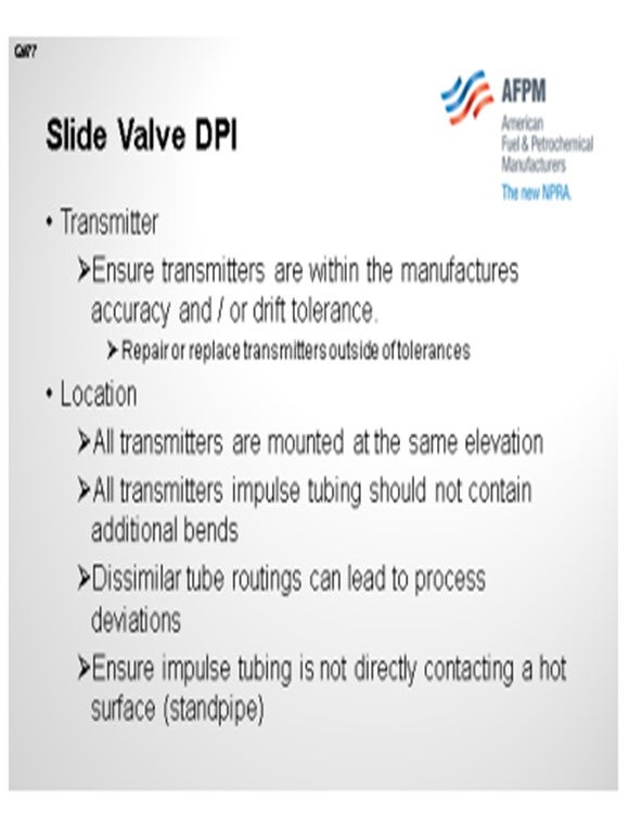
To obtain a more consistent reading, plant personnel should examine three phases: the transmitter, its physical location, and its instrument gas system. As for the transmitter, the technician should analyze it to ensure that it is within the accuracy specified by the manufacturer. In other words, you will never get all three transmitters to read 4 mADC (milliamps direct current) to 20 mADC. If within the Accu-Read meter range, the manufacturer’s tolerance for this transmitter can only read 19.8 mADC to 20.02 mADC.
In addition, the transmitter has a drift tolerance. For transmitters with drift tolerance, all you can do is identify which transmitter is drifting and then develop a frequent maintenance recalibration schedule for that device. Transmitters outside of the manufacturer’s tolerance should be repaired or replaced. As far as the physical location and routing beyond the transmitter itself, plant personnel should ensure that the location and physical condition of the three transmitters are acceptable.
Ideally, each transmitter will be physically located at the same elevation with impulse tools routed to separate process taps. Dissimilar routing will include additional bends or lines and could create small deviations in process variables. In addition, tubing that is slightly damaged, in comparison to the others, can also produce slight deviations in process variables.
Operations should also verify that none of the impulse tubes are in direct contact with a hot surface. In this case, it may be a standpipe itself. We have found that contact with hot surfaces can lead to a temperature difference, as compared to the other tubing, which may lead to a process deviation, compared to the other instruments.
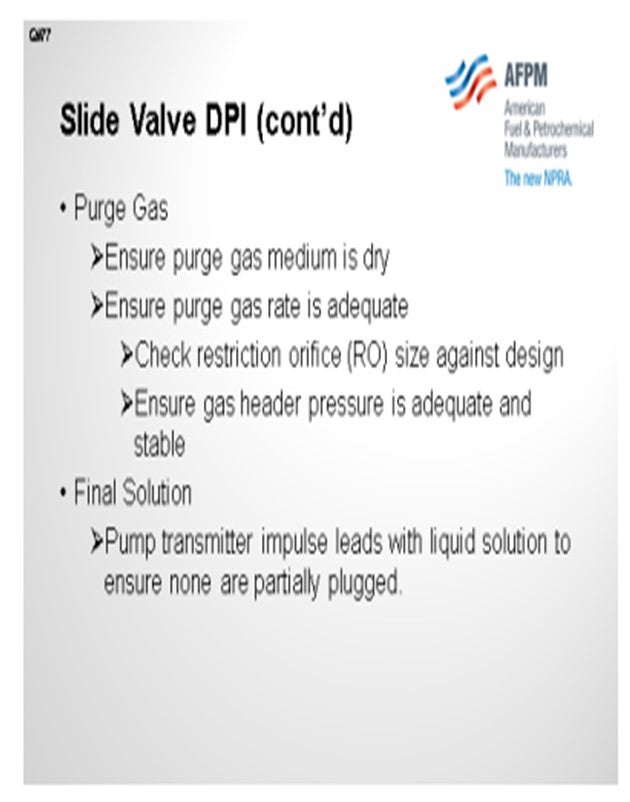
As far as the purge gas system itself, each side of the slide valve, whether regenerated or spent, will incorporate the specified purge gas medium for each tap. Plant personnel should first make sure the recommended purge gas medium is dry, and then they should confirm that the suggested flow rate is being maintained at each tap. Since an individual flow indicator for each tap is seldom present, there a properly sized restriction orifice installed with steady purge gas supply pressure to ensure that the ideal purge flow rate is obtained.
In summary, if inconsistent readings continue, prepping lids with the proper medium is the first choice. Examining, replacing, or repairing the transmitter is another option. Evaluating the routing to ensure that there are no bends or additional lines will help alleviate the deviation between the three readings.
LALL (UOP, A Honeywell Company)
I have a few additional comments. Primary contributing factors that could be considered the cause of inconsistent readings include the following:
• Instrument tapping orientation: All three sets of taps should be located in the active catalyst flow of the standpipe on the disc opening side.
• Transmitter module range selected: A range-to-span ratio greater than 10:1 can lead to a decrease in accuracy.
• Erratic impulse line purge rates, as a consequence of utilizing devices such as rotameters, can result in inconsistent purge rates being used as the critical flow orifice approach with adequate purge gas pressure.
• The physical location of the transmitters affects the readings. The closer the transmitter is to the process, the better.
• Excessive lengths greater than 15 feet can dampen the response.
• Notification or alarm on loss of purge medium is necessary to address potential catalyst plugging.
• Frequent surveillance and reaming of the process connections is recommended.
PIMENTEL (CITGO Petroleum Corporation)
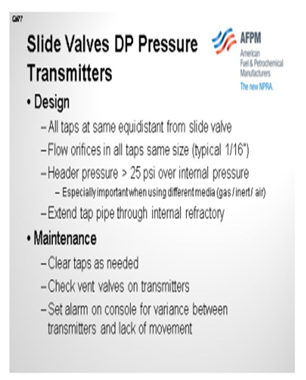
Yes, we do experience some variation between different slide valve DP (differential pressure) readings. These variations are normally caused by swings in the pressure in the purge headers. We have some design practices to minimize this effect. First, all of the taps should be equidistant from the slide valve. Second, all orifices in the taps should be the same size. Our standard is one-sixteenth of an inch. Third, you should have enough header pressure – normally 25 pounds – over the internal pressure and pipe to accommodate for fluctuations in the gas. This is especially important when you have different media in both sides of the slide valve; sometimes you have gas or inert in the reactor side and the air or inert in the regenerator side.
We recommend extending the pipe through the internal refractory layer to avoid plugging and also installing all taps on the same side of the standpipe. We do not recommend installing the taps across the standpipe, especially when your standpipe is not completely vertical. Finally, on the maintenance side, we recommend setting an alarm in your console both for variations between different DPs and also for lack of movement.
LALL (UOP, A Honeywell Company)
No reference has been provided as to what the statement “inconsistent readings” implies. In these applications, UOP generally recommends a “pre-trip” or alarm setting of 1 psi with a “trip” setting of 0.5 psi. While small inconsistencies would be expected and not considered detrimental, inconsistencies greater than approximately ± 0.25 psi could result in spurious shutdowns or even prevent a necessary shutdown from happening. Primary contributing factors that could be considered the cause of inconsistent readings would be:
1. Instrument tapping orientation: All three sets of tappings should be located in the active catalyst flow of the standpipe, i.e., they should all be in the catalyst dense phase on the disc opening side. The topside of the standpipe could experience an accumulation of gas bubbles, and this could lead to erratic readings.
2. Transmitter capabilities regarding accuracy and performance are dependent on the manufacturer.
3. Transmitter module range selected: the range/span ratio >10:1 can decrease the accuracy.
4. Erratic impulse line purge rates: Using devices such as rotameters can result in inconsistent purge rates. UOP uses the critical flow restriction orifice approach with adequate purge gas header pressure.
5. Physical location of transmitters: The closer the transmitter is to the process the better the response. Excessive lengths greater than 15 feet can dampen the response.
6. Notification or alarm on loss of purge medium is effective for addressing potential catalyst plugging of impulse lines.
7. Frequent surveillance and frequent reaming of the process connections because of the importance of these measurements as part of the shutdown system.
PIMENTEL (CITGO Petroleum Corporation)
FCC slide valve DP taps typically have one purge medium such as natural gas or inert on the reactor side of the slide valve and air on the regenerator side of the slide valve. Significant variations in pressure on one header may not be matched by the pressure on the other header. The header pressures need to be consistent. Most variations in header pressure can be buffered adequately by properly sized restriction orifices. Our typical orifice diameter on standpipe instrument taps is 1/16”. Our header pressures are normally 25 psi or more above the standpipe pressure that the purge is going into to overcome variations in process and instrument purge header pressures. Taps should be located equidistant from the slide valve. We also think that the taps on each side of the slide valve should be located reasonably close to each other versus being on opposite sides of the standpipe radially. Extend the tap pipe all the way through the refractory on the inside of the stand pipe.
Maintenance should include 1) clearing the taps if the readings are off, 2) using a hand pump to check the diaphragm of the transmitters, 3) checking the vent valves on the transmitters to see if they are closed, and 4) setting up alarms on the console to check for differentials between the transmitters, as well as for lack of movement on each transmitter, to check for stuck transmitters or plugged taps.
WILLIAMS (KBR)
To obtain more consistent readings plant personnel should examine the transmitter, its physical location and its instrument purge gas system. The technician should analyze the transmitters to ensure they are within the accuracy specified by the manufacturer. In other words, you will never get three transmitters to read 4 mADC to 20 mADC and 0 to 15 psig exactly. A transmitter can be within manufacture tolerance and only read 19.98 mADC or 20.02 mADC. Transmitters also have a drift tolerance. For transmitters within the drift tolerance, there is nothing you can do except identify which transmitter is drifting and develop a frequent maintenance recalibration schedule for that device. Transmitters outside the manufacturer’s tolerances should be repaired or replaced.
Beyond the transmitter itself, plant personnel should ensure the location and the physical condition of the three transmitters are acceptable. Ideally each transmitter will be physically located at the same elevation with impulse tubes routed to separate process taps. Dissimilar tube routings which include additional bends and/or lengths could create a small deviation from process variables. In addition, tubing that is slightly damaged in comparison to the others can produce slight differences. Verify that one impulse tube is not contacting a hot surface (standpipe, etc.). This temperature difference has also led to process deviation in comparison to the other transmitters.
Finally, check the purge gas system to each pressure tap. Each side of the slide valve, whether regenerated or spent, will incorporate a specified purge gas medium for each tap. Plant personnel should make sure the recommended purge gas medium is dry and the suggested flow rate is maintained to each tap. Since an individual flow indicator is seldom present, verifying the proper size restriction orifice is installed with a steady purge gas supply pressure will ensure the ideal purge flow rate is obtained.
If inconsistent readings continue, then pumping each lead with the proper solution will help close the gap between process readings.