Question 76: The check valve on the air blower discharge line is designed to protect the blower from hot catalyst that backs into it when the blower fails. What type of valve is used in this service, where is it located, and what is done to ensure that it closes properly?
LALL (UOP, A Honeywell Company)
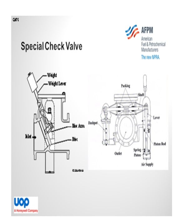
UOP specifies two special check valves in the blower discharge line. The first special check valve is installed a minimum distance from the blower discharge downstream in the snort (or anti-surge) valve in a horizontal pipe run. A second check valve is installed in the regenerator inlet line a minimum distance upstream of the air heater. The slide shows the typical arrangement of the special check valve, which is a swing-style check valve with a spring-loaded air cylinder that provides spring force-assisted closing.
An oil-filled dashpot provides dampening action on openings preventing hammering or damage. Construction is of a heavy wall of steel with 11% to 13% chrome-stainless trim. There is a stainless-steel shaft which is connected to the dashpot and lever arm as a counterweight. The counterweight supports 75% of the disc weight to minimize pressure drop. The air cylinder consists of a small piston opposed by a spring. Under normal conditions, air is supplied to the piston which moves up to compress the spring and allows the disc to open freely.
Uninterrupted operation of the FCC has led to situations during which the flapper has become stuck open. When the blower trips, the flapper does not close; and in some instances, hot regenerator catalyst is reversed into the casing of the blower. A manually operated air test valve is provided to permit equalization of the pressure on both sides of the air cylinder piston so that the spring force will move the piston downwards and exercise the valve during operation.
UOP does not know of any refiner who regularly exercises the special check valve. In our experience, check valves are frequently neglected during turnaround maintenance. During each turnaround, the check valves should be exercised to confirm ease of shaft rotation in the packing, correct operation of the air cylinder and oil dashpot, and correct counterweight and seating.
WILLIAMS (KBR)
KBR also recommends two ISO (International Organization for Standardization) check valves within the blower discharge system itself. However, due to distance in some revamp cases, we have installed one ISO check valve instead of two for blower protection. KBR also recommends the same ISO check valve type: the internal disc with external counterweight location that my colleague just described. One additional fact is that the ISO check close to the air heater should be 300-pound flange ready because of the potential exposure to high temperatures. Also, the ISO check near the blower discharge should be 150-pound flange ready.
We believe that the additional check valve is wear-warranted as it provides extra protection for the blower while only generating an added quarter to a half pound of pressure drop within the system. To ensure that the valve is properly closed, we recommend that Operations visually verify its closure with the valve position indicator, while applying pressure to the counterweight in the direction, to ensure that the check valve is completely closed.
BROOKS (BP Refining)
From an operator’s perspective, I want to add that this has become a recent focus for us at BP. We have had a few recent incidents as a result of our check valves failing. We actually had one incident where, as recommended by UOP, we rebuilt the entire check valve during the turnaround. Then during our start-up, we realized that we had actually made some errors in calculating the clearances; so, the valve hung open, despite the fact that we had done the rebuild. Therefore, you should watch for inaccurate clearance calculations that could cause valves to hang open or lock shut.
We recently had another issue when, per design, we actually had the check valve trip closed. The unit came down on a PRT (power recovery turbine) trip, and all of the equipment seemed fine; but when we came back up, the check valve did not open fully. We were then restricted on airflow from our main air blower, which affected the rest of the run before we could come down. So, despite some of our better efforts to make sure these valves worked right, and even despite the fact that the valves were working properly when we had a shutdown, we have still had other problems around these valves. We are in the initial stages of collecting information about our check valves in the BP FCC systems.
SCHOEPE (Phillips 66)
I want to quickly mention one experience. We just came out of a turnaround during which we actually opened up our check valve to inspect the internals and observed the response of the disc by pressurizing the dashpot. You also want to make sure that the valve is clean and that nothing has accumulated to prevent the special valve from closing. Unfortunately, when we started up, we forgot to commission the air to the air cylinder. After a few days, we found that this valve was in a partially closed position. Fortunately, this valve was designed with a mechanical jack that we could use to actually force the disc into a closed position. We were able to very carefully use this mechanical device until it touched the valve disk. Then, we commissioned the air to the dashpot and slowly opened the valve again.
BROOKS (BP Refining)
Most of our units do rebuilds and/or inspections on these valves at each turnaround. During a post-turnaround start-up, the check valve hung open which caused the main air blower to spin backward, destroying the turning gear motor. This failure was after a full re-build of both check valves. An incident investigation showed that the valve was rebuilt during turnaround with clearances that were too tight. Upon heat up and metal expansion, the valve hung open. Emergency steam to the air grids prevented a large portion of the catalyst from backing into the line and minimal damage was done to the air blower. However, the turning gear motor did not have a clutch disengagement mechanism when spun backwards which resulted in 20,000+ rpm and complete failure of the motor.
During another unit’s recent start-up after a power outage, the check valve hung open which caused back flow of catalyst into the casing of the main air blower motor. The FCCU was shut down, and the machine casing was found packed solid. Fortunately, there was no damage to the blower, and it was cleaned, inspected and brought back online.
A different unit experienced a failure in this check valve during a unit trip. When this unit tripped, the valve closed but failed to reopen fully upon restart, which caused a significant reduction in air rates to the unit.
Due to the abundance of failures around these check valves, we have recently started an investigation around our sites’ valve characteristics (close/open assists, external weight assists, reliability, types, etc.) and are in the initial stages of data collection with the intent of developing recommendations to our sites.
WILLIAMS (KBR)
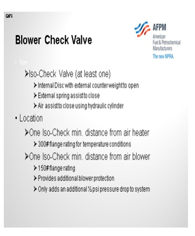
KBR typically installs at least one ISO check valve in the air blower’s discharge line. The ISO check consists of an internal disc with external counter weight to help hold the valve open during normal operations and a spring assist to help close the valve in the event that air blower operations are interrupted. Some refiners use an air-assist ISO check instead of the spring to fully close the valve during emergency situations. Here air applies pressure to a hydraulic piston that closes the valve when the low flow alarm is triggered.
In cases where the distance from the air blower to the regenerator is excessive, KBR recommends an additional ISO check within the system. One ISO check is located at a minimum distance from the blower (downstream of the anti-surge vent valve), and a second ISO check valve is at minimum distance from the air heater. The check at the air heater is to prevent catalyst back flow from the unit if air is lost. The additional check valve near the blower serves two basic purposes. First, in the event that the second check does not seal properly, this check valve provides an additional level of protection for the blower. Also, as the check valve closest to the air heater closes, the higher pressure air volume trapped upstream of the check valve does not reverse-flow through the anti-surge valve against the blowers discharge as it is relieving. KBR believes that the additional check valve is well warranted as the additional valve typically only provides an additional pressure drop of ½ psi (pounds per square inch) to the system at normal flow rate. The check near the blower is 150-pound rated, and the check near the air heater is 300- pound rated because of the potential high temperature.
To ensure that the valve is properly closed, we recommend that Operations visually verify its closure with the valve position indicator while applying pressure to the counterweight lever in the direction to ensure the check valve is completely closed.
LALL (UOP, A Honeywell Company)
UOP specifies two special check valves in the blower discharge line. The main air blower special check valve is installed on the discharge of the air blower. The regenerator inlet air special check valve is installed just upstream of the inlet to the direct-fired air heater. If the blower starts to surge, the large volume of the regenerator must be isolated from the blower. Otherwise, serious damage could occur to the blower. The main air blower discharge special check valve helps protect the blower during surges. Fluidized catalyst can easily flow back through the air heater if pressure is lost. The regenerator inlet air special check valve helps to prevent backflow of catalyst to the blower. Figure 1 and Figure 2 show the check valve and its associated equipment.
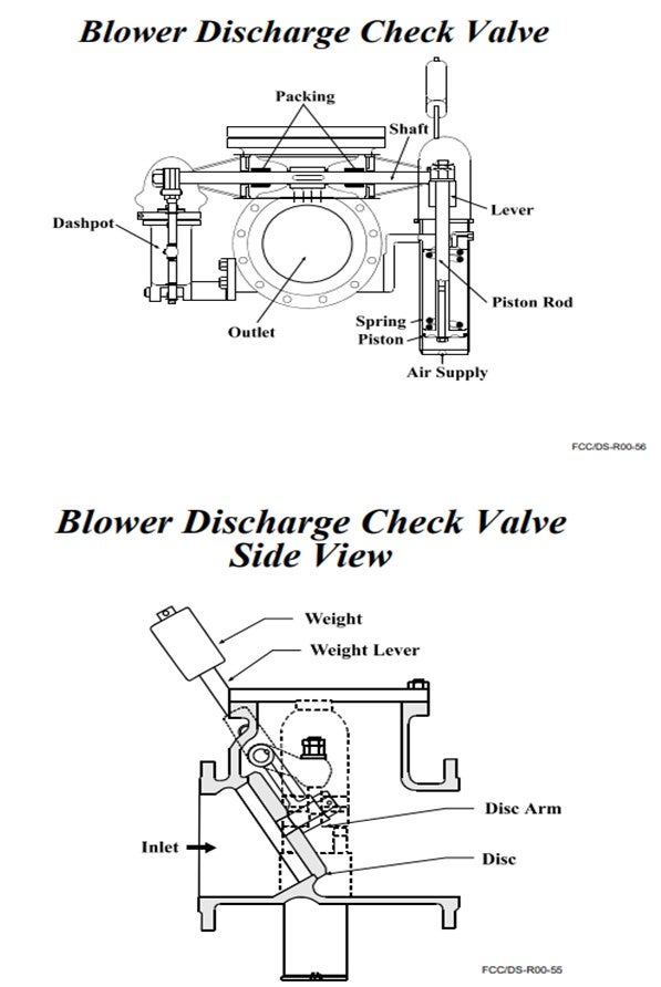
The special check valve is a swing style check valve with a spring-loaded air cylinder that provides spring force assisted closing. An oil filled dashpot provides a damping action on opening to prevent hammering and damage. Construction is of heavy wall steel, to resist temperature and pressure stresses, with 11% Cr (chrome) to 13% Cr or stainless trim. The stainless-steel shaft is supported by hardened stainless steel bushings with GRAFOIL® packing used to prevent leakage. The shaft is connected to the dashpot and to a lever arm that has counterweights. The counterweights support 75% of the disc weight to minimize the pressure drop through the valve. The counterweight should never hold the disc open when there is no air flow. The lever arm is usually cut to the proper length in the factory, and the weights are set in the field.
The air cylinder consists of a small piston opposed by a spring. Under normal conditions, air is supplied to the piston, which moves up to compress the spring. The piston rod moves freely between two small lever arms attached to the check valve shaft. As the piston rod rises, the valve is free to open. Air flow from the blower forces the valve open. The air to the piston is supplied through a three-way valve that will vent off cylinder pressure when actuated. For new units that have venturi meters on the blower discharge line, a low flow signal will alert the valve to cut off the air supply to the special check valve. Instrument air failure will also vent off pressure from the cylinder. Upon initial venting, the spring provides a sharp thump to the valve shaft to help free the disc in the event that it has become slightly stuck in the open position. The force of the spring is not enough to close against the normal operating air flow from the main air blower.
A manually operated air test valve is provided which permits equalization of the pressure on both sides of the air cylinder piston so that the spring force moves the piston downward and exercises the valve during operation.
Extended periods of uninterrupted operation of the FCC with the check valve in the open position have led to situations in which the flapper has “stuck” to the top of the check valve body over time. When the blower trips, the flapper in the special check valve does not close; and in some instances, hot regenerated catalyst has reversed into the casing of the main air blower.
UOP does not know of any refiner that regularly “exercises” the special check valve at the discharge of the main air blower. Some refiners do activate the air actuator mechanism periodically, but we are not aware of anyone who exercises or moves the check valve flapper.
At each turnaround, it is recommended that the special check valve be opened, inspected, and maintained by qualified personnel. In our experience, special check valves are frequently neglected during turnaround maintenance. During each turnaround, with the air blower shutdown and after any maintenance has been completed, the check valve should be exercised to confirm ease of shaft rotation in the packing, correct operation of the air cylinder and oil dash pot, and correct counterweighting. Contact the check valve manufacturer for additional recommendations.