Question 73: What is the current design philosophy in the lower section of a coker main fractionator (from tower bottoms up to first product draw) for controlling product quality and coke fines buildup?
SRIVATSAN (Foster Wheeler USA Corporation)
The main objective is to keep the coke fines agitated and then efficiently remove them from the bottom of the fractionator. A properly designed coke drum with low vapor velocity helps minimize the coke fines carryover to the fractionator. Proper C factor for tower sizing is critical to achieving the HCGO quality in low pressure cokers.
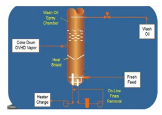
Now from a licensee standpoint, I am going to discuss the Foster Wheeler design illustrated on the slide. The DCU feed in our design is introduced directly into the fractionator, and the residence time is built into the fractionator. The feed is introduced through two rings: an outer ring and an inner ring which has holes in the bottom. It also has open ends directed towards the standpipe that is above the heater charge nozzle. What is happening is continuous agitation of the fractionator bottoms. We also provide an effective fines removal system that consists of a bar cage inside the fractionator, an external basket strainer, and a fines removal pump. On the slide, the bar cage is shown next to the standpipe. The objective of the bar cage is to remove relatively large particles out of the fractionator and trap them in the basket strainer that is outside. A fines removal pump takes a slipstream of the heater charge and then pumps it to the heater suction and out of the fractionator. The standpipe itself prevents particles – one-half inch and larger – from entering the heater. So, it is all filtered within the fractionator itself. The heater charge pump also has a coke-crushing impeller that can remove particles that are one-half to three-quarter inch in size.

The coke drum overhead vapor enters below the shed trays. We employ shed trays for a couple of reasons: 1) They distribute the vapor, and 2) they serve as entrainment trays for the coke and tar particles. One could do away with the sheds, but there would be a slight effect on your HCGO quality. As the coke drum overhead vapor rises, it is contacted with a wash oil stream above. Since the cokers that are designed for maximum liquid yields operate under the lowest recycle possible, we employ an open wash zone. We do not have trays or sheds. It is an open wash zone using spray headers and full cone nozzles. The wash zone sprays help maintain the HCGO quality and also provide good control of the recycle. We also have a heat shield to prevent contact of the flash zone vapor with the pool of liquid. Again, this is an effective way to control your recycle operation. Further, for the HCGO and LCGO draws, we employ total draw pans in the fractionator. The two pictures on the slide show the fractionator internals. On the left is the standpipe, and on the right is the bar cage. You can also see the ring.

SLOLEY (CH2M Hill)
I will focus mainly on the section above the bottom boot. Different licenses have different approaches in this area depending on their balancing capacity, reliability, and performance. There is no real clear-cut answer for this, but there are various combinations that are more common. The bottom section typically includes some type of recirculation system along with the coke catcher design and coke crusher pumps in the bottoms.
Two major purposes of the area above the feed entry are the entrainment of coke fines and the control of the recycle at the heavy ends of the coke drum. The overall product yields and unit capacity favors minimum recycle. This creates a severe combination of operating conditions and mechanical design criteria. Within these constraints, what is most common are (1) spray chambers and (2) baffle trays which may be either disc-and-donut trays in smaller units or shed trays in larger units.
In some older units, you saw conventional sieve trays. In modern units, spray chambers or spray chambers combined with baffle trays are the most commonly used configuration. High recycle rate units, however, make a grid wash more attractive.
Spray chambers have the major benefit of maximum reliability. There is nothing in the area underneath the sprays for coke to form onto, thus minimizing coking. Nevertheless, coke stalactites can form from the spray header itself; so the spray header needs to be strong enough to support this weight without collapsing.
Overall, spray chambers work well because they operate at low liquid rates. Against these benefits, spray chambers have a relatively low capacity for the same product quality because they are not as effective in the entrainment.
Baffles, either shed trays or disc-and-donut trays, require high liquid rates to be truly effective for de-entrainment. Few delayed cokers really have recycle liquid rates high enough for the trays to create a liquid curtain that makes them truly effective for entrainment removal. At low liquid rates, the trays also tend to coke because even small issues with installation of the trays out-of-level lead to zones on them where they have very low liquid at one end and high liquid rate at the other.
However, even when coked, the baffles rarely shut down the unit because of the large spacing between the baffles gives lots of space for coke to form without imposing pressure drop or flooding of the unit. A few units have used fresh feed to the unit going onto the shed trays to create the liquid curtain. However, this has a dramatic effect on the fractionator’s heat balance because it is cooling the vapors as they go up the tower and reduces total liquid yield.
The overall best approach tends to be a mixture of baffles and sprays. It gives better performance than a simple spray chamber. However, the baffles are still not completely effective. Grid washes are typically used in units that have high liquid recycle rates for process reasons. They are very effective in entrainment removal. However, they still have a risk of coking that is more significant. It is seen as an overall risky operation.
Conventional trays are rarely used below the heavy coke or gas oil for new units. If you look at the figures, highlighting a point previously mentioned, you will see that the first three designs all use a total collector tray above the spray, baffle trays, or grid wash. This gives better overall control of the low liquid recycle rate. Most units with trays in them have a partial draw of liquid which gives relatively poor control of the liquid rate, and one reason that makes them truly only suitable for high recycle units.

Equipment cost differences between these are fairly limited. You should never let equipment cost between these configurations drive the selection process criteria, unless it significantly affects tower diameter. It should be the selection driver.
HERLEVICH (Marathon Petroleum Corporation)
I want to share some experiences from our cokers. We were able to achieve a seven-year run on our main fractionator when employing the flash zone gas oil strainer system, and we also have experiences from other cokers that only made a three-year run. In the area of fines removal, I would point out that there is also a proprietary design being used which employs sloped trays and a sump as another alternative to the method that Srini discussed. So, there are a few ways to design these systems.
JOHN GORDON (The Dow Chemical Company)
What kind of monitoring methods does the industry use to track the accumulation of solids in the bottom of the coker fractionator?
PRIBNOW (CITGO Petroleum Corporation)
I think we ran 10 years on our coker for the turnaround cycle. You saw the pictures of the standpipes and how plugged they can get, so we monitor delta P on the standpipes. We also did thermal scans on the bottom where we pulled insulation from the bottom of the tower. We could often see how high the coke level was in the bottom of the tower relative to the location of the nozzles and the standpipes. It is not perfect, but at least it gave us some idea of whether we could make a 10-year run or if we would have to take it down in a year.
SRIVATSAN (Foster Wheeler USA Corporation)
You also have the nuclear level gauges at the bottom of the fractionator which should give you an indication of the coke level.
SRINI SRIVATSAN (Foster Wheeler USA Corporation)
The main objective is to keep the coke fines agitated and efficiently remove them from the fractionator. A properly designed coke drum with low vapor velocity helps minimize coke fines carryover to the fractionator. Proper C factor for tower sizing is critical for achieving HCGO quality in low pressure cokers.
In Foster Wheeler designs, the bottom section of the fractionator is kept agitated by bringing the entire feed through an inner and outer ring with rightly oriented holes in the bottom and open ends. The bottom section of the fractionator also has a tall standpipe and a bar cage with a fines removal system that serve as internal “filters” for coke fines removal.
The heater charge pump is equipped with a coke crushing impeller.
Coke drum overhead vapor flows to the coker fractionator and enters below the shed section. The sheds serve to distribute the vapor and as de-entrainment trays for coke and tar particles that could be entrained with the coke drum overhead vapor. Eliminating the shed trays could lead to slightly increased contaminant levels in the HCGO.
As the coke drum vapor passes upwards through the shed section, it is “washed” by an induced reflux, and a recycle stream is condensed. For ultra-low recycle designs, in order to optimize yields, we employ an open wash zone below the HCGO pumparound draw and above the shed decks. Wash oil is sprayed using spray headers with full cones ensuring full coverage. The wash oil serves to maintain HCGO quality in terms of asphaltene, metals and CCR.
Low recycle control is facilitated by segregating the feed liquid pool from the hot flash zone vapors utilizing a heat shield and feed arrangement that eliminates splashing.
Above the wash section of the coker fractionator, heavy coker gas oil (HCGO) pumparound and product are withdrawn from a total draw pan.
The schematic below illustrates the Foster Wheeler fractionator internals.
EBERHARD LUCKE (CH2M Hill)
As far as I know, the fractionator bottom design has not changed much over the last years. The bottom draw (heater feed) has a slotted standpipe to keep coke particles in the tower, protect the heater charge pumps, and maintain a decent heater runtime between decoking shutdowns. Most heater charge pumps are also protected by suction strainers and/or a coke-crushing impeller design. The tower should also have a carefully designed bottom circulation system that takes the bottom product and routes it through a filter system before returning back to the tower bottom. If designed properly, a big portion of the coke fines will be caught in those filters and be removed from the system. Between drum vapor inlet and HCGO draw, the gas oil recycle system in the wash zone not only quenches the drum vapors to condense part of the stream, it also removes coke fines from the vapor stream and washes those down into the bottom. Wash zone designs vary from open spray chambers to disk and donut sections. Both can work if the required wash oil flow rate is maintained. In many cases, coker economics and ultra-low wash oil rates allow more coke fines to move up into the HCGO section. I would like to add that the same careful consideration needs to be given to the source of the coke fines, coke drum vapor outlet, and vapor velocities in the coke drum and in the vapor outlet nozzle, as well as any foaming issues observed in the coke drums.