Question 72: What are potential causes of damage to the top section of coker main trays? What mechanical and process considerations are used in designing the top section trays for more reliable operation?
SRIVATSAN (Foster Wheeler USA Corporation)
Damages to the top section of the coker trays could be due to process-related reasons or mechanical or operational issues. One process-related reason is salt deposition. Usually, the salt is ammonium chloride. It is water-soluble, corrosive, and rapidly deposits at the right conditions, leading to severe loss of tray capacity and efficiency. The deposition is accelerated at low overhead temperatures, which may happen when you have too low of a reflux temperature or water coming in with your reflux stream. Low overhead temperatures could also result if you have too low a naphtha-LCGO (light coker gas oil) cut point. If you want to maximize your diesel fraction and are operating in a maximum diesel mode, the lower naphtha endpoints could lead to lower top section temperatures in the fractionator which accelerate the deposition of ammonium chloride. Normally the deposition is between LCGO draw and the column overhead. Some operations have also experienced salt deposition due to the presence of organic chlorides. Also, if you are adding slops directly to the fractionator, you must be careful to watch for the free water and salt content. We normally recommend having an external heater to dewater the oily slops before they are introduced into the fractionator.
Considerations for proper design include identification of the chlorides in both the crude and VR feeds and improving desalter operation. While this may help avoid deposition of inorganic chlorides, organic chlorides are not removed in the desalter. By introducing water intermittently though the reflux line, your ability to wash the top section of the trays will also help mitigate salt formation. The water is drawn off of several trays below and disposed.
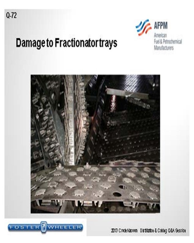
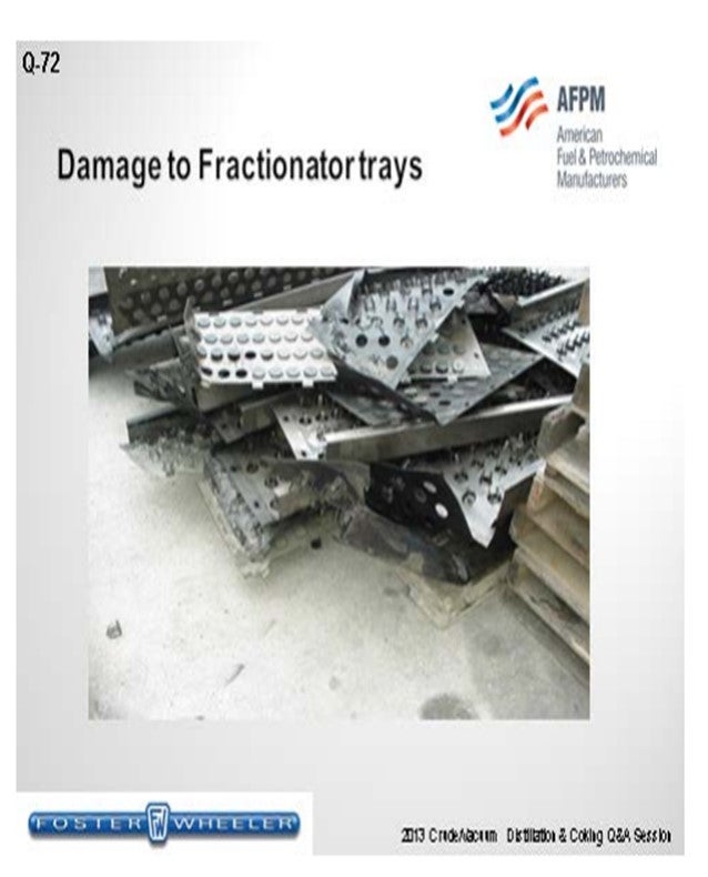
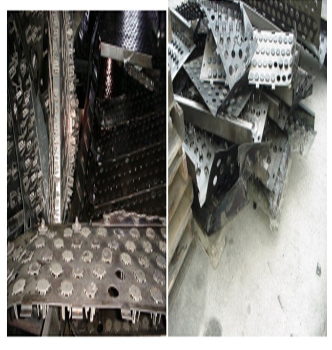
Increasing the overhead temperatures is probably one of the better ways to control salt deposition and prevent the salts from precipitating in the trays. You could also balance the heat removal between your overhead condenser and the pumparound streams. If you have a low naphtha endpoint, a backend naphtha splitter could be used. Finally, the fractionator overhead drum has to be designed for adequate hydrocarbon and water separation. Operational issues can occur when water is introduced into the fractionator, which then causes a blowout of the vaporized water. We know of one instance during a startup operation when the spare LCGO pumparound pump, which had not been completely drained of water, was started. The rapid expansion of the vaporized water caused by the high temperature in the fractionator blew the top section of the trays between the LCGO section and the overheads. These slides show that event.
Incorrect metallurgy in the top section could also result in damage to the fractionator top section. The correct metallurgy depends on the feed stock and contaminants. Normally, the material of construction – if you are processing, say, an Arab medium-type feed – is killed carbon steel from the bottoms up to the LCGO draw with 1/8-inch corrosion allowance and 410 stainless clad. Above the LCGO, it is normalized carbon steel with a 1/8-inch corrosion allowance. The trays are 410 stainless, and the distributor pipe and spray nozzles are 304L stainless. Foster Wheeler designs the overhead piping, fractionator condenser tubes, and the water boot in the reflux drum for a much higher corrosion allowance.
SLOLEY (CH2M Hill)
I want to reiterate that the occurrence of chlorides in most delayed cokers is nearly inevitable. Nearly everyone with a delayed coker will eventually end up waterwashing it, at least intermittently, in the top. When we have put the water back in the tower in the reflux, we have seen relatively few events of it causing tray damage because of that operation. If you look at the mechanical design limits that are standard in the industry for trays, you will see that trays are designed for a 60-pound per square foot distributed load on top and 300-pound point load for installation purposes. The key point is that all of the load is on top pushing down, and the tray rests on the tray ring. When you have an incident, as Srini just discussed, where water is being put in the tower lower down in a hotter section, the stress load is coming up the tower and trays are inherently extremely weak for a load coming up beneath them.
That is the real risk of tray damage comes from pressure surges from below Risks from water wash introduced in the naphtha are relatively modest to low You should not let that perception of risk prevent you from waterwashing the tower. If you damage trays more than once during water washing, you should really investigate your procedures around how you are adding the water. You should also look at mechanical solutions that make the trays much stronger. These are relatively inexpensive. However, the procedures and operational issues count as well.
SRINI SRIVATSAN (Foster Wheeler USA Corporation)
Damages to the top section of the coker main fractionator trays mainly occur due to Process related issues or Operational/Mechanical issues. Process related causes include:
• Salt deposition in the upper section of the trays, accelerated by low operating temperatures in the section. Usually the salt is ammonium chloride (NH4Cl) formed when chlorides in the VR feed, carried as a result of improper desalting, react with NH3 formed as a byproduct of thermal cracking. The ammonium chloride salt is water-soluble, corrosive, and deposits rapidly leading to severe loss of tray capacity and efficiency. Deposition is normally between the LCGO draw and the column overhead. If the overhead temperature in the fractionator approaches the salt deposition temperature, there is an increased risk of salt deposition and corrosion.
• We have also observed that some operations are prone to salt deposition in the top section of the fractionator due to the unexpected presence of organic chloride species. The temperature at the heater outlet is high enough to break the C-Cl bonds forming HCl as a result of hydrolysis, which then reacts with NH3.
• Introduction of slops straight into the fractionator also increases the risk of fractionator fouling if the slops contain free water and chlorides.
• Too low of a reflux temperature or too much water entrained with reflux can cause salt deposition and subsequent corrosion. Considerations for proper design include:
• Identification of chlorides in both crude and VR feeds.
•Improvements in desalter operation: While this may help avoid deposition of inorganic chlorides, organic chlorides are not removed in the desalters.
• Water-washing tower online: Foster Wheeler fractionator designs now include the ability to wash the top section of the trays by introducing water intermittently through the reflux line. The water is drawn off several trays below using draw-off pans to a flow-through waterwash coalescer, followed by their disposal.
• Increasing overhead temperature to ensure sublimation of salts, thus preventing the salts from precipitating in the trays: The salts are carried with the overhead vapor from the fractionator. Intermittent waterwash and condensation of the overhead vapor results in the salts dissolving in water and being drawn out as sour water. Low overhead temperatures can also occur when you have a low naphtha-LCGO cutpoint. A backend naphtha splitter could be used if lower naphtha cutpoint is desired.
• Balance heat removal between overhead condenser and pumparound streams: Optimizing the heat removal between the overhead condenser and LCGO/HCGO pumparound streams will lead to more desirable top tray temperatures
• Fractionator Overhead Drum: Design these drums for adequate HC-water separation.
• Fractionator Overhead Drum: Design these drums for adequate HC-water separation.
Operational issues occur when water is introduced into the fractionator causing a blowout of the vaporized water. We know of one instance during a startup operation when the spare LCGO pumparound pump, which had not been drained completely of water, was started. The rapid expansion of the vaporized water caused by the high temperature in the fractionator blew the top section of the trays between the naphtha and LCGO sections in the fractionator. Below are photographs showing the damage.
Incorrect metallurgy in the top section could also result in damage to the fractionator top section. The correct metallurgy depends on the feedstock and contaminants. Typical material for the construction of a coker main fractionator processing typical Arab medium feed is as follows: - Bottom-up to LCGO Stripper Draw-Off: normalized KCS clad with 1/8” 410S SS - Above LCGO Stripper Draw-Off: normalized KCS: 1/8” Corrosion Allowance - Trays: 410-S stainless steel (SS) - Distributor Pipe and Spray Nozzles: 304L SS Foster Wheeler also designs the overhead piping, fractionator condenser tubes, and water boot in the overhead reflux drum for a higher corrosion allowance.
DENNIS HAYNES (Nalco Champion Energy Services)
One potential cause of damage is the deposition of ammonium chloride salts plugging the top section and also causing underdeposit corrosion. This type of deposit can form due to hydrogen chloride and ammonia partial pressure levels and temperature requirements for the system. Therefore, feed quality is another consideration. In systems where this becomes a concern, salt dispersant additives have been applied to minimize ammonium chloride deposition, plugging, and corrosion.