Question 65: What variables impact feedstock atomization in the FCC riser? What steps do you take to optimize the feed and catalyst mixing for proper vaporization and catalytic reaction?
TRAGESSER (KBR)
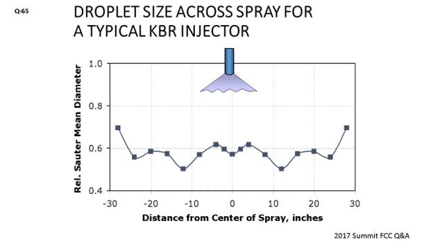
One of the primary variables used to measure atomization is the droplet size of the oil produced by the feed nozzle: The smaller the liquid droplet, the more quickly it can vaporize and start the gas phase reactions with the catalyst. Most FCC feed nozzles are tested using water and air, and the most common method for measuring the droplet size is to calculate the Sauter mean diameter, which is basically a ratio of the total volume of all the droplets divided by the total area of all the droplets. It has been described as the best measure of the fineness of a spray.
KBR’s Atomax™ feed nozzle use the energy from the steam to help shear the oil into fine droplets. On the slide is a diagram of KBR’s nozzle which shows the small orifices injecting steam into the oil stream. This design allows us to use a lower oil-side dP to achieve atomization.
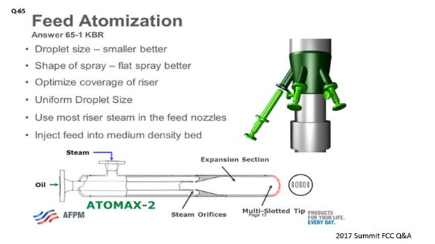
One of the goals of an FCC feed nozzle is to produce a fine spray of droplets across the entire spray pattern; meaning, you do not want a mix of small and large droplets. Ideally, they should all be small.
The design of the feed injection zone is also important. The goal is for the nozzle spray to cover the entire riser cross-section without too much overlapping between nozzle sprays. The catalyst should then ideally flow up through the oil sprays from the nozzles in plug flow for ideal contacting. KBR’s design philosophy is to use a medium catalyst density for contacting the oil. Also, it is our philosophy to use most of the riser steam in the feed nozzles.
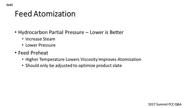
Another variable for feed atomization is hydrocarbon partial pressure; and the lower the value; the better for cracking reactions. One way to do this would be to lower the reactor pressure; however, the pressure in a reactor is limited by the pressure drop between the reactor and wet gas compressor. The suction pressure at the wet gas compressor should always be positive to ensure that there is no air leakage into the system. Another negative aspect of low pressure in a FCC is that it makes everything larger, such as the reactor and regenerator vessels themselves, cyclones, and the main fractionator, which are all sized based on velocity. The best way to lower hydrocarbon partial pressure is with dispersion steam used in the feed nozzles, which not only helps lower partial pressure but also helps with atomization. KBR typically specifies 2 wt% dispersion steam for a gasoil feed, going all the way up to 5 wt% for a heavy resid.
Feed preheat temperature can also be considered as a variable for optimizing feed nozzle performance. This is because increasing the temperature reduces feed viscosity and therefore, in theory, aids atomization. However, the benefit of lower viscosity does not necessarily offset the benefit gained from increasing the cat/oil ratio at lower feed temperature, which is a more important variable. Therefore, the feed preheat temperature should be based on what is required for optimizing the product value of the unit – from a cat/oil standpoint – and not to lower viscosity of the feed.
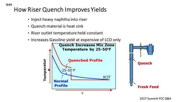
One way to increase the cat/oil ratio and also maintain a high feed preheat is using a technology called ‘riser quench’ where heavy naphtha is injected midway up the riser. This process increases the cat/oil ratio and temperature in the lower riser, which is then quenched to prevent overcracking. This process is especially useful for resid feedstocks to aid in vaporization. The yield benefit is an increase gasoline yield at the expense of LCO.
While I have spent a lot of time talking about the design of the feed injection system, there is a reason for that; and that is, there is not a lot of optimizations to do once you have your system other than to run it as it was designed. Regarding the feed nozzles, the only knob you really have to turn is the dispersion steam. However, for a given design, there is not necessarily a lot of room to increase the steam due to concerns with attrition and erosion of the nozzle tip. However, you may be able to add more steam to the riser with the available wye aeration, either through an individual riser or a fluidization ring.
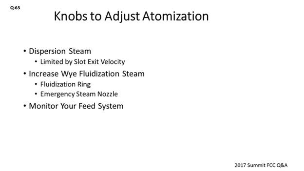
I would like to end by mentioning that it is really important to monitor your feed nozzle system to ensure that it is working optimally. Depending on your design, this would typically involve monitoring dPs for a given flow where an increase could indicate plugging, or a drop may indicate cap erosion.
BHARGAVA (KBC Advanced Technologies, Inc.)
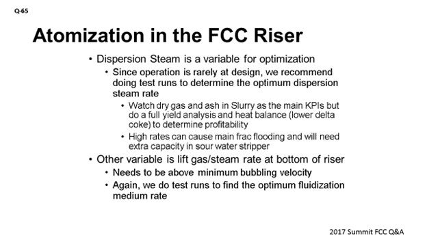
Steve covered most of the variables. The biggest is, of course, design. If there is something wrong with the design, it is hard to compensate. Therefore, all of the improvements come with the design. Once you have the design, then the only two variables you really must adjust are dispersion steam and the steam rate at the bottom of the riser. Again, we have used higher dispersion steam rates to maximize conversion. Your steam conversion increases off more than 1 to 1.5% just by optimizing the dispersion steam. As you already know, once you finish the design, you have to optimize the steam because everything on the unit is different from the design basis. The velocity of the steam and the viscosity of the feed can all be compensated for by doing a routine test run on dispersion steam to determine the optimum steam rate. There is a lot of money to be made, so it is almost worth doing such test runs every time you see a big change in the unit. Or, you could even do it routinely once a year to identify the optimum dispersion steam rate.
When we did the test run in one of our client sites, we saw that as we increased dispersion steam, there was a definite increase in conversion. But beyond a certain critical point, we saw the ash in the slurry go up significantly. With the gasoil operation at 3.5 wt%, we started seeing a major increase in ash because of attrition. We also saw that when we raised the steam rate too much, there was a big effect on the sour water stripper, which prevented us from doing the full optimization. However, we were able to get most of the benefit from these tests.
The other variable is lifting gas or steam rate at the bottom of the riser. Again, if you have a very good model, you can find that small changes in lift gas can have a major impact on your conversion. It was not as dramatic as dispersion steam, but we have seen about a 0.5% increase in conversion when optimizing the amount of fluidization steam between minimum bubbling velocity to the point where you get dilute-phase transport. That variable is very significant as well.
MALLER (TechnipFMC Process Technology)
Certainly, a variable impacting atomization is the viscosity of the feed. We have seen units that run very heavy high viscosity oils, and which tend to run lower preheat to in an attempt to reduce regenerator temperatures. There is certainly a tipping point where if you go too low, the viscosity will become so high that you will not be able to adequately atomize the feed anymore.
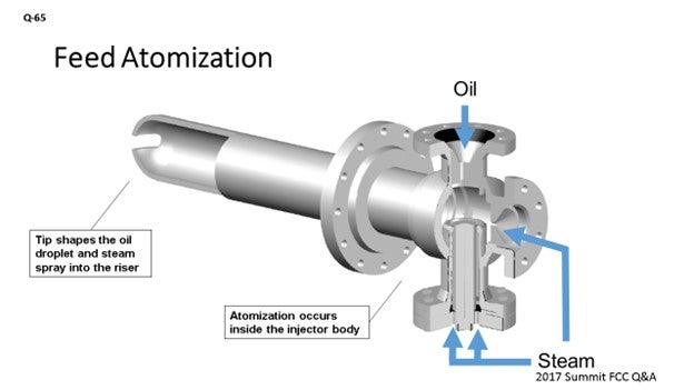
Another important factor I want to highlight – other than atomization – is the penetration of feed into the riser, which certainly becomes important for very large diameter risers. You can imagine that for injectors that are depending on shearing of the oil right at the tip, as soon as that oil is leaving the tip, it is impacting the catalyst. If that is the main mechanism for atomization, the droplets will not get far into the riser because the liquid oil ligaments are directly contacting the catalyst. The TechnipFMC injector on the slide shows that the atomization is occurring on the backend of the injector in the mixing chamber, away from the catalyst. Droplets are then transported by steam out of the tip. The angle of the injector – with respect to the riser – can be adjusted to ensure adequate penetration to the center of the riser.
KEVIN KUNZ [Shell Global Solutions (US) Inc.]
At the AFPM FCC seminar, and then followed up in this past spring’s Annual Meeting, Shell presented two papers on the development of feed nozzles. I like Steve’s comment about how droplet size is typically measured for Sauter mean diameter using water and air as proxies for oil and steam. The key to ensuring good droplet size distribution is to have the right analytical technique to image the spray. Many analytical techniques do not measure non-spherical droplets, and, as a result, skew the calculated Sauter mean diameter.
There are many different measurement techniques for measuring the droplet sizes. Shell does research on feed nozzles and uses the Shadowgraph Particle Image Velocimetry technique, which captures images of a representative cross-sectional area of the spray. This technique also measures and quantifies the non-spherical droplet portion of the spray, thus providing confidence that the calculated Sauter mean diameter is correctly calculated. Shell has presented two AFPM papers on our recent developments of feed nozzles: CAT-16-832 and AM-17-46.33 These papers discuss, in detail, the analytical techniques used to measure droplet sizes, the design changes we have made to ensure smaller droplets and fewer and smaller non-droplets, and the performance improvements obtained at our Deer Park FCCU after installation of these design changes.
ALEX MALLER (TechnipFMC Process Technology)
Feedstock atomization typically comes down to the design and reliability of the feed injector. Obtaining good atomization of the feed is important for optimizing the performance of any FCC. Feedstock atomization facilitates the rapid and efficient vaporization of the feed inside the riser, which can then initiate the cracking reactions. Larger droplets will require contact with more catalyst particles to supply the heat required to vaporize, which can lead to more thermal cracking and coke deposition on the catalyst.
Another equally important factor impacting feed/catalyst mixing for proper vaporization in the riser is the ability of the feed to penetrate the riser so as to achieve maximum coverage of the cross-sectional area. This aspect is even more important for very large risers. Every feed injector licensor has videos of their feed injectors spraying water into the air to demonstrate the fine mist created. Imagine, if you will, that mist immediately contacting a wall of catalyst at the tip of the injector. Injectors that are relying on shearing at the tip to achieve atomization may actually end up having the oil ligaments coating the catalyst before they break apart into small droplets. An ideal system will have the droplets exiting the injector already atomized. The oil droplets, travelling within a buffer of steam, should have sufficient momentum to penetrate into the riser with a fan pattern that maximizes the contact of oil and catalyst.
As risers get larger, the number of injectors utilized should increase, spaced equally around the riser for maximum coverage. Also, the angle at which the injector is set, relative to the riser, is important for ensuring penetration to the riser center. For larger risers, a higher angle relative to vertical can be utilized.
Regarding the condition of the catalyst in which the feed is injected, there are two schools of thought: inject into dense catalyst or dilute catalyst. Both options can work, and each licensor has a preference. What is important is that the flow profile of catalyst is as uniform as possible, which can be difficult due to the change of direction the catalyst typically encounters as it enters into the riser.
SANJAY BHARGAVA (KBC Advanced Technologies)
Modern FCC nozzles generally have a “single”-point design which defines the feed rate, viscosity, and amount of steam used by the designer/licensor. The difficulty is that most FCCs rarely run at the design point. Proper design and process variables are both needed for feedstock and catalyst distribution at the feed injection zone to optimize the feed and catalyst mixing.
Good practices for optimal feedstock distribution include review of the design of the nozzles and also to consider the following:
-
Pressure drops,
-
Nozzle velocity, and
-
Viscosity/surface tension of oil at temperature of injection.
The two variables that impact atomization or droplet size are pressure drop and viscosity of the oil. The viscosity of the oil – at process temperature – will indicate the ability to form the fine mist, while the nozzle delta P (pressure differential) provides an indication of size of the droplet that may be formed.
In addition, the other variable affecting atomization and vaporization is dispersion steam. The optimum steam – and thus, nozzle performance – is established by doing multiple tests runs at different steam rates and then studying the results of the test runs. Historically, the dry gas yield has been an indicator to find the optimum dispersion steam rate for a given feed. However, along with this exercise, a detailed review of the heat balance should be completed as there may be benefits in lowering the delta coke from improvements in catalyst/oil mixing.
Dispersion rates that are too high will cause excessive erosion of nozzles (eventually resulting in poor distribution) and excessive catalyst attrition and can unduly burden the main fractionator (flooding) and the sour water stripper systems. Lower dispersion rates can result in lower atomization and vaporization, resulting in lower conversion and – in some instances – coke in the reactor/cyclone system.
Catalyst distribution, which promotes minimum slip, will lead to the best distribution. Pre-accelerating the catalyst with dry gas or steam via introduction of the catalyst below the feed nozzles results in an evenly distributed catalyst with minimum backmixing at the point of contact at the feed nozzles. The optimum superficial gas velocity should be higher than minimum bubbling velocity and lower than choke velocity and is a function of catalyst mass flow rate and diameter of the pre-entry zone. In addition, the riser requires a vertical length to establish close-to-plug flow. The optimum is, again, decided by doing a series of test runs to determine the optimum.