Question 64: What are the risks and negative factors you see associated with processing slurry oil, either as slurry separator backwash or recycle, in the FCC reactor?
MALLER (TechnipFMC Process Technology)
The two processes mentioned here are very different. Slurry recycling is typically utilized on units that are short on their heat balance as a means of making more coke and keeping the regenerator hot enough to continue to operate. The intent of the slurry separator backwash is to return fines that are being removed from your now-clarified oil back to the reactor/regen system, ultimately pushing the fines out of the regenerator side. The negative factors with the slurry separator backwash are that 1) you are recycling that heavy material back into the riser and 2) it will increase your delta coke. One mitigation – if it is a filter – is to displace the slurry from the element with a different material, such as HCO (heavy cycle oil), prior to backwashing. That way, the material injected into the riser will have less coke precursors than slurry. Another mitigation for that increase in delta coke is to minimize the amount of backwash being used. Most of the modern systems, depending on the technology, should be able to operate efficiently with backwash rates down to 1 vol% (volume percent) of the unit’s fresh feed flow rate.
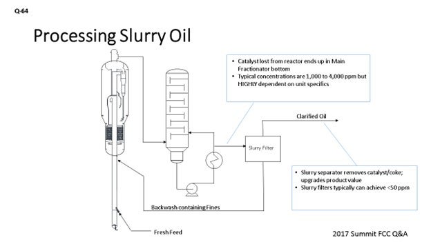
A consequence that is the same for both slurry recycle and slurry filter backwash is the stacking of fines in the main fractionator and in the reactor system. I tried to illustrate that scenario here on this slide. The typical concentrations of fines in your slurry pumparound – i.e., fines that are coming directly from your reactor: 1,000 to 4,000 ppm – depend on various factors such as the technology and type of catalyst. Your clarified oil from a modern separator system can be down as low as less than 50 ppm. So, essentially, all the fines that are initially lost from the reactor are then collected and recycled back into the unit. If you are putting them back in the riser, those fines could directly be lost again from the reactor.
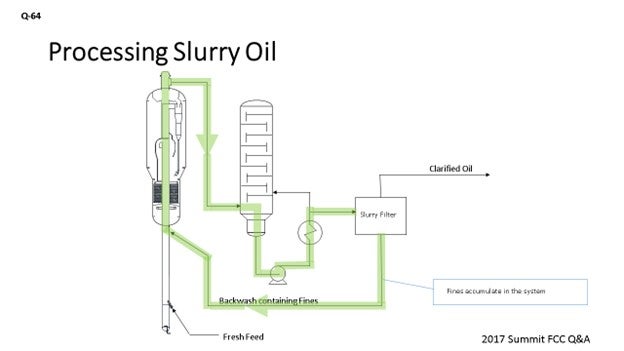
The intent of recycling the fines back into the system is to increase the equilibrium fines content in the circulating catalyst and push the smallest material out of the regenerator side. With a modern reactor termination device that is close coupled to the reactor cyclones, the ability to do this is more difficult. The fines recycled from the separator back to the riser may be directly lost again, causing fines to build up in the MF (main fractionator) bottoms circuit. An example of this issue occurred in a unit that we saw which had revamped to add in a modern slurry catalyst separator system. This particular refinery observed that catalyst concentrations measured in the slurry pumparound system increased by a factor of two with the slurry catalyst separator system in operation. The slide illustrates how fines will accumulate in the system.
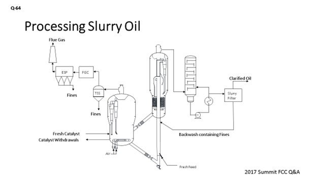
The fines have to exit from the system somewhere. Ultimately, an equilibrium will be achieved that allows fines to exit through the regenerator cyclones. With both slurries recycle and the backwash, expect increased losses of catalyst from the regen side. If no hardware is in place to collect those fines [for example, a TSS (third-stage separator) or an ESP (electrostatic precipitator)], then the fines will be seen in the stack. The fines have to come out one way or another. If you stop them from coming out of the reactor side, they will come out of the regen side.
BHARGAVA (KBC Advanced Technologies, Inc.)
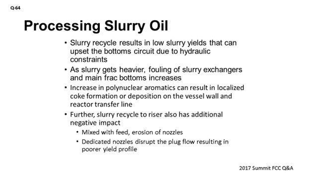
In addition to what Alex said, slurry recycling does increase conversion as slurry yields go down. We have seen a couple of situations where the bottoms circuit had problems with minimum flow. Their bottoms pumps and their hydraulic systems were not designed to reduce the slurry to that level, so these operators had to revert to not recycling slurry. As you recycle more and more slurry, the fouling on the exchangers goes up. So, you need to make sure you have enough spare capacity in the slurry pumparound exchangers to allow the operation to continue without losing availability and reliability on the unit. The PNAs (polynuclear aromatics) go up, so you will see increased localized coke formation and deposition of coke on the vessel wall, even in the reactor transfer line. Then you recycle slurry or the backwash; especially the backwash, if you want to mix that with the feed. You just have to be careful about the erosion on the feed nozzles. If it is a dedicated nozzle for the slurry, it will still affect the operation because it will disturb the plug flow of the gas and the catalyst moving up the riser. So, you could have a poor yield profile when you do this.
DINKEL [Marathon Petroleum Corporation (MPC)]
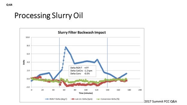
The chart on the slide is an example from one of our units that has a slurry filter. It shows the impact the unit experiences, as far as regen temperature spiking as they are pumping down that collection tank. This temperature response illustrated on the chart averages about a 4 to 5°F regen temperature increase. You see a drop in cat circulation and overall conversion during that period. This temperature increase is after we did some tuning on the system. The original control logic – when the system started up – pumped down the collection tank about twice as fast, so we were seeing as high as 15 to 20-degree swings in regen temperature spikes. The takeaway here is that, as Alex mentioned, changing out your source of the flush to the HCO is one option. What we did here was just to try to dampen out the impact on the unit. My preference is to find somewhere else in the refinery to process the slurry oil backflush material.
ALEX MALLER (TechnipFMC Process Technology)
Slurry recycle and slurry separator backwash are two very different processes with varying objectives and negative impacts. Slurry recycle is typically done intentionally for the purpose of increasing coke make to help a unit that is short on heat balance. Such units are usually processing very light, sweet feeds and are unable to meet their processing objectives without additional heat input. Slurry separator backwash is required to remove the collected solids from the slurry filter/separator to ensure their efficient operation.
Although increased coke make is the benefit of slurry recycle, it is the negative consequence of slurry separator backwashing. One remedy is to avoid ‘slurry’ from being processed with the backwash by displacing the slurry that remains in the separator housing with another material, typically HCO. Another strategy is to minimize the requirement for backwashing media, but this is typically achieved in the design stage. A well-designed slurry separator should be capable of running efficiently with about 1 vol% (volume percent) of the fresh feed flow rate as backwash. To lessen the impact on the riser/reactor, it is usually recommended to process a constant and continuous flow of backwash fluid.
Another negative factor associated with both slurries recycle, and slurry separator backwash is the establishment of a ‘fines loop’ that results in higher concentrations of solids in the circulating main fractionator bottoms circuit. Modern slurry separator systems are capable of achieving extremely low concentrations of solids in slurry oil product. Therefore, essentially all of the catalyst lost from the reactor is captured and recycled, usually to the riser. These fine particles have a high potential to be lost again and repeat the circuit.
A recent example of this phenomena involves an FCCU revamp in which an advanced slurry separator system was installed. Following it is commissioning, the BS&W measured in the slurry pumparound increased by a factor of two. The consequences are increased wear and expected reliability issues in the slurry pumparound, particularly the pumps and the control valves. An increase in the e-cat fines content, and eventually pushing the fines out to the regenerator flue gas, is the objective. Additional losses from the regenerator should be expected. Ensure that the regenerator flue gas catalyst collection systems are capable of capturing the higher quantity of catalyst. One potential mitigation for avoiding this ‘fines loop’ is to change the location of the backwash recycle. Traditionally, it has been taken into the riser. A possible alternative is to inject the backwash directly into the reactor or stripper where there is a higher likelihood that the fines will make their way into the regenerator. However, such an arrangement may have a greater impact on delta coke, which could either be a positive or negative depending on the unit constraints.
SANJAY BHARGAVA (KBC Advanced Technologies)
Recycling slurry will reduce slurry yield. Therefore, units already running at minimum bottoms rate constraint – due to hydraulic constraints – will need some design modifications in the bottoms circuit. The slurry will get heavier, so fouling in the desuperheat section in the bottom of the tower and in the pumparound exchangers will increase. Further, the increase in polynuclear aromatics can result in localized coke formation or deposition on the vessel wall and reactor transfer line.
The location of injection is also a key consideration. If the recycle is injected with the fresh feed, the catalyst fines will accelerate the erosion of the nozzles and degrade nozzle performance (more so for slurry separator backwashes). If the slurry is recycled to a dedicated nozzle (which is more typical), then the plug flow up the riser is disturbed and can result in overall poor yields.
BRYAN DINKEL [Marathon Petroleum Corporation (MPC)]
The impact of slurry filter backwash on unit operation is an intermittent swinging of the system due to slugging slurry back to the riser, which impacts the unit just as slurry recycle does. The additional carbon in the feed results in an increase in regenerator bed temperature, a reduction in catalyst circulation, and a degradation in conversion and yields. The magnitude of the impact to the unit will be dependent upon unit operation and the programming logic for the backwash sequence. The number of filters, time between backwashes, collection tank volume, and the time to pump down the backwash collection tank will determine the frequency, duration, and volume of backwash to the riser. Figure 64-1 provides an example from one of our units of the operational swing impact due to routing slurry filter backwash to the riser, which resulted in a conversion reduction of about 0.5% LV (liquid volume) for numerous hours each day and which accounts for multiple filter backwashes throughout the day.
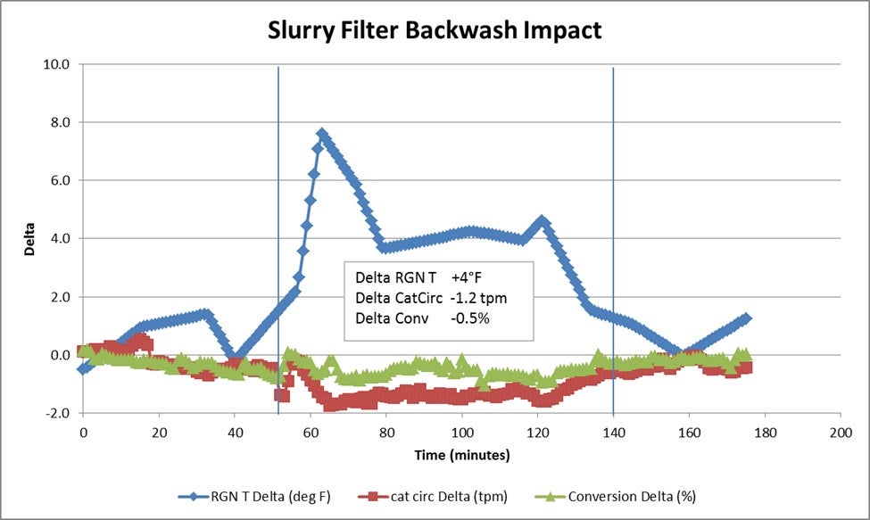
Figure 64-1. Slurry Filter Backwash Impact on Operation