Question 54: What are your options and Best Practices for routing liquids in a desalter pressure relief scenario if routed to crude fractionator? If routed to crude fractionator, how should one avoid damage caused by water?
PRICE (Fluor Corporation)
Thank you so much. The discussion of where to route the discharge of relief valves is always a great conversation, and we are going to talk a lot about what happens in the crude preheat train; and specifically, with desalter PSVs (pressure safety valves). We want to minimize the amount of liquids (especially water) sent to the fractionator whenever possible. I have a couple of pictures to show just in case some of the younger people have not ever seen, firsthand, what happens when you get water into a fractionator.
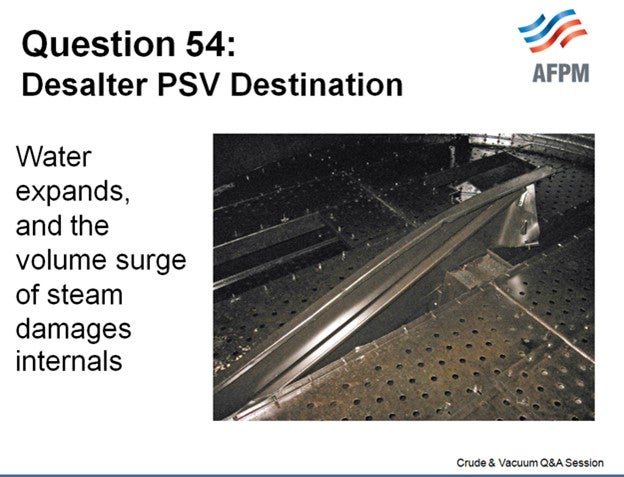
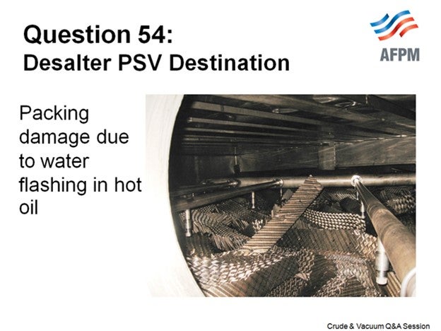
These are damaged stripping section trays, and the next slide shows damaged packing. The damage occurs when the water expands rapidly and there are huge uplift forces which damage the tower internals.
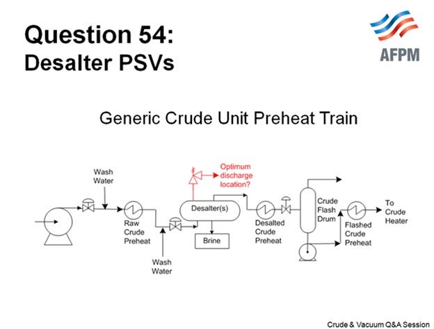
This slide is a generic crude preheat train to help us stay focused.
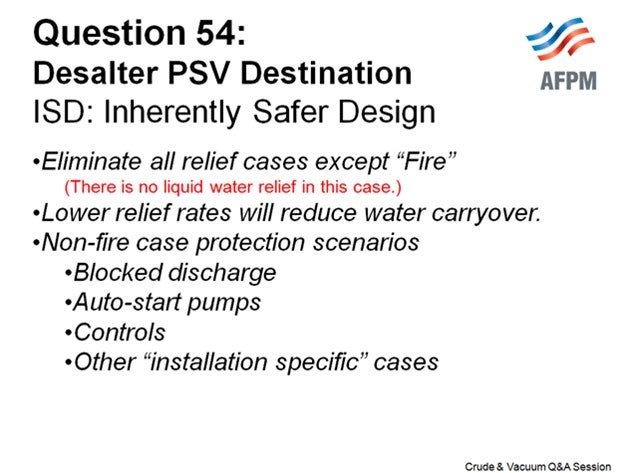
The best way to mitigate problems in your fractionator is by having an inherently safer design (ISD). The goal is to have a relief valve where only fire case relief protection is required. Within the code requirements, whenever you can lower your relief rates, you limit the amount of potential water carryover. Relief rates are very, very installation-specific and refiners are increasingly using and reviewing their control schemes, including review of their pump autostart philosophies (whether they have motors or turbines) to eliminate or reduce pressure surges that can lift the crude system relief valves.
One important factor is that the crude piping (as well as the relief valve inlet and outlet piping) must never have dead legs or pockets where water can accumulate. This is important because these “puddles” of water can be “picked up” and carried with the bulk crude flow if there is a pressure surge, even if it does not lift the PSV. The water is accelerated through the flash drum and into the fractionator, causing damage like what occurs if the desalter PSV lifts and discharges to the fractionator. One refiner calls this the tsunami effect.
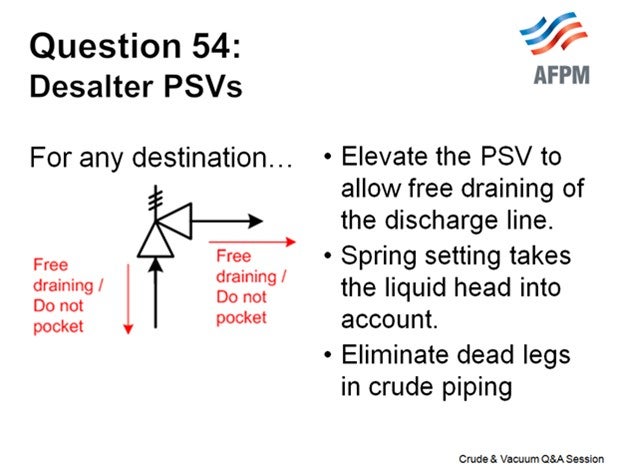
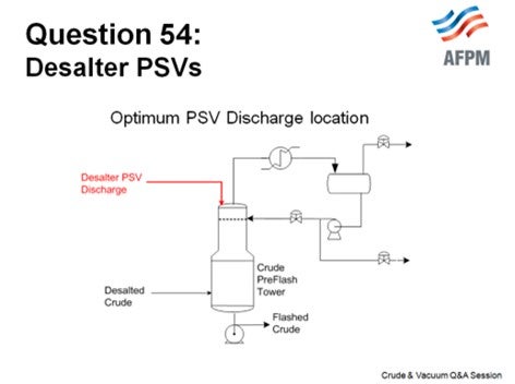
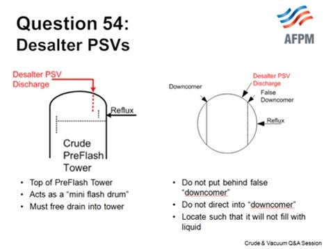
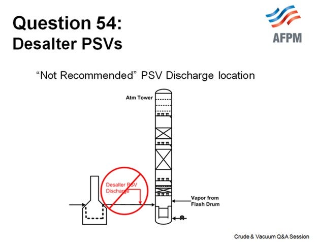
We think that the optimum location to route the PSV discharge is to the top of your crude preflash tower, if you have one. The top of the crude preflash tower acts like a mini flash drum, and the temperatures are cooler there; so, it is not going to flash quite as much or quite as hard as the main fractionator flash zone. Make sure that the routing is such that it is a top entry, so the line cannot fill with liquid and there are no restrictions in the outlet pipe.
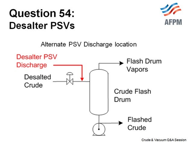
An alternate destination, if you have a flash drum (and not a tower), is the inlet of the flash drum downstream of any backpressure control valve (if present). Not everyone has a backpressure control valve to suppress vaporization, but many people do. As before, the PSV discharge line must be a top-entry connection to the flash drum inlet line.
There are PSVs that discharge to the transfer line or into the main fractionator flash zone. This is not recommended (because of the potential damage that can occur); but if you have this installation in your facility, you can begin working to mitigate the relief load by making some changes that will mitigate the impact to your tower. These changes include elimination of dead legs, engineering changes to reduce the relief load enough to allow installation of a smaller PSV, and control changes to reduce the likelihood of pressure surges.
This slide shows some recommended reading. It is a paper that was published at a recent AIChE (American Institute of Chemical Engineers) meeting. It talks about pressure surge incidents, but it also includes quite a bit about relief valves and contains additional information.
ALLRED (Suncor Energy, Inc.)
I agree with Maureen. The issue here is the water when it expands. When you have liquid water hitting these high temperature crude units, they expand hundreds of times and can wreak havoc on your internals. I have personal experience with that. It was not a desalter relief but rather some condensate that was left in a stripping steam line. When it was turned on, the condensate hit the tower and just ripped out the trays; and these were beefed-up trays. So even if you have reinforced trays, when water hits, it can still cause a lot of damage. So, the best protection against this is to design your desalter such that the only viable relief case is fire.
We had a couple of desalters in one of our crude units that were redesigned a few years ago. When they were redesigned, we increased the design pressure enough so that fire was the only viable case. We then rerouted that PSV discharge to the flare knockout drum, so we did not have to worry about this issue. We have a couple of other crude units where the PSVs are still routed to preflash drums, much like Maureen discussed.
RATHINA SABAPATHI (Kuwait National Petroleum Company (KNPC)]
Good morning. The concern is related to this. Because of the safety valve location, there are dead pockets in the line more than 300 to 400 meters (about 1312.34 ft). And recently we had a failure on this line due to the corrosion which was due to the stagnant portion of the line. Is there anything that can be done?
In addition to the pocketing, some water vapor is still coming in and condensing (liquid), causing corrosion of the line between the safety valve and the desalter. Has anyone come across this issue? How do we overcome this?
PRICE (Fluor Corporation)
I just want to clarify that I understood you correctly. It is the inlet line to the relief valve that is elevated. Typically, the liquid line to the relief valve is liquid-filled, and it is filled with crude. I do not know where it is placed; but typically, there would not be water vapor that is making it up to this area.
RATHINA SABAPATHI (Kuwait National Petroleum Company (KNPC)]
It is not the water vapor. It is stagnant crude, plus a little amount of water which is causing localized corrosion because it is stagnant. It is in the inlet of the PSVs where we had two failures. Is anyone heating up this line or keeping it hot?
ALLRED (Suncor Energy, Inc.)
I have no experience with that.
PRICE (Fluor Corporation)
Thank you for the clarification. The PSV nozzle is presumably located on the top of the vessel. The inlet line runs vertically and is not pocketed but does have some long horizontal runs. Corrosion due to stagnant sour water is one possible cause. Another plausible explanation could be trapped gases from startup and/or the slow accumulation of gases [CO2 (carbon dioxide), H2S, etc.] that are evolving from the crude. The evolved gases could create a corrosive environment at or near the PSV inlet nozzle or in the piping. The following factors are to be considered:
-
The length of the inlet line that you note is substantial, and there are likely horizontal runs in the inlet line to the PSV.
-
The desalter operation will have a significant effect on the amount of water present in this line.
-
Some crude slates will evolve more gases than others.
-
Whether you have a method in which to ensure vaporization is suppressed in the crude (pressure control of the crude charge or back pressure valve at the flash drum).
-
If suppression of vaporization is not possible, then if the PSV has a bypass, you can periodically crack it open to purge any accumulation of vapor. Periodically cracking the bypass will also purge the stagnant crude in the line as well.
An additional resource is NACE Pub. 34109, “Crude Distillation Unit - Distillation Tower Overhead System Corrosion”, which include the following statements that may be relevant:
-
Page 7: Oxygen in the desalter washwater can cause increased corrosion in the desalter itself and in the CDU preheat train.
-
Page 23: Several sources of desalter washwater (e.g., city water, industrial water, surface water, and possibly vacuum tower overhead condensate) contain varying levels of oxygen. This oxygen can lead to pitting corrosion problems in the desalter washwater and effluent brine systems. Oxygen is also carried into the CDU distillation tower overhead systems by entrained water with the crude oil leaving the desalter. Besides causing pitting corrosion, oxygen can react with H2S to form elemental sulfur, which can cause fouling and/or corrosion. Oxygen can also react with sulfur to form acid gases such as SOx. Sulfur dioxide (SO2) and sulfur trioxide (SO3) are the precursors to formation of H2SO3 (sulfurous acid) and H2SO4 (sulfuric acid), respectively. The potential negative effects of oxygen are reduced by limiting the allowable amount of oxygen in the desalter washwater to less than 1 ppm. Oxygen scavengers are occasionally used to further limit oxygen’s effects. One user reported that he specifies a maximum oxygen concentration of 20 ppb (parts per billion) in the desalter washwater. When evaluating the use of an oxygenated water source for desalter wash, the benefits of increased washwater are normally weighed against the costs associated with corrosion, water purchase, and increased loading on the wastewater treatment plant.
LUIS GORDO (Amec Foster Wheeler)
Typically, desalter PSV relief is routed to the crude tower or preflash drum. Desalters may or may not be designed for the shutoff pressure of the cold crude charge pumps. It is generally a question of balancing the greater costs involved in designing for a high design pressure against the operational disadvantages caused by desalter safety valve occasionally lifting and not reseating properly during operational upsets. As a minimum, the desalters are always provided with a safety valve to protect against a fire case. If only designed for fire case, water damage should not be of concern. When the PSV is designed for a blocked-in case, mitigation steps should be taken, starting by designing crude or preflash tower internals to withstand increased uplift forces (2 psi minimum). Other strategies include:
-
Shutting off the water injection to the desalters and
-
Pinching back on the crude charge pump VFD (variable frequency drive) or turbine speed (if applicable)/shutdown pumps to reduce operational upset.
ANDREW SLOLEY (CH2M HILL)
Desalter PSVs may either release to a disposition inside the crude unit or outside the crude unit. Based on refinery surveys, the industry has nearly a 50/50 split of dispositions. A survey of crude units shows the following dispositions:
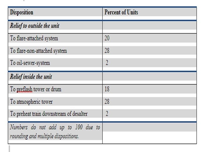
When the PSVs discharge to a downstream tower, they may either enter the tower flash zone or the tower liquid sump. In either case, trays should be mechanically strengthened to resist damage from flash vaporization of water.
The trend is to move away from discharge to blowdown systems without flares (flare-non-attached). Today these systems normally discharge to atmosphere through a blowdown drum.
MAUREEN PRICE (FLUOR)
The destination for the desalter relief valve discharge continues to be a good topic of discussion. Best Practices involve inherently safer design (ISD) where only fire case relief protection is required, and that resultant relief load will not result in liquid water to the fractionator.
Non-fire case overpressure protection is required when the mechanical design pressure of the desalter(s) is less than the achievable pressure during upsets, such as a blocked discharge. The magnitude of overpressure, relative to the code allowable, dictates the required relief valve capacity. Lower relief rates, as determined in accordance with code requirements, may reduce or avoid desalter water carryover and the severity of the upset.
Desalter relief valves, which can carry liquid water, have been a common cause of tray damage due to the sudden expansion of any water present.
Discharge of the desalter PSVs are commonly routed to the following locations:
The Atmospheric Tower Flash Zone: It is not recommended to route the desalter PSVs to the atmospheric tower unless the only case is fire protection, although there is at least one Southern California refinery that has the desalter PSVs discharging to a common header that connects to the transfer line.
A Dedicated Blowdown Drum to Collect Liquid PSV Discharge Streams: A dedicated blowdown drum (VENTED TO A CLOSED FLARE SYSTEM) is the safest option with the least impact on unit operations during a relieving scenario but has the highest capital cost due to the large size required.
A Preflash Drum: Discharging a preflash drum is considered an optimal solution. It is lower cost since there frequently is already a flash drum; it is a minimal operational upset scenario as the drum contains enough volume for water vapor to flash without a sudden surge in pressure; there is already a pump to allow emptying of the relief liquids; and, the downstream exchangers will ensure the gradual heating of the desalter liquids (which will likely contain water at some point) by the preheat exchangers to avoid sudden water vaporization.
The Preflash Tower: Discharging the desalter PSVs to a preflash tower is acceptable; provided that the discharge is to the upper section of the tower, there should be no problem with tray uplift. Discharging to the flash zone carries the same risk of tray uplift as routing to the atmospheric tower flash zone.
Other key design parameters to mitigate operational concerns are that:
-
The desalter PSV inlet and outlet lines are free-draining (not pocketed) to ensure that liquids cannot accumulate anywhere;
-
The entire crude preheat system is designed without dead legs so that water cannot accumulate anywhere;
-
Appropriate flow and/or pressure control of the crude charge to the unit;
-
Operational review is performed on the Autostart controls on spare charge pumps and the use of variable speed drives (turbine or motor).
Fluor recommends the following paper as an excellent reference on the subject: “More Tower Damages Caused by Water-Induced Pressure Surge: Unprecedented Sequences of Events”1, which is a classic on the subject. It presents the case studies and the lessons learned, as well as several recommendations which we endorse.