Question 52: What challenges do you face for implementing safety-instrumented systems that result in closure of the FCC slide valves?
FOOTE (CHS Inc.)
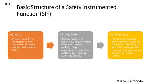
Safety-instrumented shutdown systems have been used in many refining processes. Regardless of whether it is applied, the basic structure of a safety-instrumented function is as follows: First, there are initiators. These are pressure, temperature flow, or level transmitters that sense a condition that requires some type of action. These transmitters can also be used for control, but they should be hardwired to the SIS (safety-instrumented system) and then passed through to the control system. The second piece is the SIS logic solvers. These are electronic hardware that receives information from sensors which change the state of the outputs based on the configured logic. These systems are separate from the normal everyday control. Typically, these systems have built-in redundancy to improve reliability. The third piece is the final elements. These are the elements – including valves, solenoids, or relays – that receive the signal from the logic solver and then change the state. Normally, these are not the same elements that are used in everyday control; that is, you have a control valve, and then you have a chop valve downstream of it.
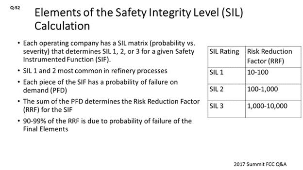
Each operating company has a safety integrity level (SIL) matrix that, basically, has probability on one axis and severity on the other axis to determine if SIL 1, 2 or 3 is required based on the hazard associated with the pertinent safety instrument and function. So, each functional piece of the safety-instrumented function has a probability of failure on demand, and the sum of the probabilities of failure on demand gives us a risk reduction factor. The table on the right side of the slide shows the risk reduction factors required for each of the different SIL ratings. SIL 1 and SIL 2 are the most common ratings in the refining industry. For example, I think we only have one SIL 3 to safety-instrumented function in our refinery and it is not in the FCC.
Breaking down the probability of failure on demand based on the functional piece of the safety-instrumented function are the sensors. Two-out-of-three voting is generally configured, so not all sensors need to be functional. Pressure transmitters can get plugged out, but they are generally reliable. Also, the hardware and logic have built-in redundancy, so they are very reliable, too. It is the final elements, though, that sit in one state and are then required to change that state. Many times, four out of four valves – or five out of five valves – are required to close to bring the unit to a safe state. Therefore, 90 to 99% of the risk reduction factor is due to the probability of failure on demand of the final element. So, if you are trying to improve the risk reduction factor to get to the SIL rating you need, you should concentrate on the final elements.
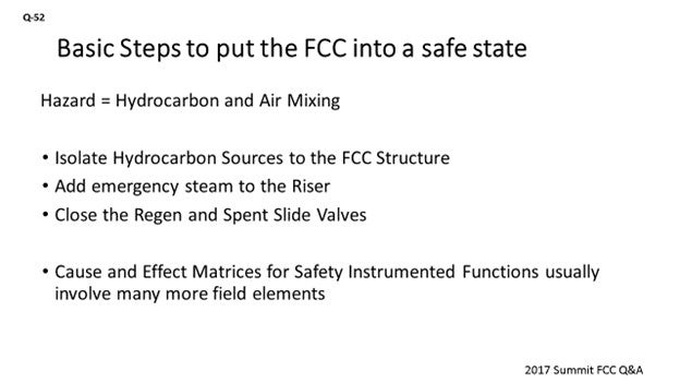
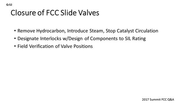
The hazard associated with an FCC is obviously hydrocarbon and air mixing. The basic steps to put the FCC into a safe state are: First, isolate the hydrocarbon sources of the FCC structure; then, add emergency steam; and finally, close the regenerated and spent slide valves to stop circulation. It is important to also realize that your cause-and-effect matrix might have many different functions. You might trip compressors, close MOVs (motor-operated valves), or pulse controllers to 0% output, for example. Not all of those functions are part of the SIL calculation, but they are the essential pieces.
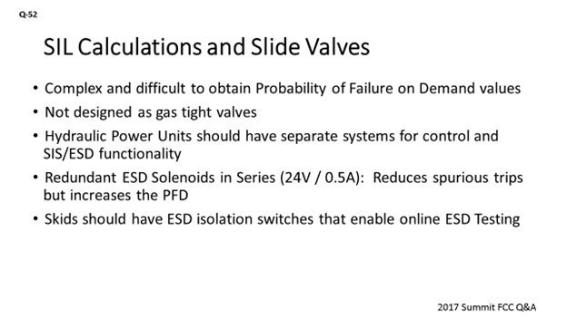
For slide valves, there is some complexity when it comes to SIL calculations. First of all, there are complex pieces of equipment that comprise the slide valve system. You have accumulators, solenoids, and other components that make it very difficult to obtain probability of failure on demand values for these valves. Also, realize that these valves are not gas-tight valves. We should always assume that they leak. So, it is only through isolation of hydrocarbon, adjusting the pressure balance, and the introduction of steam that we are able to control what and how much leaks from these valves. Modern hydraulic power units should have separate systems from an SIS and the ESD (emergency shutdown device) for control and functionality. As I said, your ESD accumulator is separate from the control accumulator and all the controls. Most ESD systems rely on redundant solenoids – or most slide HPUs’ (hydraulic power units’) redundant solenoids – to get full hydraulic accumulator pressure to close the slide valve. They do this very quickly, usually within five seconds. The series arrangement of the solenoids decreases the spurious trips but increases the probability to failure on demand, because both of those solenoids have to open. So, it is important to account for the configuration when calculating the PFD (probability of failure on demand) for that slide valve. Also, your skid should have an ESD isolation valve which will allow you to test those solenoids online; because in my opinion, the most common failure for these slide valve skids is probably the solenoid not opening. Next, realize that your SIL hardware has limits. You can only power it to 0.5 amps. If you exceed those power limits, you will then need to consider the external power source in your probability of failure.
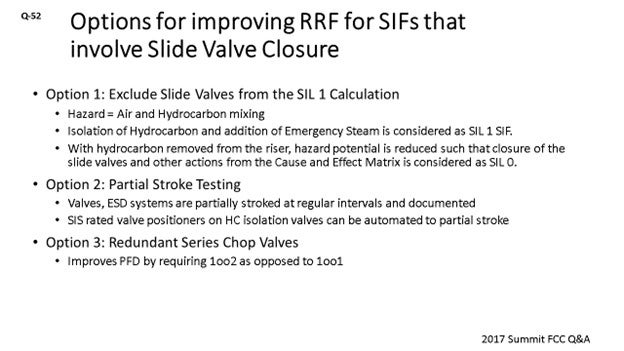
Next, I will discuss the options for getting your slide valves to pass a SIL calculation. First, remember that the hazard is hydrocarbon and air mixing. So, if you can isolate hydrocarbon and add emergency steam as your SIL 1 function, hydrocarbon has removed from the riser and the hazard potential is reduced. The closure of the slide valve and other actions from the cause-and-effect matrix can be considered as a SIL 0 function.
A second option is partial stroke testing. Valves and ESDs are partially stroked at regular intervals to confirm that they are working, and that the procedure is being documented. The SIS valve positioners on control valves can actually do that automatically and record it. It is important to note that with partial stroking, you can get a ‘slide valve to safety-instrumented’ function that involves the closure of the two slide valves to pass. But typically, you have to do partial stroke intervals of about four to eight months or so.
The third option is to focus on redundant series chop-out. You need to make sure that your hydrocarbon sources move from a one-out-of-one opening or closing to one-out-of-two. RRF is improved if you have this. It is relatively easy to apply the approach to hydrocarbon control valves, but it is very hard to do it to slide valves.
Some refiners have the luxury of having two slide valves in their standpipe, so they can operate one out of two and close the other as needed. However, most refiners only have one valve at their disposal. Within CHS, we consider the isolation of hydrocarbon to the FCC structure and introduction of steam to the riser as the SIL 1 function. The closure of the slide valves is an SIL 0 function. We do have design standards for hydraulic power units and try to meet these Best Practices, as we discussed earlier. Within the past five years, both of our FCCs have been upgraded to the right HPU and actuator systems to meet these standards when we have used two different HPU manufacturers.
DINKEL [Marathon Petroleum Corporation (MPC)]
I agree with what Darin just said, as far as the details and where to put the unit in a safe state. But within Marathon, we have taken a little different approach by following RAGAGEP (Recognized And Generally Accepted Good Engineering Practices) and defining that within our own internal application standard. We are specifying what interlocks are required on our FCCs without necessarily having to go through the full LOPA (Layers of Protection Analysis) process on those interlocks. We do specify individual components to be designed, installed, and tested on a frequency that is higher, as if it is a higher integrity SIL.
I want to point out that we also follow a “trust but verify” approach. Procedurally, we require that if we have a unit trip, Operations must go out within a very short period of time to verify that 1) the valves that are supposed to close have closed (e.g., slide valves) and 2) other items have opened as intended, such as the emergency steam valve to the riser.
MALLER (TechnipFMC Process Technology)
I agree with both of the responses so far. From a design perspective, at TechnipFMC, we do not consider the slide valve closure as the final element in the safety system. We require that parallel actions occur that put the unit in a safe place. There is also the critical step of having someone go in the field and verify that the valve is closed; or if not, make it close.
J.W. “BILL” WILSON (FCC Consultant)
I have a question about partial stroke. If anyone on the panel or in the audience does that, how far do you stroke the slide valve? I mean, the slide valves are unique in that they are one of the few places where your regular control valve is also your isolation valve. If you do partial strokes, how far do you stroke them?
FOOTE (CHS Inc.)
I can answer that question. We do not really partial stroke. All we do is test the ESD (emergency shutdown). If those ESD solenoids open, you will get full hydraulic accumulated pressure to that actuator. It will close the valve. So, we do not do a partial stroke, in the sense of removing the valve. We are just isolating the hydraulics when testing the solenoids so they will open.
W. LEE WELLS (LyondellBasell Industries)
We are one of the lucky refineries whose FCCU has dual slide valves; so, we partially stroke with one while we control with the other one, and then we swap them. We stroked the slide valves enough to still have the same pressure differential. We end up closing it down to somewhere around 40 to 50% open.
I will also just echo the comments about the field verification because we have experienced our feed MOV not closing completely when it was activated, as have some other sites I know. The feed MOV is supposed to trip and take the feed out of the riser. If it does not happen, you will end up filling up your riser with oil. That is a bad situation to be in. So, definitely put field verification on your list.
WARREN LETSZCH (TechnipFMC Process Technology)
I am curious. When you have a high temperature excursion in the regenerator around 1600°F and everything gets hot, does anyone worry about whether the guides in the slide valves might get warped. Do you check the slide valves after such an excursion, or do you just hope everything is right? Or is this not a problem with any of your designs?
FOOTE (CHS Inc.)
We have not had any shutdowns associated with high temperature yet, but we do have temperature initiators in the regenerator. I think at 1500°F, we have an hour to get it lower. At 1600°F, there is an immediate stop in the circulation. We have had a couple of excursions. We did not really check the slide valves, because they seem to work okay.
TRAGESSER (KBR)
I will just add that in the scenario you just described, the low slide valve pressure differential would trip and close the slide valve. If you have flow reversal, you will then get a chance to see if the slide valve works.
DARIN FOOTE (CHS Inc.)
Safety-instrumented shutdown (SIS) systems are used in many refining processes. Regardless of the process or equipment where it is applied, the basic structure of a safety instrument system includes:
-
Initiators (Sensor Devices): These are pressure, level, flow, temperature, or other transmitters which sense a condition that requires action.
-
SIS Logic Solvers: This is the electronic hardware that receives information from the sensors and changes the state of outputs based on configured logic. These systems are separate from the controllers and hardware used in everyday control. Typically, these systems have built-in redundancy to improve reliability.
-
Final Elements: These are field elements including valves, solenoids, relays, etc. that receive a signal from the logic solver. Normally, these elements are not the elements used for everyday control, i.e., the control valve (everyday control) would be in series with a chop valve (SIS).
Systems are designed to meet a specific safety integrity level (SIL). Each operating company has a risk-based matrix specific to the company or site. This matrix has severity on one axis and probability on the other axis. High severity and high probability score the highest. Based on this ranking system, the company sets the SIL rating at SIL 1, 2, or 3. SIL 1 and 2 are the most commonly found in typical refinery processes. SIL 3 is the highest and is not common to refinery applications. The hazard analysis (HAZOP, PHA, LOPA, etc.) establishes the required SIL for each safety-instrumented function (SIF).
SIL varication calculations are required to ensure that the hardware used in each SIF has the capability to achieve the required SIL from the hazard analysis. The result of these calculations generates a risk reduction factor (RRF). The RRF is dependent on the probability of failure on demand (PFD) of all the components in the system.
Table 52-1 lists the industry-required safety-instrumented risk reduction factors (RRF) for the three major SIL ratings.
Table 52-1. RRFs Required to Achieve Various SIL Ratings
|
SIL RATING |
RISK REDUCTION FACTOR (RRF) |
|
SIL 1 |
10 - 100 |
|
SIL 2 |
100 - 1,000 |
|
SIL 3 |
1,000 - 10,000 |
Figure 52-1 illustrates a scenario for a typical slide valve pressure differential interlock protecting the Rx/regen (reactor/regenerator) system from hydrocarbon and air mixing should a pressure reversal occur. In this example, the SIL calculation only considers removing hydrocarbon from the Rx/regen system to mitigate the risk of explosion. Specifically, removal of hydrocarbon is considered an SIL-rated function and the closure of the slide valve(s) and addition of emergency steam is not SIL-rated. Three pressure transmitters monitor the dP (∆P; delta pressure; pressure differential) across the slide valve. If 2oo3 logic senses a low pressure, the logic solver will send a signal to four final elements to block in hydrocarbon flows to the Rx/regen system. For this example, the interval of testing is 54 months.
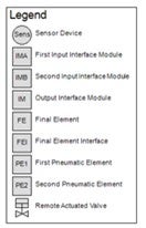
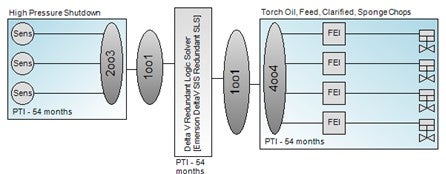
Figure 52-1. Safety-Instrumented Function - Low Slide Valve dP
Figure 52-2 is a graphical representation of the percent contribution to PFD based on functional pieces of the SIS system shown in Figure 52-1. As shown, most of the failures on demand are due to failure of final control elements. In this example, all four valves must close to mitigate the risk of explosion. This 4oo4 action results is a high likelihood of failure on demand.

Figure 52-2. Probability of Failure on Demand Contribution by Functional Piece
To improve an SIL rating, we must improve the PFD for the final elements, which can be done in two ways. First, adding partial stroke testing intervals to these essential elements can verify that the valve is functioning properly. If partial stroking is practices at intervals during the run, then the PFD will go down and the RRF will go up. Second, adding redundant chop valves brings this to 1oo2oo4, which increases the RRF. Table 2 shows the cumulative effect of both of these changes to the base configuration shown in Figure 52-1.
Table 52-2. Ways to increases Risk Reduction Factor (RRF)
|
|
Base Case: 4oo4 valves closing |
4oo4 valves closing with partial stroke testing |
1oo2oo4 (Redundant chop valves in series) |
|
PFD Average (Sensor) |
5.23e-04 |
5.23e-04 |
5.23e-04 |
|
PFD Average (Logic Solver) |
2.51e-04 |
2.51e-04 |
2.51e-04 |
|
PFD Average (Final Element) |
9.13e-02 |
5.38e-02 |
1.20e-02 |
|
Achieved RRF |
11 |
18 |
78 |
|
SIL Rating Achieved |
SIL 1 |
SIL 1 |
SIL 1 |
The example shows the difficulty of using normal control elements as functional pieces of SIS logic. Slide valves present a particular challenge to these calculations due to their complexity of components. The Best Practice is to design slide valve hydraulic systems such that the valves have an SIL 1 rating, regardless of whether or not they are included in the SIL calculation. If slide valves are included in the SIL calculation, the following should be considered when determining the PFD of slide valves:
-
Actuator Hydraulics: The control side of the hydraulic skid and SIS/ESD side should be separate with independent hydraulic accumulators.
-
Redundant Solenoids: Solenoids are typically used as the final element to send full-system hydraulic pressure to close the slide valve. HPU manufacturers often put redundant solenoids in the hydraulic ESD configuration. Though this reduces spurious trip potential, it increases the PFD as both solenoids are required to change state to initiate the ESD sequence. Also note that logic solver outputs have power limitations, so power injection or interposing relays may be required to properly actuate the solenoids on the HPU skids. This situation introduces another point of potential failure.
-
Provisions should also be made to perform ESD testing of the slide valve skid on the run. This practice has the same effect as partial stroke testing of a chop valve, typically requiring SIS logic, as well as an ESD bypass valve at the slide valve skid. Generally, partial stroke testing intervals of six to eight 8 months are required to achieve an RFF of 10 – which is required for an SIL 1 rating – on a 54-month test interval.
-
Slide valves are not designed to be gas tight when shut off. The best-case scenario is a catalyst tight shutoff. However, the reality is that during the run, even a catalyst tight shutoff is difficult to achieve.
In summary, as a company, you should carefully examine your cause-and-effect matrix for SIS. Reduce the resultants to a few essential actions to mitigate the risk. Once the number of elements is reduced, focus on these final essential elements to improve your risk reduction factor.
BRYAN DINKEL [Marathon Petroleum Corporation (MPC)]
The fundamental key to placing an FCC into a safe state during a trip is to keep the hydrocarbon and air separated. In order to accomplish this division, isolate hydrocarbon (feed) sources, stop catalyst circulation, and introduce steam to the riser. Isolation valves with tight shutoff ratings for the feed are standard offerings from valve suppliers. Reliable solenoid valves and proper system designs ensure that steam valves will open, and hydrocarbon valves will close on demand. Valve suppliers can provide probability of failure on demand (POFoD) numbers from industry-published documentation for use in evaluating an SIS (safety-instrumented system) with the LOPA.
The third component of putting the FCC into an isolated state is the slide valve, which is a complex piece of equipment that provides a challenge for getting a POFoD. Slide valve manufacturers hesitate to provide this number due to the fact that the numerous components in the valve and actuator system can fail. Within Marathon Petroleum Corporation, we utilize the Recognized and Generally Accepted Good Engineering Practice (RAGAGEP) approach pertaining to slide valves, relying on licensor expertise and industry experience. As such, we designate trips involving the slide valves as interlocks. We do require design of all components to be SIL-1 or higher and to have a required closing time of less than 30 seconds. We also require a field verification step to confirm that the feed is isolated, and the slide valves have moved to the fully closed position.
ALEX MALLER (TechnipFMC Process Technology)
Slide valves are critical for the safe and reliable operation of most FCC units. Generally, when they are required to close, it is to prevent the mixture of hydrocarbons and oxygen, either from hydrocarbon ingress into the regenerator or air ingress into the reactor. The closure of the slide valve is initiated by low pressure differential as measured across the valve by purged pressure instrument taps. The timing for the closure must be fast for it to be effective. To ensure the reliability of the pressure differential instrument reading, and to prevent nuisance trips, two-out-of-three voting by three separate instruments, each with dedicated taps, is recommended by Technip. Another measure to prevent nuisance trips is to use a pressure-differential controller which is provided to take over control and begin closing the slide valve when low dP is detected.
Although these features are critical for the safe operation of the FCC, they cannot be tested regularly without resulting in major upsets to operation. Additionally, the slide valves are functioning in a very aggressive environment and are prone to mechanical damage, which may result in their failure to close or inability to provide adequate seal when closed. Therefore, when the slide valves are asked to close, other actions should happen at the same time; for example, diverting feed from the riser. Ultimately, robust operator training and procedures are required to handle these situations in case the slide valves do not function properly. During every turnaround, the slide valve should be overhauled, and the emergency shutdown actions tested.