Question 49: What are the criteria for levelness during dense loading of a catalyst bed? What are the preferred monitoring techniques, and what is the best approached to correct an uneven bed profile if it is detected?
WATKINS [Advanced Refining Technologies (ART)]
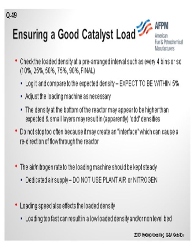
Really, it is not so much that you want to maintain a definite level bed, but what comes with that is making sure you are truly loading your reactor correctly and that you have an even distribution of densities through your entire bed. We also recommend that you check loading densities at some prearranged interval. Initially, it may be 10 or 15% of the start-of-run and then every 25% throughout the load until you are finished. This will give you a baseline to confirm that you have made a level bed, maintained the right density, and avoided issues. Sometimes a sign of a density change is actually an indication that the bed may not be level. Certainly, make sure that is handled.
Also consider what will throw off the levelness of the catalyst bed in your reactor. For instance, make sure your loading machine is using a dedicated air supply. Do not use plant air or plant nitrogen because they vary and can drop out on you. So now you have a machine that is making a variable density. It is loading more to one side of the reactor than to the other. Using a dedicated source of gas will also help ensure that you have maintained a level bed and are loading it at the correct rate. Keep and maintain an even speed on your loader, which will also help you avoid pushing catalyst to the walls. You will have higher catalyst on the walls and the center of the bed making a dip. Or the opposite effect: You are loading too slowly, and it may all be going to fall to the middle of your reactor. So first make sure that the catalyst is actually loaded correctly.
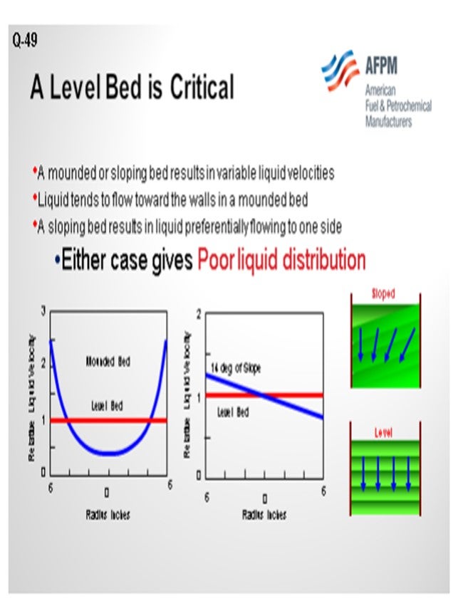
Regarding the point of what qualifies as a level bed, this is concern because a mounded bed will create variable space velocities. You have created something that is mounded in the middle; it is high density in the middle of the reactor. So your lowest space velocity would be in the middle and the highest space velocity would be along the walls. The oil is not evenly distributed through your entire bed. It is not contacting all of the catalyst at the same pace. It is the same situation if you have a slope in the reactor. The chart on the right indicates that a 14° slope versus a level bed. On one side of the reactor, the oil is actually moving through a lot faster than the other. In this case, we are getting some maldistribution. It is not efficient.
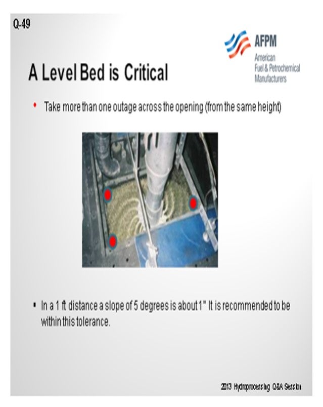
So why do we say that a level bed is critical? The way to ensure that you are maintaining a level bed is certainly to take more than one outage. If you are doing taking outages with a tape measure while your loading company is there, make sure they take more than one measurement from the same place along your tray opening or from the same spot at the top. Do not have them measure from different locations. Make sure it is always done the same way.
To give you a frame of reference for this scenario, we recommend that about a 5° slope is tolerable. So, if you have a one-foot opening, you should be able to see no more than a one-inch difference. If you have 30 feet on one side, then it should be 30 feet, give or take an inch, one foot away from that. This distance is within our target recommendation for levelness. If it is not level at that point, you will have to consider how much you are out of level. If you are exceeding 10% or so, you will have to go in and vacuum it out until you are level. We never recommend actually going into that reactor on a dense-loading system because you will only be raking a layer of sock loaded catalyst over dense-loaded, thus creating the same issue except that it will look flat from the top.
LIOLIOS (DuPont Clean Technologies)
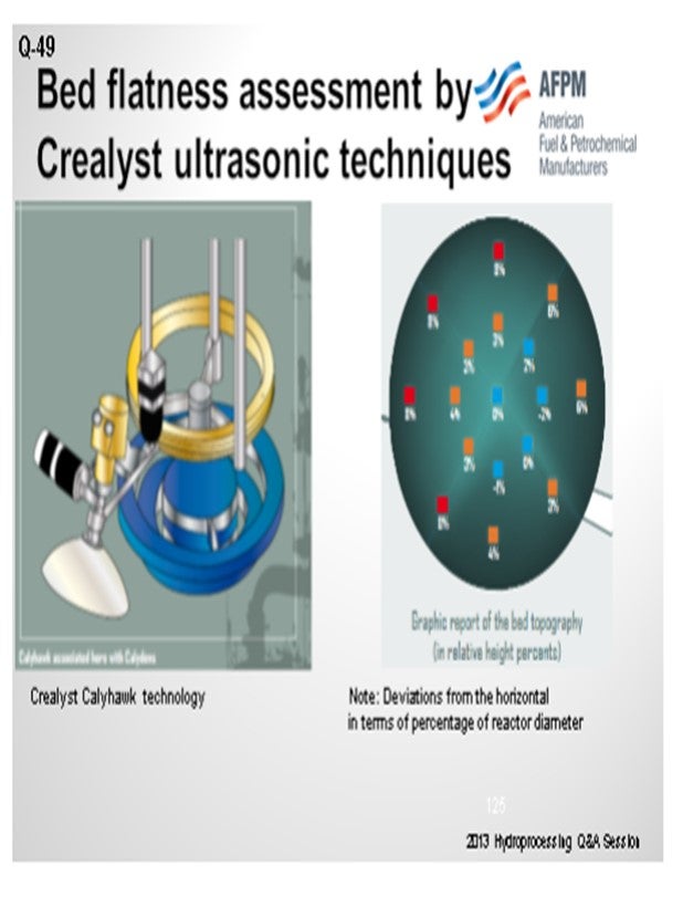
All I want to add is that our customers have had good success using the Crealyst ultrasonic method. As you can see, it actually provides a graphical representation of your accomplishments in certain intervals.
SIVADASAN (UOP LLC, A Honeywell Company)
UOP typically specifies a slope of 6° as the maximum acceptable slope for any significant part of a catalyst bed. If the slope is more than 10°, the catalyst must be vacuumed out and the bed leveled before continuing with the loading. If the slope is between 6° and 10°, a judgment will have to be made on the acceptability, depending on how large of an area which has been affected and how high in the bed that un-levelness occurs.
JON PRUDHOM (UOP LLC, A Honeywell Company)
Glenn, you said you have an ultrasound level indicator?
LIOLIOS (DuPont Clean Technologies)
It is not ours. Another company provides that technology.
JON PRUDHOM (UOP LLC, A Honeywell Company)
How easy is that to set up? For instance, if the bed is 20 feet high, how well does the tool work?
LIOLIOS (DuPont Clean Technologies)
Our technical service guy, who was there with the customer, said that it worked very, very well and was very easy to handle. That is all I know; I have not seen it myself.
JON PRUDHOM (UOP LLC, A Honeywell Company)
And you can see through the dust and everything that is there?
MUKESH PATEL (Reliance Industries Ltd.)
During sock loading, at what frequency is the leveling to be done and density measured?
WATKINS [Advanced Refining Technologies (ART)]
For sock loading, we recommend the same frequency. You are going to go in about the first 10% to make sure it is level and do it every 25% to take an outage. Usually when they take that outage, it is when they are raking it to make sure it is level at that point. At sock loading, you have a lot more control over the bed level. Assuming you have a good loading company that is actually spending time moving that sock around, it should be mostly level.
BRIAN WATKINS [Advanced Refining Technologies (ART)]
For a level catalyst bed, ART recommends ensuring a slope of 5° or less be maintained throughout the loading. This corresponds to a difference in catalyst bed height of 1 inch over a 1- foot distance across the bed. A slope in excess of 10° needs to be corrected by vacuuming out catalyst down to a level bed, and then restarting the loading process at the corrected dense loader settings. It is not recommended that the unlevel bed be raked or pushed around in order to level it. This can lead to variable loading densities, which may lead to uneven gas and liquid flow.
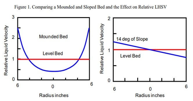
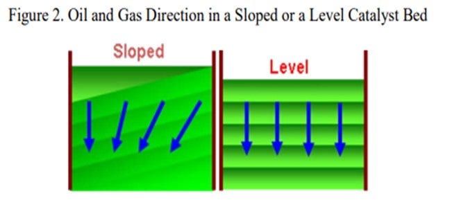
6 6 Relative Liquid Velocity Mounded Bed Level Bed Relative Liquid Velocity 0 6 6 Radius inches 1 2 0 Level Bed 14 deg of Slope Cold flow modeling shows that the oil and gas tends to flow along the slope of the catalyst bed as shown in Figures 1 and 2. For a mounded catalyst bed, the liquid velocities are higher at the walls than in the center of the bed; and for a sloping bed, the higher velocities are towards the downside of the slope. These figures clearly demonstrate the importance of a level catalyst bed to maximize catalyst utilization.
As bed densities are calculated, they should be compared to the expected density on the catalyst loading sheet. Normal differences are expected to be ± 5%. If the density varies by more than 5%, carefully recheck the calculation of the density. Verify that the bed is level since this will affect the outage and density. The dense loading machine should be adjusted as necessary to maintain an even, level bed and achieve the targeted density.
A few key items for measuring the outage:
• Check outages and bed levelness at each loading pause.
• Always measure from the same reference point.
• Always use the same measuring tape.
• Use at least two points across the bed for an outage.
Outages should be taken at reasonable intervals during the loading. Typically, an outage may be taken after 10%, 25%, 50%, 75%, 90%, and a final outage are good places. The depth of the bed or layer will determine if these outage points should be different as the loading should not be stopped too frequently for outage checks.
Refinery operations and the loading contractor should discuss how to handle TI (temperature indicator) installations. TIs should be removed prior to loading and then reinstalled when the dense loader is within 6 feet of the TI in order to minimize shadowing caused by TIs. This shadowing effect can create areas of lower density within the catalyst bed, causing an undesired redirection of flow or possible hot spots.
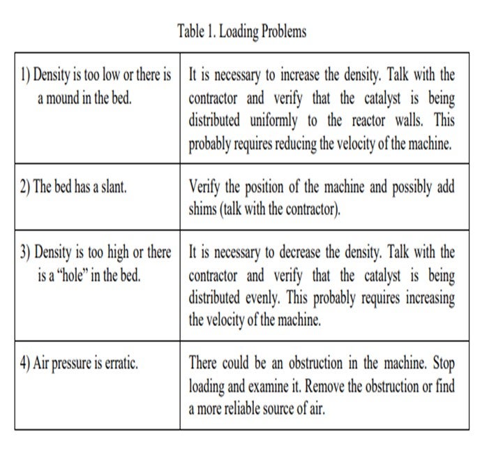
It is important that the dense loading machine be set properly. Shimming the loader may be required in order to obtain a level bed, and it is important for the loader to be centered in the manway. Table 1 lists some examples of problems encountered while loading and suggestions on how to correct them.
GLENN LIOLIOS (DuPont Clean Technologies)
DuPont concurs with the responses given by the other panelists. It should be noted that very valuable answers on this topic can also be found in previous transcripts, especially the ones found in the 2005 NPRA Q&A.
When assessing bed levelness, DuPont uses as criteria an acceptable bed level differential within +/- 0.015 x bed diameter. DuPont also recommends that the bed levelness should be evaluated every 4 feet by a skilled loading technician. However, this frequency has to agree with the dense loading schedule.
Although it is very important to have refinery engineers with expertise in monitoring of catalyst loading, it is crucial to engage an experienced dense loading company to guarantee success of this operation.
DuPont’s view on Best Practices of good monitoring of the dense loading includes:
• Prior to loading, conduct a field lab density test. This test should be conducted by an experienced dense loading technician.
• In the field, confirm the catalyst dense loading density target, update the loading diagram accordingly, and agree on the monitoring protocol and loading plan.
• Ensure consistent monitoring, maintain reliable loading records, and update loading diagrams accordingly.
• Maintain a continuous and uniform catalyst feeding rate to the dense loading machine.
Good assessment of the bed levelness by outage measurement is limited to the skill of the person performing the measurement, the manway space available, and the quantity and reliability of the measurements that can be done. DuPont recommends the use of ultrasonic technique for assessing the flatness of the bed. This technique offers superior characterization of the bed topography, resulting in more meaningful information to properly adjust the dense loading machine. We would like to thank Crealyst for their valuable input on its ultrasonic technology for density measurements.
IsoTherming® reactors are much more forgiving than conventional technologies, with regard to gas/liquid maldistribution, due to channeling caused by poor catalyst loading. In trickle bed reactors, channeling may cause portions of the catalyst to experience hydrogen starvation which may result in hot spots and shorter cycle lengths. In IsoTherming® reactors, the catalyst is completely wet with soluble hydrogen in oil. This leads to more uniform catalyst utilization and lower likelihood for hot spots caused by hydrogen starvation.
RAJESH SIVADSAN (UOP LLC, A Honeywell Company)
UOP typically specifies a slope of 6° as the maximum acceptable slope over any significant part of a catalyst bed. If the slope is less than 6° at all points within the bed, then the loader should still be adjusted as necessary to reduce slope further; however, the catalyst need not be vacuumed. If the slope is more than 10° over any significant part of the bed, the catalyst MUST be vacuumed down to a level bed before continuing. A useful indicator is no more than 1" of maximum bed height differential per foot of reactor radius.
If the slope is between 6° and 10° at any point within the bed, then a judgment needs to be made as to the acceptability of the bed. The bed acceptability will depend on how large an area is affected and how high in the bed the unlevelness occurs: the higher in the bed and the greater the affected area, the worse the out-of-level condition. A dense loaded bed should never be raked out to level.
DAVID WILKINS (Petroval LP)
With regard to “criteria for levelness”, with a maximum slope acceptance of 6˚, maximum density and good grain orientation will still be achieved. A minimum of five “bed checks” are required to monitor catalyst bed densities and levelness. It is recommended to utilize a loading system that is capable of delivering different volumes of catalyst to different areas of the reactor to properly correct an uneven bed profile if necessary.