Question 35: What are your major parameters and mechanisms that affect coker furnace fouling? Are there known effects from some specific crude properties? What are typical fouling rates, and how can they be minimized?
SOLOMON (Athlon Solutions)
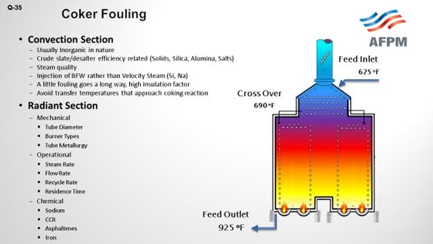
Favorable coker margins have caused all refiners to take a good look at the coker furnace fouling and how we can extend our run lives and get more out of them. Two areas obviously within the furnace – the convection section and the radiant section. Look at two different ways of what is going on to understand what parameters and mechanisms are causing fouling. In the convection center, we are mainly looking at organic solids – obviously, the crude slate – to understand how the crude is behaving, identify the properties, and also look at steam quality. Then of course, down in the radiant section, we are looking more around operational issues. How are we managing the operation of fluid rates and steam rate, and in total, the bulk fluid rate? Mechanical; What tube diameter and metallurgy can be used? It is also important, as are the chemicals being used, to understand contaminants in the fluid such as sodium, asphaltenes, or iron. Understand the exact details of the crude slate.
Feed factors that obviously affect fouling are the asphaltene content, which is the biggest factor we were seeing, and understanding the stability of the asphaltenes. Understanding the types of inorganic solids is critical. There are various sources of inorganic solids – including corrosion byproducts, salts, and caustic injection – that we put into the crude, and various materials – clay and dirt – that are coming out of the formation, as well as all of the transportation issues. The main process for fouling is really destabilization of asphaltenes, whether caused by changes in pressure or the high cracking temperatures that exist in the furnace.
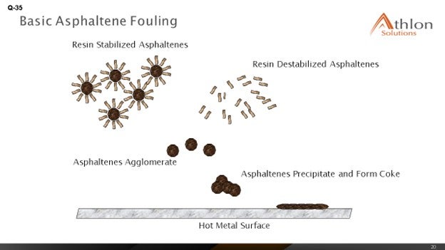
What we see is that the asphaltenes tend to be stabilized by resins and aromatics. When you get to high coking temperatures, those resins and aromatics start to crack and can form large-chain molecules that eventually reach the solubility limit; then, agglomeration and deposition starts to happen on the tube surface. The asphaltenes are also less stable in the absences of these resins and aromatics, and they start to deposit on the tube surface as well.
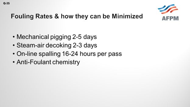
How do you minimize fouling and manage to remove some of the fouling that has occurred? There are various methods. Mechanical pigging can be done every two to five days. Steam-air decoking can be done at about the same duration: two to three days. Online spalling tends to be one of the favorites as it is being done 16 to 24 hours per pass. Then of course, well, being the chemical guy, anti-fouling chemistries have started to really show some differences in the ability to manage fouling and mitigate it.
THEISS (Marathon Petroleum Corporation)
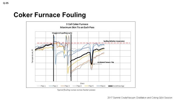
Kevin alluded to a lot of the mechanisms behind fouling. I am going to touch on a little of Marathon’s experience. We see big differences, obviously relative to crude slate. Kevin talked about that. At the refineries processing a lot of heavy Canadian, we can see fouling rates between 6°F and 12°F per day. We have seen double the fouling rates for those refineries processing heavy Canadian crudes. Really, tracking fouling performance is key to understanding not only when to go spall or pig or do whatever to decoke, but also to understanding how variable changes can affect fouling rates. So, if you want to mess around with the unit and see if it extends out your cycle, as far as the heater is concerned, understand that the data is really important.
The graph on the slide is an example of what we use at Marathon to track heater performance and determine when we need to spall our heaters. This specific example shows a staggered spall. It is a three-cell coker furnace, and the spalling cycle is somewhat staggered based on fouling rates on each individual cell.
I also want to touch on is some of the process variables you can alter to help affect coking. Obviously, we talked about crude selection. It could be very uneconomical to go down that path to select your crude based on your heater fouling rates, but it is an option. You just have to look at the big picture to be sure that is the right decision to make.
Thermal cracking can be minimized by increasing velocity and decreasing heat flux and outlet temperature. There are some penalties with decreasing outlet temperature as you will lose some yield. Obviously, it could also lead to some foaming events in the drums. If you have the equipment such as feed preheat, you will want to do your best to maximize feed preheat to minimize heat flux in your heater, which will help reduce some fouling. We have also done some testing with velocity steam and determined that going up to about 1.5% of velocity steam is really the peak amount of benefit you will get from increases in velocity steam. Too high velocity steam can increase your back pressure and actually reduce your heater tube velocity.
TARIQ MALIK (CITGO Petroleum Corporation)
Jeremy, you said that you had a heater with a fouling rate of 6 to 12°F per day. That is very aggressive. To what have you attributed that? You mentioned Canadian crude, but you cannot profitably operate a coker with a 12°F-a-day fouling rate. That means in about 21 days, you are done with the run-length.
THEISS (Marathon Petroleum Corporation)
Now we are doing it. It is not ideal, but primarily crude slate driven. It is a refinery that runs a lot of heavy Canadian crudes.
TARIQ MALIK (CITGO Petroleum Corporation)
Is that a double-fired or a single-fired heater?
THEISS (Marathon Petroleum Corporation)
Double.
TARIQ MALIK (CITGO Petroleum Corporation)
Double-fired heater and 12°F per day. That is not in the ballpark. What excess oxygen are you running on this?
THEISS (Marathon Petroleum Corporation)
I would say probably bouncing somewhere around 5 to 7%.
TARIQ MALIK (CITGO Petroleum Corporation)
That is good. Is it balanced or natural draft?
THEISS (Marathon Petroleum Corporation)
It is balanced.
TARIQ MALIK (CITGO Petroleum Corporation)
Okay. It is not adding up but thank you.
KOUSHIK GUMASTE (Baker Hughes Incorporated)
There is not a lot of literature available on the specific effect of sodium. Do you guys have any definitive proof that sodium does destabilize and cause more fouling? I have only heard it by word of mouth.
THEISS (Marathon Petroleum Corporation)
Actually, we recently had a little experience with testing caustic additions in our crude unit and determining the effects of translating that result to sodium fouling in the coker. With our testing that we did, it was really hard to tell the difference in coker fouling when we varied the level of caustic injection in the crude unit. That being said, there could have been other variables going on at that time. The bottom line is that we did not see a significant step-change in furnace fouling when we did some of those trials.
GAMBOA-ARIZPE (CITGO Refining & Chemicals, L.P.)
Just a secondary comment about the sodium: As Jeremy described, one of the other coker-related concerns with sodium addition, usually added upstream in the crude unit at the desalters, is the potential for the caustic embrittlement of the coker heater tubes, depending on your alloy. It is a problem that should not be ignored. The same embrittlement risk exists for the drums. The sodium starts leaching into the metal at a temperature as low as 800°F. Most of the delayed coking process occurs above that temperature, and so embrittlement risk is a concern that should not be ignored with sodium.
TARIQ MALIK (CITGO Petroleum Corporation)
Sodium is a well-known coke precursor, so coker feed should typically be less than 10 ppm (parts per million) sodium going in. If you have 20 to 25 ppm, you will impact run-length on the coker. Sodium is not good news in coker feed.
ALLEN KAISER (Delek Refining Ltd.)
I want to tell you two stories. First, we were blending a tank of caustic for our crude unit for injection downstream of the desalter. Due to some misalignments, we pumped straight 50 Baumé caustic into the desalted crude stream. When that hit the coker, we gained 100°F on the radiant TIs (temperature indicators) in a matter of about 12 hours. So, sodium, yes, has a big impact on TMTs (tube metal temperatures). As a result, we began paying attention to sodium a little closer; and then, we started – stepwise – bringing down the amount of caustic we were injecting into the crude unit.
Secondly, when we started measuring sodium, it was in the 50-ppm range. There was a big difference in fouling rate. The fouling rate was about three times higher than it had been in previous cycles. So, as we lowered that injection rate and got the sodium under 20 to 15 ppm, like Tariq was saying, yes, fouling rates started coming back down. Now, we are back to our more typical 0.5°F-a-day range. We got it back down in a more typical range.
HAROLD EGGERT (Athlon Solutions)
I think part of the confusion, if you are doing data analysis on sodium in the feedstock, is because no one has really delineated between sodium as sodium chloride and sodium as a function of overfeeding caustic. I think there is some debate as to whether it is the sodium or the sodium hydroxide. Most of the issues around the caustic are anecdotal. Like Allen said, we know we overfed caustic and that created an increase. But just looking at the lab analysis of the sodium in the coker charge may mislead you; the convention being that sodium chloride is not as detrimental to furnace fouling as overfeed of sodium hydroxide.
WARREN LETSZCH (TechnipFMC)
I have a question for the panel. If you are building a new coker today, how will you design the unit to do the decoking? Would you do steam/air decoking? Would you do it with pigs? What would you put in for a brand-new unit?
LÉGARÉ (Andeavor Martinez Refinery)
I will respond since I have one of the newest cokers out there. They are all designed for online spalling.
LÉGARÉ (Andeavor Martinez Refinery)
Oh, Yes. Definitely.
ROBERTSON (AFPM)
And that is the next question.
GAMBOA-ARIZPE (CITGO Refining & Chemicals, L.P.)
Yes, we will address that topic in the next question. We would not let you down, Warren.
KEVIN SOLOMON (Athlon Solutions)
The major factors affecting coker furnace fouling fall onto three key areas: mechanical, operations, and feed.
Mechanical: Configuration and design elements of the furnace that have significant impact to fouling are:
-
Tube diameter, which affects residence time and pressure drop.
-
Burner type, which affects flame impingement and issues arising from dirty fuel gas; and,
-
Tube metallurgy and surface roughness: 9 Cr, 12 Cr, 316 to 317L. Different metallurgy have different max skin temperatures. Some can be 150°F higher, which allows for longer run lengths between coking.
Operational: Deviation from industry published operating parameters can cause or exacerbate fouling. The following guidelines should be followed:
-
Maintain flow rate (cold liquid): 6 to 8 fps, which is the hydrocarbon flow rate before adding steam.
-
Bulk fluid rate: 10 to 12 fps; includes oil and steam.
-
Operating temperatures: less than 750°F.
Feed: There are several specific issues related to the feed material that affect fouling. Factors found in the coker furnace feed that can cause or exacerbate fouling are:
-
Sodium levels in the crude.
-
Heptane insoluble-to-carbon residue ratio.
-
Asphaltenes content in the crude.
-
Understanding of the metals type and concentration.
-
Understanding the stability of asphaltene, with respect to the crude slate, can help predict fouling and permit actions to be taken to reduce fouling rates.
-
Inorganic solids, such as corrosion by products, filterable solids and salts, and sodium can come from a variety of sources.
-
Corrosion byproducts can originate from upstream operations such oil production, transportation, crude oil storage, slop products, and contamination in the velocity steam or boiler feed water.
-
Salts can be from the salt water in the oil producing formation and brine contamination occurring during transportation.
-
Caustic may result from injection into the crude to reduce overhead chlorides.
-
Clay, dirt, and catalyst fines may be introduced from upstream production activities, transportation, and refinery processes upstream of the coker furnace.
We have already discussed that asphaltene destabilization – and thus, precipitation – is a leading cause of fouling. Destabilization can occur because of several factors, such as changes in press, temperature (greater than 750°F), and acidity. Free-radical polymerization is the process by which we believe fouling occurs. During this process, aromatics and resins are cracked. The asphaltenes react to form longer chains; and once solubility is exceeded, deposition and agglomeration occurs on the surface of the tubes.
Fouling rates vary depending on the crude slate, feed rate, feed properties, operating conditions, and the condition of the coker furnace. However, there are several ways we can minimize the impacts of fouling. Some are physical, and others are crude management and chemical treatment.
Mechanical pigging steam-air decoking and online spalling are activities that can help remove fouling buildup, to a certain extent. During any of these operations, feed throughput is reduced.
Crude management is focused on understand asphaltene stability and ensuring that the crude slate is as compatible as possible to prevent issues. Analyzing crude slate and determining asphaltene stability can give us an indication of potential fouling issues.
Utilizing a proven coker furnace antifoulant injected ahead of the furnace can help to reduce the rate of fouling without the need to reduce feed rate.
JEREMY THEISS (Marathon Petroleum Corporation)
Causes of Coker Furnace Fouling
Quality of feed is the major parameter in coker furnace fouling. MPC coker heater fouling rates have increased significantly over the past ten years, especially on coker units that process heavy Canadian crudes. We attribute the fouling increase to higher volume percentages of asphaltenes associated with the heavier crude slate. Heavy Canadian crudes can contain solids from the mining operations and diluent used to process these crudes, both of which can destabilize the asphaltenes and result in high heater fouling rates.
Other contaminants such as inorganics can also increase coker furnace fouling. Inorganics tend to precipitate in the convection section, where it is difficult to remove with online spalls. Inorganics, such as sodium, are introduced with incoming crude or injected during crude processing to manage overhead corrosion. It is recommended to manage sodium content below 20 ppm in coker feed.
Finally, the classic fouling mechanism for a coker furnace is thermal cracking. Coke from thermal cracking normally accumulates in the lower radiant section of the heater. Typical heater coking rate due to thermal cracking is around 1 to 4ºF/day depending on the asphaltene level in the feed.
Fouling Rates
One of our coker’s heater fouling rates more than doubled in the past five years with an increase in heavy Canadian crude throughput. This specific heater used to conduct decoking every six months and now goes through decoking every two months. Most refineries in the mid-west that process heavy Canadian crudes experience heater fouling rates between 6 to 12ºF/day. Our mid-west refineries that have similarly designed coker heaters to our gulf coast refineries can experience double the fouling rates.
Within MPC, coker heaters that spall online evaluate a shutdown every two to three years to pig the heater and hydro-blast the transfer line. We normally see heavy accumulation in the convection section and transfer line during the cleaning. Fouling of the transfer line increases back pressure which suppresses vaporization and increases residence time in the furnace. After three years, we have seen a 50-psi increase in furnace inlet pressure due to transfer line fouling. We normally see run-length increase by as much as 50% after cleaning the transfer line/convection section.
Reducing Fouling Rates
If a crude selection change is not an option or economical, there are some changes that could directionally assist with heater fouling. Thermal cracking can be minimized by increasing velocity, decreasing heat flux, and decreasing coil outlet temperature. Heat flux is a function of heater design, heater charge rate, and heater inlet and outlet temperatures. Assuming that the heater is properly designed, and the burners are evenly distributed, the operator can reduce heat flux by maximizing feed preheat and optimizing heater outlet temperature. We normally set heater outlet temperature to target coke volatile carbon matter (VCM) around 10 wt% (weight percent) and meet coke hardness specifications. Although, managing heater fouling by lowering heater outlet temperature can result in more hot drums and foaming events. We normally set an upper limit of 12 wt% on VCM to prevent drum operational issues. Running lower heater outlet temperature will result in a yield penalty, which must be considered.
We have completed several tests on the effects of velocity steam. These tests show an increase in velocity steam rate helps to a point but does not provide much gain in heater run length when velocity steam is above 1.5 wt% of the feed. We think higher velocity steam rates can increase back pressure to the furnace, which in effect reduces the velocity in the furnace.
CHRIS CLAESEN (NALCO Champion)
The furnace firing and design has a big impact and needs to be studied and understood before other parameters are investigated. Feed properties, such as solids and metals content and stability, will impact the coking rates and can be controlled by proper blending and removal of solids/metals at the desalter. Antifoulants can further help reduce the coking rates due asphaltene instability.
GREG SAVAGE (NALCO Champion)
The coker furnaces are often a limiting factor to unit and refinery throughput. One factor limiting charge to the furnaces is spalling, steam-air decoking, or pigging, which is triggered when any tube in a pass reaches the maximum tube metal temperature (TMT) for the given metallurgy. The increase in TMT can range from 0.1 to upward of 10°F per day, depending on the fouling rate and furnace operation. Primary causes of coker furnace fouling are poor tube cleaning, overfired tubes, local high heat fluxes due to fuel or burner issues, inadequate mass velocity, high heat flux, and high fluid bulk temperature, as well as high levels of metals and solids in the bulk fluid. Poorly cleaned tubes can leave deposits and rough surfaces, which can serve as sites for fouling initiation during operation. Burner tip plugging due to solids and liquids in the fuel can cause poor distribution between the ports or port enlargement (as a result of erosion or oxidation), which can lead to high burner tip pressure, flame impingement, too few burners, uneven heat release, and fireside tube fouling from products of incomplete combustion and ash. These burner tip issues can cause localized hot spots that can promote the formation of coke deposits. Inadequate mass velocity leads to increased residence time and film temperature, as well as reduced turbulence. In low velocity regions, asphaltenes are more readily removed from the bulk fluid and are more likely to form coke. Low fluid velocity is a major contributor to furnace tube coking. High heat flux due to overfiring can be caused by poorly tuned instruments, fuel composition change, excessive throughput, high exit temperatures, or poor operational control. High heat flux raises the fluid film temperature and increases the coking reaction rate. High exit temperatures increase the fluid bulk temperature and therefore increase the potential for coke formation and deposition. Salts, dirt, caustic, and other contaminants in the fluid can catalyze asphaltene formation, increase coking tendency, and adhere to deposits.
Tube-side fouling deposits are typically a combination of corrosion and fluid decomposition products, as well as salts or dirt. These solids can adhere to the tube walls forming deposits, which interfere with the heat transfer and increase localized temperatures. These products are formed from a complex reaction dependent on the temperature of the wall film and the time of exposure to that temperature, i.e., wall film thickness (related to fluid velocity). Consequently, the heat flux and the mass velocity heavily influence the rate of fouling. Coking reduces potential unit run lengths because it increases heater tube temperatures to near metallurgical limits and also increases pressure drop in the heater, causing hydraulic limitations. Reducing the frequency of coking incidents and the rate of coke formation is thus important to increasing plant utilization.
Coker heater fouling is promoted by thermal destabilization and precipitation of asphaltenes followed by dehydrogenation of the deposited species at the furnace tube temperatures to form coke. Asphaltenes are kept suspended in the feed through resins that are attached to the particles. As the feed is heated, the resins increase in solubility and detach from the asphaltene particles, which causes the asphaltenes to precipitate. The asphaltene particles then lay down on hot surfaces and form coke deposits. The formation of asphaltene precipitate and degradation to coke can be catalyzed by iron, sodium, and vanadium. Tube wall roughness from corrosion, fabrication, poor mechanical cleaning, or deposition of asphaltene particles can act as a coking initiator.
The furnace exit temperature controls the flow of fuel and the distribution of feed to the passes and can be adjusted to increase cracking and improve yields. Consequently, proper control of the exit temperature and instrument tuning is important to optimizing unit profitability while minimizing the fouling risk. Burner tips that are frequently taken out of service increase the risk for formation of localized coke deposits. During spalls, burners can be taken offline to reduce the heat flux. Removing burners rather than controlling the fuel gas flow during a spall can lead to localized hot spots and formation of coke deposits.
Hot air can increase combustion efficiency, but it has also warped air distribution equipment at some refineries, which has caused some uneven heat flux distribution, and contributed to fouling. Some refiners lack sufficient O2 sensors in the firebox in each pass. At least three O2 sensors are recommended to ensure proper combustion and distribution. Excess O2 is controlled, depending on coker margins, and some refiners have found that higher excess O2 reduced spall rates. Additionally, CO meters can indicate incomplete combustion and the need for additional O2. Air and fuel gas distribution issues can result in the firebox ends being consistently colder than at the center, which increases the risk for the formation of localized coke deposits. Also, sagging in tubes – due to loss of mechanical support – can change flows and heat distribution, leading to hot spot development.
Cleaning of the furnace convection section can be done with dry ice. However, limited mobility and access can restrict the amount of surface that can be reached. Despite the limitations, recoveries of over 100°F have been found by refiners. External fouling of the convection section results in elevated heat flux in the radiant section, which increases the formation of coke deposits. Poorly cleaned tube internals can leave deposits and rough surfaces, which can serve as sites for fouling initiation during operation. After cleaning a tube, the temperature should consistently recover; otherwise, the cleaning may not have been effective.
The total heat flux is calculated using the fuel gas rate, fuel energy content, and tube surface area. Usually, the heat flux in the radiant section is 70 to 80% of the total heat flux and should be compared to the design maximum. Mass velocity is calculated using the cross-sectional area of the tubes, the mass flow rate, and the steam injection rate. Generally, the recommended mass velocity is between 350 to 450 lb/ft2-sec (pound per square foot per second). Steam is often injected for safety reasons, to change partial pressures, and to increase the velocity through the heater. A general guideline for steam injection is 2% by weight.
Coker heater tube fouling rate can be controlled through firing rate, velocity steam, and specialty chemicals. The most effective method of controlling heater tube fouling is increasing mass velocity, followed by reducing heat flux. Blending of slurry oil, increased recycle, or even light coker gasoil into the feed have each been effective at reducing furnace fouling rates, but generally with economic penalties. Laboratory simulation of blending these components into the coker feed can indicate the estimated benefit for a full economic evaluation of these options.
When process parameters are within the recommended envelope and other blend streams are not economical, proper injection of chemicals can help reduce the fouling rate. The coker heater protection program implemented by NALCO Champion uses a combination of passivation, dispersion, and coke suppressant chemistries to reduce the fouling rate. A phosphate-based filmer passivates metal surfaces, reducing activity, thereby inhibiting the metal surface’s ability to catalyze the formation of coke from asphaltene particles. An asphaltene dispersant stabilizes the resins that keep the asphaltene particles dispersed and therefore reduces the potential for deposition. Inorganic dispersant chemistry reacts with reactive sites carried in the coker feed, which initiate the formation of coke deposits.