Question 27: What methods do you use to reduce particulate loading on or debottleneck of existing filtration equipment in a HPU unit without reducing catalyst cycle life?
DAN MORTON (Haldor Topsoe, Inc.)
The use of feed filters is highly recommended, but it is important to choose a filter size that will be manageable; meaning that if a 5-micron filter is used, it will most likely have to be replaced or backflushed several times per day, which is not practical. However, if a too-large filter size is used, it will not be effective. The only way to reduce the particulate loading on a feed filter is to increase the filter size, thus allowing more material to slip through. In order to notimpact the catalyst life cycle, it will be necessary to install a scale catcher in the reactor to catch the extra material that is now going to the reactor. The scale catcher is located on top of the inlet distribution tray (i.e., above the tangent line) and will not reduce the catalyst volume in the reactor.
The scale catching tray will collect the fines, scales, etc. in order to avoid plugging of the distributor tray and the catalyst bed below. Haldor Topsoe has developed very effective scale catchers for both gas-phase and liquid-phase hydroprocessing units.
Single-Phase (Gas) Flow
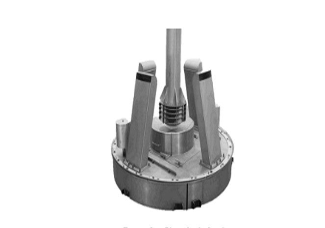
The gas-phase scale catcher removes particles from the gas. The equipment is designed specifically for the type of particles typically seen in a naphtha feedstock.
Two-Phase (Liquid and Gas) Flow
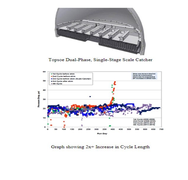
There are two primary designs by Topsoe for scale catching in two-phase flow: a single-stage filtration tray for larger particles and a dual stage filtration tray, called the HELPsc™ (High Efficiency Low Pressure) scale catcher.
The single-stage scale catcher is made to simply allow the larger particles (greater than 100 microns) time to slow down and settle out of the liquid flow and then precipitate out onto bottom of the scale catcher. They canthen accumulate and be easily cleaned/vacuumed out at the next turnaround. These heavy particles never reach the bed below and plug the catalyst.
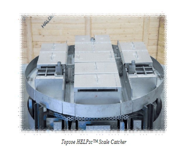
Haldor Topsoe HELPsc™ Technology
Haldor Topsoe’s second generation High Efficiency Liquid Phase scale catcher (HELPsc™) is a two-phase, dual-stage catalyst basket scale catcher which provides improved retention of both the large and much smaller particles in the range of 10 to 20 microns, resulting in further improvements in cycle length. The technology provides a dual-stage system for improved scale-catching efficiency, providing combined sedimentation and filtration stages.
Dual Filter Principle for Liquid Flow:
1.Liquid accumulates on the tray.
2.As soon as it reaches the right height, it flows into the filter catalyst cassettes.
3.The liquid is pushed through the first (and the second) filtering unit until the pressure drop across the filter causes the liquid height to grow over the filter.
4.When the liquid height exceeds the height of the first filtering chamber, the liquid bypasses the first filter, collects in the space between the two filters, and is pushed through the second filter.
5.Eventual bypass of the dual filter system occurs when it reaches capacity.
6.No pressure drop is accumulated over the entire life cycle of scale catcher tray. The two-filter chambers are filled with a specialty catalyst in two different sizes to further improve the filtration efficiency. For additional information, please contact your Haldor Topsoe representative.
SANDER VAN SCHALKWIJK (Shell Global Solutions)
We can distinguish two scenarios. First, fouling material is coming from the upstream unit or from storage tanks. In this case, a feed filter (cartridge type or backwash type) installed on the feed line can solve the fouling issues by capturing the fouling material coming from the upstream unit. Another option is also to install a “deep bed” filter on the feed line, which is basically a small guard bed reactor full of grading material. Feed filters have a higher capex (capital expense) than the deep bed filter, but no opex (operating expense). The grading in the deep bed filters must be changed once it is plugged leading to higher operative expenses and requiring more maintenance.
Second, fouling material is produced within the unit. In this case, in order to capture the fouling material produced within the unit and upstream the reactor, grading can be loaded on top of the catalyst bed and/or a scale catching tray/filter tray can be installed above at the top of the reactor. Cycle length can be significantly increased by optimizing/loading grading layers on top of the catalyst bed and by also by installing a scale catching tray or filter tray. Filter trays are the best filtration technology we can install in the reactor itself as they capture both big and small sized particles (unlike the scale catching tray which captures big particles only). Of course, a combination of all these solutions can be considered.