Question 21: What programs or systems do you employ to monitor hydrotreater furnaces and prevent tube failures and loss of containment? Can you share your experiences using technologies to implement online temperature monitoring of tube skin temperatures?
JEFFREY MUELLER (Marathon Petroleum Company)
In nearly all hydroprocessing heaters, MPC has installed tubeskin thermocouples in order to provide continuous monitoring of tube metal temperatures to the DCS (distributed control system) operator. These thermocouples are strategically located in the heater at the areas with the highest estimated maximum heat flux. For most heaters that operate at lower firebox temperatures, the welded-on type of thermocouple has been fairly reliable for the turnaround cycle. In this installation, the thermocouple is designed to wrap around the tube, with the end welded to the hot side of tube. The wiring to the transmitter is ran on the back side of the tube and typically out the heater can, where the transmitter is located. MPC has experienced much lower reliability with the retractable thermocouples (not welded directly to the tube).
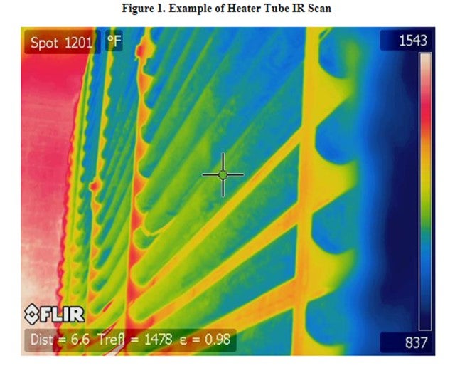
While tubeskin thermocouples provide continuous monitoring, it is important to remember that they are representative of only one point in the heater. On a periodic basis, which varies based on heater service and history, MPC inspection will take an IR camera shot of the heater tubes to look for any localized hot spots (see Figure 1).
NHT Heaters
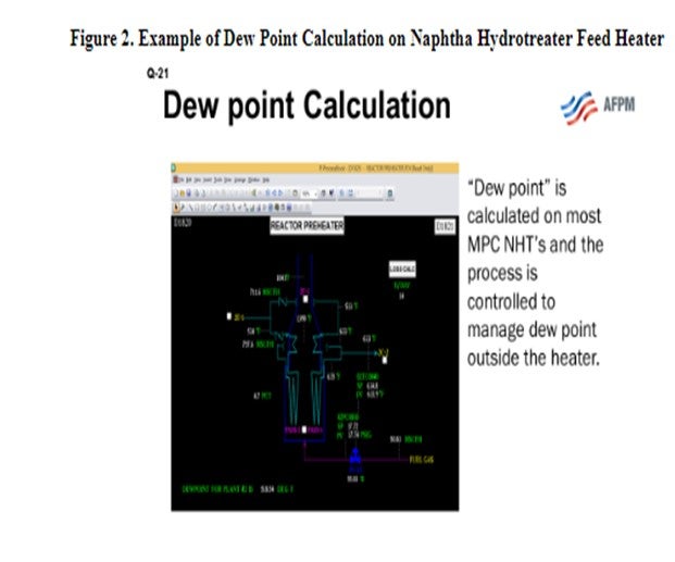
On certain services, MPC has implemented additional practices to minimize heater fouling. One specific example is naphtha hydrotreater (NHT) charge heaters. On most NHT units, the heater is designed to be 100% vapor-phase entering the heater. Fouling occurs at the point in the process where liquid completely vaporizes, particularly when the unit processes oxygen-contaminated feeds. As the feed/effluent exchangers foul, this point (a.k.a., dew point) is pushed further and further downstream in the process. If allowed to enter the heater, the fouling may occur in the heater (usually convection section) and cause localized coking that could possibly go undetected. In these situations, MPC will use lab data and process conditions to calculate a dew point and limit the process to maintain dew point before entering the heater.
On some NHT units, the feed is designed to vaporize within the heater. In these situations, the heaters may be equipped with skin temperatures to measure the section of the heater tubes where vaporization is expected to occur. In addition, the heater may have extra design precautions, such as upgraded tube metallurgy and individual pass flow indication and may also be pigged on a frequent cycle to remove any deposits.
SCOTT SEXTON (Haldor Topsoe, Inc.)
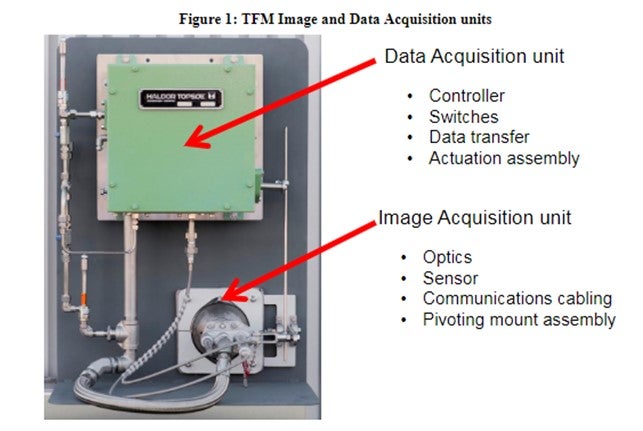
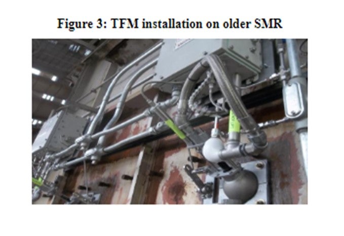
Haldor Topsoe’s technology for monitoring furnaces, including tube temperatures, is Topsoe Furnace Manager (TFM). TFM is a system of multiple image acquisition and data acquisition units installed permanently on a fire box to monitor burner flame intensity, tubeskin temperatures, and firebox component mechanical integrity continuously, 24/7. TFM captures images of the fire box within each unit field of view every second, and stores those images in a historian, for future reference. TFM provides alarms for temperatures outside of the designated operating envelope, with continuous displays in the control room, as well as remotely, with computer networks. Immediate operational issues are known on the control room displays, and longer-term planning is facilitated with images archived in the Historian to enhance overall effectiveness and operational excellence for the entire furnace support organization.
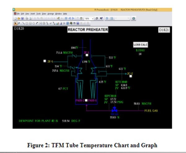
TFM is commercialized on three continents at multiple locations. Reliability of the system overall is equivalent to the plant utilities supply (instrument air and power) and is enhanced by the inherent design encompassing multiple image and data acquisition units on the same fire box. Tube temperatures and burner intensity are graphed and charted similar to process control parameters.

Human interaction with the fire box is greatly reduced due to the remote accessibility of TFM data and the continuous display of images in the control room. TFM data is captured and archived automatically so that data transfer handoffs are minimized. TFM is built for industry with Class1 Division2 components and made for harsh industrial furnace applications. All systems are installed with maintain ability and safety in mind so that furnace operations can be managed with more productive use of personnel time and energy. Data analysis and evaluation is facilitated over current practices involving firebox data acquisition by personnel.
PAT BERNHAGEN (Amec Foster Wheeler)
Tubeskin thermocouples (TSTCs) are a primary way of monitoring the tube metal temperature on a regular basis. Other methods, such an optical pyrometry and thermal imaging, are useful on a periodic basis, although both have limitations. The TSTC can only monitor a specific spot in the heater, and its readings can be impacted by the burner flames if not properly shielded. Pyrometer and thermal imaging readings are impacted by background effects and scale/fouling on the tube OD (outer diameter). A combination of these methods is useful: Use the imaging tool to locate the hot spots in the heater; and later, properly install TSTC at that location. Thermal readings can then be indexed to that spot (assuming the TSTC is more accurate) for full coil monitoring. Proper installation of the TSTC is the most important part of the monitoring process. It is best to follow the manufacture’s guidelines on installation and expansion loops or perhaps have them supplied and installed by the manufacturer.