
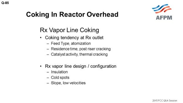
Question 85: What operating practices or technology upgrades are you using to manage coking in the reactor overhead line at the main fractionator inlet?
SINGH (Indian Oil Corporation Limited)
Feedstock, catalyst, and reactor hardware all play a very major role in the vapor line coking. Coking of the reactor overhead line is a major concern, particularly when we are processing resids. Catalyst formulations designed for higher hydrogen transfer reactions, coupled with high aromatic feed, tend to produce higher boiling point PNAs (polynuclear aromatics), which have a tendency to condense and form coke in the vapor line. Design and configuration of the vapor line is also a very important factor.
There are different reasons that are all extremely unit-specific for vapor line coking, and they can predominantly be classified into two categories. Number one is factors leading to the presence of components which tend to produce coke at the reactor outlet. These factors include heavier feeds, aromatic feeds, improper atomization, post-riser cracking, high residence time in the reactor, low activity of the catalyst, comparatively more thermal cracking, etc. The other factors are related to the configuration and design of the reactor vapor line which influences condensation and coking. The phenomena of vapor line coking get aggravated by cold spots in the reactor vapor line, improper insulation, damaged insulation, low velocities, improper slope, cool patches in the vapor line, etc.
We have experience operating both hot- and cold-walled vapor lines, as well as a variety experience has been that even with the old design of the feed injectors, the extent of vapor line coking was much less while processing VGO in comparison to processing resid feed with modern atomizers, thereby indicating the significance of the type of feed on vapor line coking. In one of the units, the configuration of the vapor line was such that it had too many cold spots. It had the worst slope, and we had the tremendous problem of coking in the vapor line, though the unit did have a modern feed injection system. After correcting the problems related to the vapor line, to a very large extent, the problem could be eliminated. Hence, type of feed and vapor line configuration are important factors regarding vapor line coking.
Some suggestions to avoid this problem: We need to start with the best feed vaporization. Avoid mixing slurry with the feed. While using slurry filters, it is recommended to use feed as the backwash medium rather than HCO to avoid having the once-cracked material going back to the riser. Avoid cold spots in the vapor line and based on the design, insulate the vapor line well. During insulation, special attention should be paid to supports, manways, fittings, and flanges. Avoid cooling the vapor line with cool purge streams. In one of our units, we had to provide some steam purges in the vapor line that significantly enhanced coking within the line. Some old designs might have some purges or bypasses going in the vapor line which, again, should be avoided.
REYNOLDS (Phillips 66)
I will just reemphasize one point. Yes, you want to make sure you minimize all of the heat sinks on the overhead line. I recommend you do regular infrared scans or thermography and look for hotspots. Do that annually, quarterly, or some other frequency, which is especially important after a turnaround. Make sure you get a good quality baseline infrared scan, so you have a baseline of where you started. I think the dew point in the overhead vapor lines is also 600 to 700°F or so. You want to make sure you stay well above that temperature.
ZIAD JAWAD (Technip Stone & Webster, Process Technology)
Obviously, there are a lot of technology options available to help you minimize coking. It is really difficult to measure pressure drops across the vapor line. Typically, you are limited to instrumentation measuring single pressures, and you then have to subtract those pressure measurements. Obviously, you can take pressure at the top of the plenum; and on the main fractionator, you may not have a spot. So, you might want to think about having some dedicated tubing, if it is not short, to have an actual DP (differential pressure) at the top of the level bridle to get a downstream pressure.
W. LEE WELLS (LyondellBasell Industries)
The actual question stated that the main fractionator inlet was the concern. I did not write the question, but we have a similar concern. It is not on the line itself; it is only right where it goes into the fractionator in the dead spot. The line comes in from the side and elbows into the main fractionator. On the inside of that sweep, there is a dead spot that tends to build up coke, which breaks off and fills up the bottom of the main fractionator. Does anyone have an answer as to why that occurs? Also, has anyone else seen coke buildup in the same location? Obviously, someone else submitted this question.
WARREN LETZSCH (Technip USA)
Yes, we have done that. [Laughter] It is not uncommon to get a donut around the inlet to your main fractionator. In our old units, I have seen areas where we have built up a five-pound pressure drop across the donut. I think it has a lot to do with the velocity going into the main fractionator – whether it is too low or too high or if it is sloped properly – and the insulation around it. Frankly, that has been addressed in the old NPRA/AFPM transcripts.
I will just tell you about one even more interesting situation. You know, when you guys get your FCC units, you go to the licensor. He gives you a process design package, and then you go to the detailed engineering company. You think the detailed engineering company personnel are experienced and know what they are doing. Here is your reactor coming out with the main overhead vapor line, and you thought you would go into the main fractionator. Oh, no! This guy was really clever. He came out down and put it in the pipe rack. It went around and then came all the way around to the back of the fractionator, and you ended up with about a 300-foot vapor line. He was complaining about coke in it. [Laughter] Actually, it was quite a good condenser, particularly if you put it into a place with a tropical climate and where you can get two inches of rain in an hour or so. It is a terrific condenser. These situations really do happen.
RICHARD RUSSEFF (CVR Refining, LP)
I have seen a similar phenomenon right at the blind flange location on the tower where the coke tends to build up and then streak into the tower building, creating a good pressure drop. We had that same issue, which we ended up solving with a combination of steam rings and insulation to try and eliminate that spot during normal operations. However, it was quite a bit to chisel out. It was very odd shaped because it had started at the flange and then worked its way into the tower, making horizontal stalactites on its way into the tower. Is that the same situation you saw?
W. LEE WELLS (LyondellBasell Industries)
We do not have a flange in that location, and we do not see stalactites.
ROBERT (BOB) LUDOLPH [Shell Global Solutions (U.S.), Inc.]
We have seen a variety of coke formations pinching the main fractionator inlet, creating pressure drop between the top of the reactor and the top of the main fractionator. Shell did a review of what might contribute to the coke growth and concluded that the velocity was a player. However, the ranking of the process parameters suspected as coke growth contributors is quite site-specific. We have conducted CFD analysis to better understand what might be occurring, but we are not satisfied with the results. Suspected locations and causes of pressure drop increases are, many times, unconfirmed when the equipment is entered during turnaround. Remediation and prevention of main fractionator inlet coking remains a big area of learning for us.
SANJIV SINGH [Indian Oil Corp Ltd. (IOCL)]
Feedstock, catalyst, and reactor hardware all play major roles in vapor line coking. Coking of the reactor overhead line is of most concern when processing residues. Catalyst formulations designed for high hydrogen transfer reactions, coupled with heavy aromatic feedstocks, tend to produce higher boiling point PNAs, which have a tendency to condense and form coke in the reactor vapor line. Design and configuration of the vapor line also plays a very major role in its coking.
Though the problem of vapor line coking is unit-specific, there are two major factors contributing towards reactor vapor line coking:
-
Presence of components having higher tendency to coke at reactor outlet: Heavier feeds, aromatic feeds, improper atomization, post-riser cracking, high residence time in the reactor, low activity of the catalyst, and comparatively higher thermal cracking are the major contributing factors to enhance vapor line coking.
-
Configuration and design of reactor vapor line influencing condensation/coking: Cold spots along the vapor line (caused by improper/damaged insulation, exposed fittings, etc.), low velocities, improper slope, and cold purges in the vapor line enhance vapor line coking. Sometimes high vapor velocity in the vapor line near the main column inlet results in column bottom material getting sucked into the vapor line, leading to coking at that location. Attention should also be paid to the design and operation of the main column bottom section to avoid coking in the vapor line at column inlet nozzle.
At Indian Oil, we have experience operating both hot and cold wall vapor lines, as well as very old designs (bayonet/shower head) for VGO and modern feed injectors for VGO/resid. As per our experience, the problem of vapor line coking was considerably less while processing VGO even with shower head feed injectors. In comparison, while processing resid, vapor line coking occurs even with modern feed injectors. The problem occurs even with a cold wall design. In one of the units, configuration of the vapor line was an area of concern with too many cold spots and reverse slope. Coking in this line was considerable requiring very close monitoring of pressure drop across the line. Correcting the shortcomings, along with improved atomization of feed and higher catalytic activity, almost eliminated the problem.
Some suggestions to minimize/avoid vapor line coking are:
-
Start with the best feed vaporization. Optimize the atomization across the feed nozzle, avoid mixing slurry or other cracked stuff in the feed, ensure recycled slurry atomization, reduce the feed with heavy tail in VGO crackers, and maintain minimum feed preheat temperature. In units equipped with slurry filtration, using raw oil as back-flush medium instead of HCO would avoid recycling of high aromatic cracked material back to the riser. Operating the unit at possible high MAT (microactivity test) is desirable.
-
Avoid cold spots in the vapor line. Based on the design, insulate the vapor line well with special attention to line supports, manways, fittings, flanges, etc. Avoid cooling the vapor line with cool purge streams, including steam. Eliminate low points in the line which may accumulate and condense heavies. Some older designs had recycled back to the vapor line. These should be avoided. Cold wall design of the vapor line is preferred.
NIKOLAS LARSEN [Marathon Petroleum Company (MPC)]
For previous MPC information, see Question 36 from 2009 AFPM Q&A. Reactor vapor line coking is typically caused by low severity operation or poor feed atomization. Long-chain paraffins that survive the cat/oil contact and reactor conditions are prone to condensing on the vapor line at low reactor temperature and lead to coking. MPC has not experienced any vapor line coking due to low reactor temperature operations. However, we have guidelines to maintain an ROT higher than 930°F for all units (except resid units).
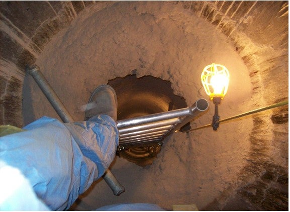
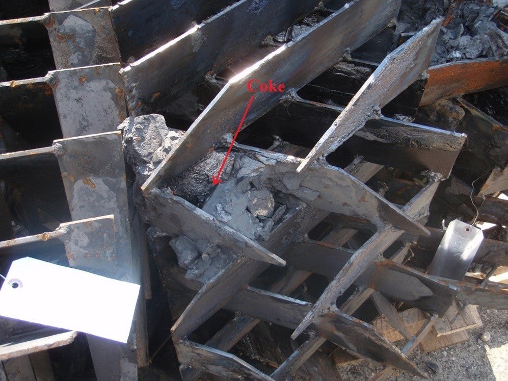
The only vapor line coking incident occurred because of condensation. A portion of a reactor vapor line was replaced during a scheduled unit turnaround. The transition between the hot wall and cold wall components was not properly insulated. This resulted in a cold spot where reactor vapors condensed and formed coke. The coke ring caused a 1.5 psi pressure drop. The problem was diagnosed from regular, single-gauge unit pressure surveys. A picture of the coke deposit is shown below.
Year
2015
Process
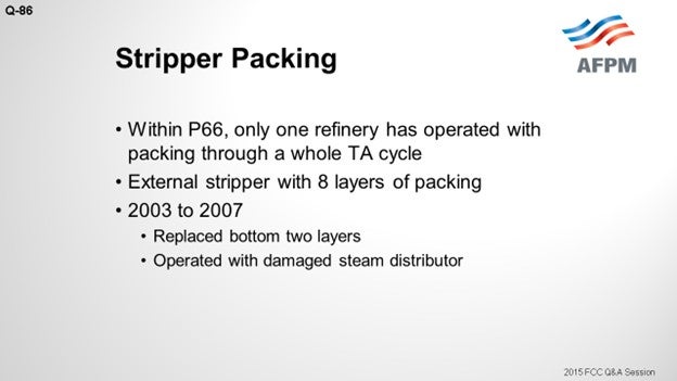
Question 86: With more refiners upgrading to packing in the reactor stripper, what has been your experience with reliability? When do you consider removing packing for inspection during turnaround? How much of the packing does one spare?
REYNOLDS (Phillips 66)
At Phillips 66, we have three refineries that have packed strippers. Two of those have not yet run through a full turnaround cycle, so I cannot really comment on their reliability yet. The first refinery to put in the grid packing within P66 did so in 2003. It has gone through two turnaround cycles since then. It has an external stripper and is fairly small in size. In each turnaround, we have pulled out all eight layers of the packing.
In the first run from 2003 to 2007, we ended up replacing the bottom two layers just due to general thinning. There was about a 60% metal loss. There was one caveat to this run: The steam distributor underneath the packing failed during the run; so, most of the time, we ran with poor steam distribution. The adjacent layers moving up from the bottom of the bed had 20 to 30% loss as well, but we deemed them okay and reused them.
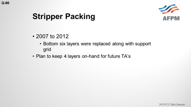
In the next run, from 2007 to 2012, we ended up replacing the bottom six layers. Some of that damage was on two of the layers that had not been replaced on the previous run. We could have reused the two top layers that were replaced; but since we already had them out of the vessel and had new packing sitting right there, we replaced the lower six of eight layers, as well as the support grid underneath the packing. It was knife-edged and had some thinning. Going forward, we plan to keep four layers on hand just for turnarounds.
I have included some pictures. The first one is from the first run in 2007. You can see that there are some knife edges and it is worn out. What I like about this picture is that it is from April. The white stuff is not a catalyst. This is snow. [Laughter] You can guess which part of the country this refinery is in.
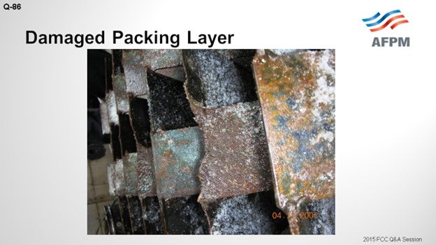
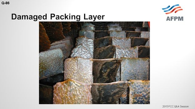
On the next slide, you can see another picture of that damage. There are erosion patterns in this wear. You can that see it is just worn down.
I will say that going into both of these turnarounds, there are no indications of any pour stripping. The stripper runs great. We do not have any plans to make modifications. P66 recommends that you keep the flux rate under 600 pounds per hour per square foot (pph/ft2) of cross-sectional area. We run about 1100 pph/ft2, so we are quite a bit above the guidelines.
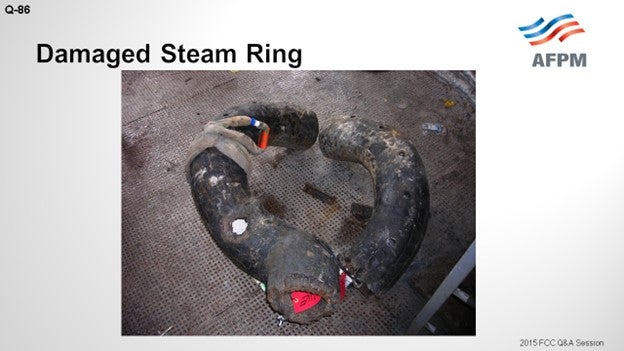
The last slide shows the steam ring. It was C-shaped. It failed in two locations. I believe there were bad welds, as dissimilar welds have failed. So, we put a pipe grid-type distributor in there, and it has done fine since then.
LARSEN [Marathon Petroleum Corporation (MPC)]
In Marathon, we only have one unit with the packed reactor stripper. This stripper was installed in 2010, so we have not been through a turnaround cycle on this unit yet. We have not seen any problems with stripping in it. We are not really planning to pull the packing out of this stripper. We are planning to inspect it from the top and from the bottom. The external IR surveys we do around the stripper do not indicate any refractory problems. So that is our plan.
RAMA RAO MARRI (CB&I Lummus Technology)
Mark, I just have one question for you. The layer is from the top of the first one. Which is the portion of the layer?
REYNOLDS (Phillips 66)
Just the lower one. The one that is damaged is at the bottom. The damage has been worst at the bottom and progressively better going up.
RAMA RAO MARRI (CB&I Lummus Technology)
So, there could be a situation where the starter packing could be damaged from the top also. If the catalyst level is not at the level at the top of the grid, then there could be some impingement of the catalyst coming at high velocity from the cyclone dipleg, which could also impinge and possibly damage the top. So, it is essential to keep the catalyst bed level such that all the grids are immersed in the bed and the packing catalyst is covered.
NIKOLAS LARSEN [Marathon Petroleum Company (MPC)]
MPC only has one FCC with a packed reactor stripper. This unit is in its first cycle following installation; and so far, reliability has been good. We are not planning to remove packing for inspection; we will inspect from the top and bottom. External IR surveys have not indicated any internal refractory problems.
JOSH TREISNER (Monroe Energy, LLC)
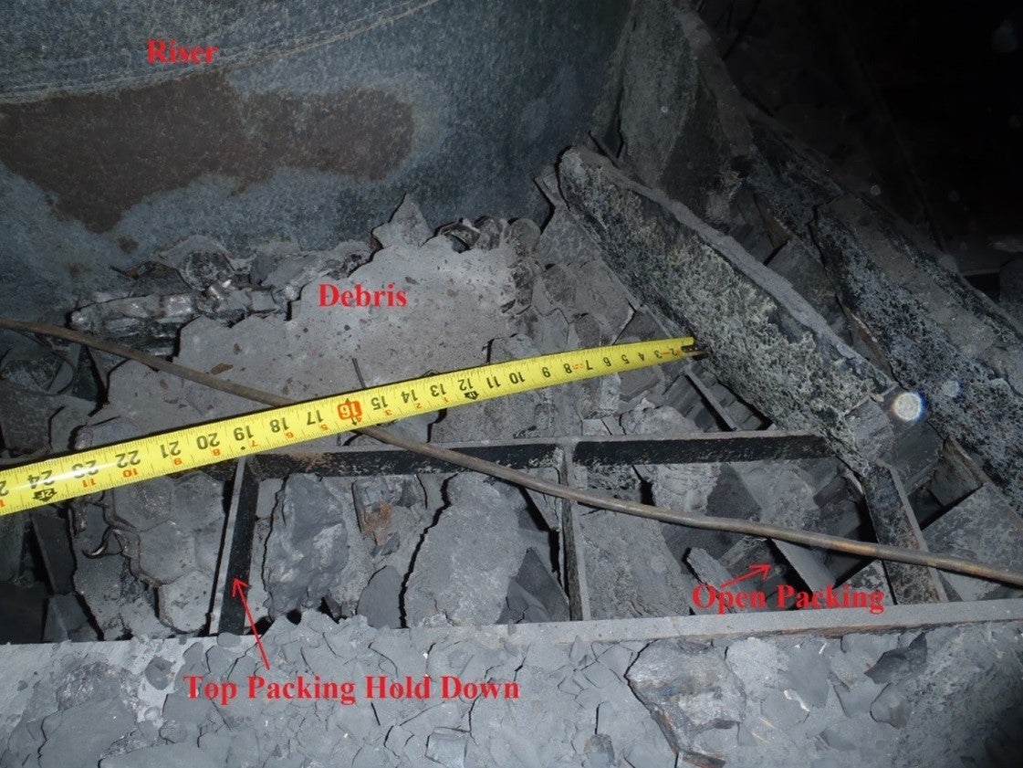
We installed packing in our reactor stripper in 2006. So far, the only issue we have seen was in 2012. When we went into the reactor, we had refractory and coke debris from various areas of the reactor that had fallen onto the top of the packing and partially clogged and blocked a portion of the packing. We had already made the decision to remove all of the packing to evaluate whether there was any erosion with the new configuration (there was not), but we would have needed to remove at least the top two layers for cleaning anyway due to the debris.
Once removed, we did not see any noticeable erosion on the packing itself; but in anticipation of possible issues, we had ordered one layer of spare packing prior to the outage. I will caution that the price per layer was twice as high when just ordering one or two layers compared to ordering a complete replacement (eight layers for us) and lead time for even just one layer was in the range of 12 weeks. I would also caution that even though our packing was very robust, some sections still got deformed during handling, although not badly enough to need to be replaced. For our next outage (if we did not already need to remove the packing for another reason), we would have suggested having one layer on hand and simply inspecting from the top and bottom and determining whether cleaning or replacement was needed from there.
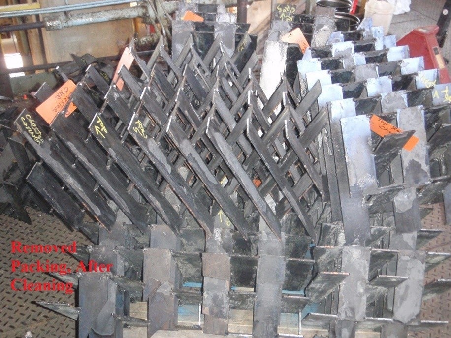
The following pictures are of the as-found condition and the packing, and some pictures of it once it had been removed and then cleaned.
Year
2015
Process
Question 87: What has been your experience with gas and/or catalyst bypassing behind monolithic refractory linings? What are the possible approaches to prevent or correct this issue?
SINGH (Indian Oil Corporation Limited)
Most refractory problems are often due to poor installation and cyclic service. Hot spots are observed in the shell due to major refractory failure; but much more commonly, from the circulation behind the refractory. We have experienced gas and catalyst going behind the monolithic refractory lining. In such cases, hot gases are driven through the refractory by the head of the catalyst just above the entry point. The gas then exits from the dilute phase at the lower pressure zone. As the gas continues to travel through cracks and heats up the metal, the metal tries to expand while the refractory does not expand, which leads to refractory failure.
Detection of localized refractory failures is done by thermography or visual inspection. Unit operation is commonly sustained by providing external cooling to the affected area, either by the low-pressure stream or air, depending on the case. And if the shell temperature cannot be maintained within the designed temperature, then we have to go for emergency shutdown and do the repairs.
The refractory failures can be minimized by proper refractory selection, anchorage, layout, and inspection after the dryout. We have changed external hot-wall risers to cold-wall risers in a couple of our units. The cold-wall systems can be monitored using thermography, which avoids surprises. As per our experience, in comparison to hot-wall design, the cold-wall riser in the orifice chamber does not require frequent refractory repairs. All of the monolithic refractory jobs are done under direct supervision of refractory experts.
As a standard practice for refractory repair, a fresh application of refractory is not done over partially fallen refractory. For repairs, the refractor must be removed up to the shell to expose the anchors before applying the refractory. In the case of refractory repair, if the repaired area is more than five square meters, then we will conduct refractory dryout by strictly following the specified procedure.
FOSHEE [Shell Global Solutions (U.S.)]
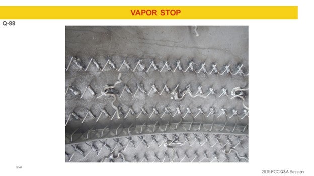
I will say that at Shell, we have definitely noticed bypassing behind monolithic refractories, especially in areas with extreme geometries such as in a Y-piece or a J-bend. Shell’s approach has been to use what is called a vapor stop. It is a ring of steel that basically protrudes into the refractory a certain distance and stops the bypassing.
SANJIV SINGH [Indian Oil Corp Ltd. (IOCL)]
Common failures of refractory linings are due to fracture, spalling, erosion, shear, separation from the shell, or increased thermal conduction. Most problems are often due to poor installation and/or cyclic service. Hot spots are observed in the shell due to major refractory failure or, much more commonly, hot flue gas circulation behind the refractory. We have experienced gas/catalyst bypassing behind monolithic refractory linings. In such cases, hot gases are driven through the refractory by the head of catalyst bed above the entry point. The gas then exits into the dilute phase/lower pressure zone. As the gas continues to travel through cracks and heat up the metal, the metal tries to grow or expand in an outward direction and attempts to pull the refractory lining with it. The refractory, on the other hand, will be resistant to any movement; hence, the nature of any cracks and gaps alters and change as the metal temperature changes. This fluctuation allows new gaps in the refractory to form and/or existing gaps to alter and is often viewed as a shift or movement in the hot spot location. In such situations, we normally try to maintain the shell temperature with air/steam injection until an opportunity to repair the affected area is available. If the shell temperatures cannot be maintained below design temperatures, then we shut down as soon as possible and make a repair.
Refractory failures can be minimized by proper refractory selection, anchorage layout, installation, and inspection after dryout. In addition, avoiding frequent and severe thermal shocks (startup and shutdown) also minimizes potential of failure.
We have changed external hot wall risers to cold wall risers in couple of our units. The cold wall system can be constantly monitored using thermography. This avoids surprises. As per our experience, in comparison to hot wall design, the cold walled riser and orifice chamber do not require frequent refractory repairs. All the monolithic refractory jobs are done under direct supervision of a refractory expert. As a standard practice for refractory repair, fresh application of refractory over partially fallen refractory is not done. For refractory repair, refractory removal up to the shell to expose the anchor is ensured before applying the refractory.
In the case of a refractory repair, if the repaired area is more than 5 m2, dryout is carried out prior to putting the refractory in service. For dryout, the recommended cycle is strictly followed. A typical dryout cycle includes heating to 110°C (230°F) to 120°C (248°F); holding for eight hours, depending on refractory thickness; and then, heating up to 350°C (662°F). For holding at 110°C (230°F), we find that MAB air is sufficiently hot enough to maintain the temperature.
To strengthen the monolithic refractory, we normally add stainless steel 304H fiber (3% by weight) in the dry stage and apply it by gunniting.
Year
2015
Process
Question 88: Describe your approach to repair and improvement (i.e., materials, design, installation, and anchors) to areas that have seen repeated refractory failures.
FOSHEE [Shell Global Solutions (U.S.)]
In Shell’s experience, typical repeat refractory failures are caused by three different scenarios. First of all, it is due to improper repair and installation. Another scenario could be extreme refractory geometry. And then finally, it could just be due to a poor choice of refractory initially.
Speaking of the improper refractory repair, especially in a hot-wall refractory with the coking service, low alloy base metal requires a 300°F preheat along with removal of all sulfides on the metal surface. If you do not do this, you will get weak and brittle welds that will crack easily because of their low weld strength. And therefore, your anchors will break off and your refractory will fail due to the coke growth behind the refractory.
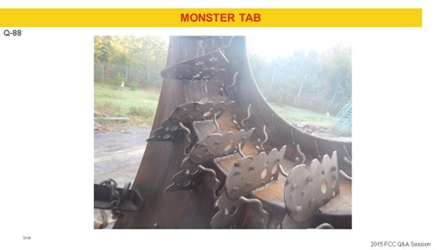
In extreme geometries, such as in the Y-piece or a bull nose, in cold-wall refractory, Shell usually uses what is called a monster tab, as shown on the slide, to anchor the system.
To prevent flow bypassing, as I mentioned previously, Shell uses what is called a vapor stop. You can see there that it is a ring of steel that goes around the vessel and protrudes into the refractory.
As far as poor refractory choice is concerned, in areas where you have severe erosion issues, you can obviously choose a more erosion-resistant refractory initially. Also, in areas where water sprays are a concern, it is important that you use a proper refractory, such as a fused silica thermal shock resistant refractory.
Regarding the repairs itself, a hot-wall repair requires complete removal of both the refractory and the hex metal in the affected area. Prior to reinstallation of the new refractory anchors, the metal surface must be prepared and cleaned, which means that it must be ground and power-brushed before welding onto the new anchors.
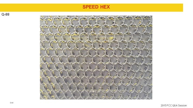
For large repairs, Shell typically uses curl anchors because using hex metal for a large repair is too time-consuming. For small repairs, Shell has had experience using speed hex. After the anchor is installed, you apply the new refractory. Here is a picture of some speed hex.
On cold-wall repairs, there is a similar repair method for both large and small repairs. Damaged refractory is removed back to the base metal (new cold-wall refractory is not put on top of the existing cold-wall refractory). For large repairs, the damaged refractory is cut back at a 90-degree angle to the metal surface. For small repairs, you can use an undercut, which will help lock in the refractory repair.
The metal surface for both large and small repairs must be cleaned and prepped, which includes grit blasting and grinding. If the metal or anchors are damaged, the old metal anchors must be completely removed and replaced. If there is a discontinuity in the repair area, which would be like a nozzle or something protruding the vessel, the refractory repair either has to completely surround the discontinuity or stop three anchors from the discontinuity. For both big and small repairs, three anchors need to be exposed for the repair to be successful. Once you have your anchors installed, the metal surface is wetted, and a new refractory is applied.
Year
2015
Process
Question 89: For an equipment revamp/replacement, what are the factors you consider when choosing between hot-wall and cold-wall refractory design, including advantages and disadvantages of each?
REYNOLDS (Phillips 66)
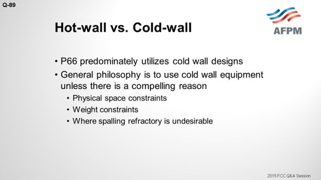
At Phillips 66, we predominantly rely on cold-wall equipment. Our approach is typically to use cold wall, unless we cannot use it for reasons I will discuss. There are situations where you are not able to use cold-walls, where the larger physical size of the cold-wall equipment cannot fit in the space allowed or if the additional weight requires too much structural steel modifications to fit it in.
Another circumstance where you may not want to use hot wall is upstream of the power recovery equipment where spalling off refractory is not good. So an option that I have heard described as a “warm-wall” is basically to have a cold-wall design in which you put a stainless-steel skin on the inside to minimize refractory spalling.
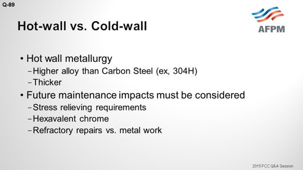
One of the issues with the hot wall is that the hotter temperatures force you into higher metallurgy of all the equipment. For carbon steel going from 650 to 1000°F, allowed stresses will go down by a factor of seven. The additional cost of that higher metallurgy will usually balance out with the refractory. We found that cost to be fairly comparable. Also, cold-wall metallurgy will not suffer from or be as susceptible to creep and sulfidation as will hot-wall metallurgy.
You need to keep future repairs in mind. The refractory repairs will require a dryout. But when you work on a hot wall, that hot work will often require expensive and time-consuming post-weld heat-treating. Also, the higher metallurgy may push you into a hexavalent chrome concern, so the workers performing the hot work will be in fresh air. If you are inside the equipment, everyone else in that vessel may have to be in the fresh air as well, which will slow down the work.
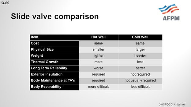
I included this comparison of slide valves, but it is applicable for fixed equipment as well. I have touched on most of these bullet points. We have had better reliability with cold wall slide valves. The slide says that for cold-wall designs, exterior insulation is not required; but it actually is typically not allowed.
FOSHEE [Shell Global Solutions (U.S.)]
Shell has experience with both cold-wall and hot-wall refractory designs for reactors and stripper vessels, but regenerator vessels are always cold-wall refractory designs. Depending on the reactor and stripper vessel, refractory type and standpipes, liftpots, and external portions of the riser can be either cold-wall or hot-wall designs. However, having said that, our current Shell standard is to use cold-wall design for all grassroots FCC projects for the design of all vessels, standpipes, liftpots, and external portions of the riser.
For a revamp FCC project, sections of the unit that are hot-wall are typically replaced with a hot-wall design unless the foundations and steel are improved to handle the additional weight of the cold-wall design. I will add here that for cold-wall refractory, one of our Best Practices is to stencil along the surface of the metal the words: “This is a cold-wall refractory. Do not insulate.”
Cold-wall refractory has several advantages over hot-wall refractory. First of all, you are able to use less expensive carbon steel for the vessel shell versus a more expensive alloy. In cold water refractory design, you do not have temporary embrittlement issues in the steel, whereas in hot-wall design, you can run into these problems. Also, external insulation is not only not required; it is absolutely not put on cold-wall refractory. Hot-wall refractory designs do need external insulation.
There are a few drawbacks to cold-wall designs. First of all, hot-wall refractory can be easier to repair, and it is faster to cure than cold-wall refractory. Secondly, hot-wall refractory is much lighter than cold-wall refractory. And thirdly, as I have mentioned before, putting insulation on the outside of cold-wall refractory design will cause problems with the vessel metallurgy that will eventually lead to metal failure, whereas hot-wall designs do not have this issue.
Year
2015
Process
Question 90: We are planning to purchase a new flue gas steam generator. What is your preferred configuration? What are the critical operating parameters you employ to ensure reliable operation? What is your sparing philosophy?
SINGH (Indian Oil Corporation Limited)
The configuration of the flue gas steam generator will be predominantly governed by FCC design. For a partial-combustion unit, it will be a CO boiler or a CO incinerator cum FGC (flue gas cooler) combination. For complete combustion, it will be a FGC or waste heat boiler alone. By CO boiler, typically we mean a boiler where the steam generating tubes are exposed to direct flame. On the other hand, in the case of a CO incinerator, CO is burned first to CO2 (carbon dioxide). These flue gases are then used to generate steam in the downstream FGC.
At Indian Oil, we have experience with all such boilers and flue gas coolers. Our experience is that the combination of a CO incinerator and FGC is much more reliable than a CO boiler by itself. All of our units have a bypass provision for an FGC. We do not have spare flue gas cooler in any of our units. Almost all of our units have a provision to put in blinds and spacers at the inlet and outlet of flue gas coolers to enable us to do maintenance without shutting down the FCC. The steam generation levels vary from 12 to 50 bars from unit to unit. Our experience is that the flue gas steam generators are more reliable at lower pressures of steam generation.
Preferred design of flue gas cooler is water-wall type in which the tubes are welded together to form the shell for the boiler with external insulation. Such designs have been found to be very robust and dependable. The common problems we have encountered include refractory and inlet bellow failures, boiler tube erosion, collection of catalyst at FGC bottom, and cold end corrosion due to condensed acid gas. Dry run of the tubes has been the leading cause of the tubes’ failure. Accumulated bed catalyst is acidic and highly corrosive. To overcome this, in most of our units we have modified the bottoms of these boilers to dump out the catalyst conveniently during the turnarounds, as well as during operation itself.
Going by the problems experienced in different CO boilers and FGC, the following can be considered for a new boiler design: The boiler design should have a provision for positive isolation to enable boiler maintenance. The boiler should be maintenance-friendly; that is, various pressure parts, economizers, and superheater coil bank tubes should be accessible. Soot blowers should be provided in high catalyst deposition zones and should be functional. We prefer to go for fabric bellows over the metallic bellows because of the frequent failure of metallic bellows in the flue gas line. The catalyst dump hoppers may be provided at the bottom of the economizer and superheater sections for regular and quick removal of the catalyst.
LARSEN [Marathon Petroleum Corporation (MPC)]
I think Sanjiv did a great job with the answer. I know that at Marathon, we only have one partial-burn unit with the CO boiler. Aside from that, we have several water-tube-style flue gas steam generators with shell-and-tube gauge exchanger design. In general, we have had good luck with them. We do not have provisions to take them off on the run, and they have not really caused us any reliability problems. We do have one unit with fire-tube-style flue gas steam generators. We are also satisfied with its reliability. So, there are definitely a lot of options: water- versus fire-tube and high pressure versus low pressure.
Maybe some of the licensors can comment. But if you are to trying to build a large new grassroots unit, perhaps the lowest-cost reliable option would be a low-pressure box-style boiler because you can possibly get away with just doing one of them. Making sure that the key point is to have reliable soot blowers. At Marathon, we did have a cause to evaluate replacing a couple of older designed waste-heat boilers with low pressure box-style. The unit did not have working soot blowers or anything. They were a significant cause of reliability problems for us, and replacing two old boilers with one newly designed unit was thought to be the best way to go. However, the fact is that when replacing equipment in a unit that was already designed with two boilers, the piping configuration, ducting, and structural loads made it more economical to go back with two new pieces of equipment instead of a single large boiler. At times, your hand is forced by what you currently have existing in your unit, in terms of replacement strategy.
RAMA RAO MARRI (CB&I Lummus Technology)
Nik and Sanjiv had summarized the answer nicely. I think, configuration-wise, that the horizontal type is better than the vertical, as Sanjiv recommended. It is a packaged item. As a licensor, we have some specified conditions and criteria that we establish. But mostly, the horizontal type is what we are seeing being used because it is accessible and easy to maintain and repair. So, we recommend the horizontal type.
SANJIV SINGH [Indian Oil Corp Ltd. (IOCL)]
For an FGC (flue gas cooler), the configuration will be predominantly governed by FCC design. For a partial-combustion unit, it will be CO boiler or CO incinerator and FGC combination; and for a complete-combustion unit, it would be FGC/WHB (waste heat boiler) alone. At IOCL, we have experience with all such boiler/FGC combinations. Our experience with a CO incinerator/FGC combination had been better in comparison to a CO boiler. Though all of our units have bypass provisions for FGC, none of the units has a spare FGC. Almost all the units have provisions to put blinds at FGC inlet and outlet to carryout maintenance while the FCC remains onstream. The steam generation level in FGC varies from unit to unit depending upon the overall steam balance of the refinery. We have steam generation levels ranging from medium pressure (12 bar) to high pressure (50 bar).
The preferred design for an FGC is a ‘water wall’ in which tubes are welded together to form the shell for the boiler with external insulation. Such designs have been very robust and dependable. Common problems encountered with the FGC include refractory failure, inlet below failure, boiler tubes’ erosion due to catalyst content of flue gas, collection of catalyst at FGC bottom, and cold end corrosion due to condensed acid gas. Dry run of the tubes leading to tubes failure had been one of the most common causes of failure. Accumulated wet catalyst is acidic and highly corrosive. To overcome this, we have made provisions to take out catalyst from the FGC bottoms even while the plant remains onstream.
Based on problems experienced in different COB/FGC, the following shall be considered in the new boiler:
-
The boiler design should have provisions for positive isolation to enable boiler maintenance even when the FCC unit is in operation. The main CO-flue gas duct should have isolation and blinding provisions with a similar arrangement at the stack end to ensure positive isolation of the equipment.
-
The boiler should be maintenance friendly; i.e., various pressure parts like economizers, superheater/bank tubes, etc. should be accessible. The catalyst and soot deposit can be easily cleaned during maintenance turnaround.
-
Soot blowers should be provided in high catalyst deposition zones and be functional. Catalyst carryover shall be monitored upstream of the boiler so that damage to the tubes and deposition can be minimized.
-
Metallic bellows have a history of cracking/failure, so fabric bellows shall be provided as far as possible over the metallic bellows.
-
Catalyst hoppers may be provided in the bottom of the economizer/superheater sections for regular and quick removal of catalyst.
NIKOLAS LARSEN [Marathon Petroleum Company (MPC)]
Flue gas steam generators can be a significant reliability concern for FCC units. However, if properly designed, operated, and maintained, they can also be an afterthought. In typical new grassroots units, a common design is that of a single, low pressure (downstream of flue gas slide valve) ‘box-type’ water tube flue gas steam generator (FGSG)/waste heat boiler. Unfortunately, we are infrequently handed a blank sheet of paper, and reliability improvements associated with current unit design, configuration, and plot space are desired. Still, improved reliability and increased heat transfer capability can be achieved by installing new FGSG equipment. There are a number of options to consider such as type (water tube versus fire tube), number (spared versus unspared), orientation (horizontal, vertical, box, etc.), and location of flue gas steam generator (high pressure versus low pressure).
Water tube FGSGs are generally more reliable than fire tube FGSGs. A water tube FGSG would be a preferred option if catalyst losses from the regenerator are low and flue gas velocities are also low (about 90 fps) as this type of exchanger is susceptible to erosion in highly loaded systems. MPC has several of these types of FGSG designs. There are a number of design features that can improve reliability in these designs, but they result in the need for additional exchanger length. These features include upgraded metallurgy of the fins and vapor belts on the inlet and outlet of the FGSG. Fin tip temperatures can exceed 1000°F so metallurgies like 1¼ chrome or 409 SS (stainless steel) should be investigated. We have found that using 1¼ chrome versus carbon steel fins has no significant impact on the overall heat transfer rate. A heat transfer coefficient of about 6 BTU/h.ft2.°F is adequate for a new FGSG of this design; a fouling factor of 0.03 ft2.h.°F/BTU for design is consistent with the operating data for a fouled FGSG of this type. It is also important to be cognizant of acid dew point concerns with all FGSG designs.
Another option to consider is a fire tube type of exchanger. In this exchanger, the flue gas is cooled on the tube side and the water/steam is on the shell side. There are certain critical design features that are essential for reliable operation in this type of FGSG, such as the upper tube sheet design and the water/steam outlet design. The critical hot top tube sheet is protected with six to 10 inches of insulating refractory. Inlet tube ferrules (typically ceramic or stainless steel) extend through the refractory and into the tubes. For a vertical design, the flue gas enters the top of the exchanger. This can be a positive feature of this type of exchanger depending on inlet piping configuration as the potential for erosion is lessened if there are no changes in direction of the flue gas.
A downside to this design is that the tube bundle is non-removable and that all inspection and maintenance must be done in place. MPC does not have any vertical fire tube FGSG designs. However, we do have a unit operating with a horizontal fire tube-type FGSGs and have had good operating experience. Horizontal fire tube exchangers have good cooling of the hot tube sheet. The tube sheet is self-venting, which prevents the accumulation of noncondensables that can collect under the tube sheet in a vertically oriented fire tube exchanger. Piping arrangement and scouring may be more challenging for horizontal fire tubes (compared to vertical fire tubes). Heat transfer coefficients are comparatively higher than water tube designs (11+ BTU/h.ft2.°F), and hot side fouling factors are slightly lower (0.02 ft2.h.°F/BTU).
Depending on the size of the unit and amount of heat recovery desired, a single piece of equipment in the above designs can be large – often too large, which can lead to consideration of a low pressure ‘box type’ FGSG/waste heat boiler; these are unlike the previous designs that are closer to a shell-and-tube heat exchanger. The type of FGSG being replaced can often be a deciding factor as well due to the surrounding piping/duct, foundation, and plot space. MPC recently encountered this while deciding on a replacement strategy for a large unit with two old low-pressure box-style waste heat boilers. In the end, installing two newly designed low-pressure box-style waste heat boilers were the most cost-effective option. In large part, this was due to unit piping configuration, plot space, and ability to install equipment while the unit was in operation. Critical factors for successful future operation on this unit included soot blower design/reliability and ability to operate without waste heat boilers (quench system).
PATRICK BERNHAGEN (Amec Foster Wheeler)
Larger FCC units have basically two types of steam generation methods: forced circulation and natural circulation. In both of these designs, the regenerator flue gas is on the outside of the heat transfer tubes. Amec Foster Wheeler offers both designs.
Our natural circulation design has vertical tube bundles for the various services with the steam drum above them. The flue gas flows across these bundles horizontally similar to an HRSG (heat recovery steam generator). Hoppers are below the bundles to collect any catalyst dust that drops out of the flue gas stream. Various levels of soot blowers are placed along the flue gas path and vertically along the tube bundles to keep the heat transfer surface free of fines. The circulation ratio is carefully selected to accommodate the required steam pressure level and tube bundle design. Economizer, steam generation, and steam superheat are typically the services in the unit.
Our forced circulation design has horizontal tubes very similar to fired-heater convection sections stacked on top of each other for the various services. Circulation of the BFW (boiler feed water) through the steam generator coils is provided by circulation pumps (typically spared). This design has a higher flue gas velocity through the heat transfer coils and entrains the catalyst fines such that hoppers are not necessary. Again, various levels of soot blowers aid in moving the dust through the unit while keeping the tubes free of deposits. This design has successfully used low density finning with proper soot blower arrangements.
General conditions of the flue gas steam generator to consider include the following:
Operating and design pressure of the casing (enclosure) needs to consider the back pressure of the system. This is typically in the range of 25” WC (water column); but if wet scrubbers are in the system, this number can increase substantially. Units up to 5 psig (pounds per square inch gauge) design pressure have been built, but there is a premium for higher pressures.
Catalyst loading and deposition must be addressed. Our natural circulation systems are designed with hoppers to collect any catalyst fines and must be periodically cleaned out. Our forced circulation designs with higher flue gas velocities do not need hoppers. Retractable soot blowers (no rotary) should be selected for their robustness. Another key component is the wall boxes/valves on the casing for soot blower entry and sealing when soot blower retracted. Poor designs allow leakage and can affect operations.
Plot Space is critical on a retrofit installation in most cases. The natural circulation style can require a larger plot space as it is horizontally arranged coils with design constraints on lengths and widths. The forced circulation design is vertically oriented, thereby reducing the plot space requirements. The circulation pumps do not necessarily need to be adjacent to the unit thereby allowing another degree of plot space flexibility.
Steam quality/purity/superheat is another topic requiring your specification. Our steam drum design can address the superheated steam at any pressure level. Our drums have primary and secondary separation devices or more depending on your requirements.
Turndown operational requirements need to be specified with any steam demand requirements. Forced circulation systems respond to load swings more rapidly as there is always flow through the tubes.
Vibration analysis/cold flow modeling/CFD modeling are topics to discuss with the various designs. Vertical tube designs will analysis the entrance flow distribution and tube support along the coil length. Horizontal tube designs with large (~4” NPS) tubes typically only require flow distribution analysis. Support is usually determined by API 560 requirements.
Refractory selection must be made considering the catalyst fines abrasiveness and the sootblowing frequency. Depending on the style of flue gas steam generator, there are a small variety of hard refractories that are used.
CHRIS STEVES (Norton Engineering)
A number of reliable technologies are currently being employed in flue gas steam generator service. They include: two drum vertical tube natural circulation boilers (water/steam on tube side), horizontal and vertical tube forced circulation boilers (water/steam tube side), and fire tube steam generators (flue gas on tube side). There is no one right answer for selection of a specific technology or equipment design for all applications as they all are demonstrated technologies available from reputable vendors. They all have pros and cons which must be weighed to determine the “best” (most economical) fit for a specific application. More often than not, constructability, space availability, and the cost of ancillary components and systems determine the optimum technology for a specific application.
Natural circulation WHBs are the simplest units, are easy to operate and have the lowest overall operating cost. They use the same manufacturing techniques and standards as fired-water tube boilers, so they tend to be highly reliable and are not normally spared. The only reason to spare this type of WHB would be to meet mandatory state/insurance inspection requirements if they require boiler component inspection on a more frequent cycle than planned FCC turnarounds.
Forced circulation boilers, typically horizontal tube units, in up-flow or down-flow flue gas configurations, are also highly reliable and rarely spared. This type of system uses external pumps to circulate water through the tubes of the steam generation bank instead of relying on natural circulation. The steam drum is normally separate from the tube bank and has many fewer connections than a natural circulation unit, making it less complex but also likely larger in diameter.
Circulation pumps are typically spared with one driven by a steam turbine and the other by an electric motor. Autostart is provided to prevent loss of flow to the WHB. The “rectangular duct” enclosure of forced circulation WHBs makes them easier to clean than natural circulation units and therefore less prone to external corrosion during FCC outages. Superheater and economizer coils can be included in rectangular duct systems at lower cost than non-rectangular duct designs.
The WHB types described above (flue gas cooling across a bank of tubes) all require soot blowers to maintain performance. Soot blower equipment, by itself, is not expensive, but soot blowers need significant infrastructure to operate – namely; steam and seal air – and require significant maintenance resources to maintain reliable operation and reliable WHB performance. Loss of effective soot blower operation results in higher flue gas discharge temperature. In the past, when FCC emissions control was not as prevalent as today, this increase in temperature was a purely energy conservation concern which did not adversely impact FCC operation. With current governmental focus on emissions reduction, specifically NOx emission reduction using SCR technology, it is now necessary to control the flue gas temperature at the outlet of the WHB, elevating soot blower maintenance from a routine, non-critical activity to a critical activity to maintain the FCC in operation.
Two types of steam generating flue gas coolers which do not require soot blowers for cleaning are commercially available. The first type places flue gas on the tube side and boils water on the shell side. These steam generators are fixed tube sheet designs and are installed in an inclined position with the flue gas flowing “downward” along the exchanger and steam exiting the upper portion of the shell. The inlet tube sheet is refractory lined, and the inlet of each tube is fitted with erosion-resistant, replaceable ferrules for erosion protection. The steam generation section is natural circulation, and units are not normally spared. Superheater and economizer coils cannot be integrated into this type of equipment. To include these features, separate duct coils and enclosures are required. High pressure steam (600 psig and higher) is normally generated in these units to avoid acid condensation on the inside of the tubes.
The second “cleaning-free” type of commercially available unit is a longitudinally finned vertical tube bundle with water/steam on the tube side and flue gas on the shell side flowing in “rectangular” passages formed of ¼ tubes and fins. Steam generation on the tube side of these units decreases the thickness of the shell versus a shell-side boiling design. Vertical hairpin steam generation coils require forced circulation of water to the steam generation coil. Longitudinal finned superheater and economizer coils are readily integrated into the system. Due to the complexity of the design, compared with an inclined “fire tube” design, this type of unit is normally supplied with an installed spare.
Both “cleaning-free” units require steam drums to be installed adjacent to the steam generator. Although permanent soot blower facilities are normally not needed for the “cleaning-free” type of steam generators, facilities for injection of cleaning material (such as walnut shells) should be provided.
The steam generator technology selection decision will be a project-specific one considering the level of steam to be generated, the available space for constructing the steam generator and ancillary equipment during FCC operation, the delivery time for equipment, the cost of flue gas ducting to the new SG(s), the cost of piping to and from the new SG(s) location, etc. A side-by-side assessment of the four SG alternatives is recommended to ensure you obtain the technology which fits your FCC.
Year
2015
Process
Question 91: What are your top three causes of unit slowdowns, and what is the loss in onstream factor for each? Please provide the same information for your top three causes of unit shutdowns.
RUSSEFF (CVR Energy)
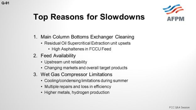
I get the fun one! For us, it has been the main column bottoms exchanger cleaning. We have a residuum oil supercritical extraction unit, or ROSE unit, upstream. We have been achieving some new recoveries there and are ending up with the high asphaltenes in our feed and in our slurry; so, slowdowns are the result of the combination of that polynuclear aromatic formation. Some people get excited over 15% asphaltenes in their slurry. When the ROSE is not online, we go from about 3% up to as high as 40%, which is very discouraging. A typical turndown for replacing a bundle in that service is about 75% max capacity. We have a spare steam generator online, so we could switch back and forth between the two units.
Feed availability: In our Wynnewood Refinery, we have competition for feed, depending upon the market conditions. In Coffeyville, we do not necessarily have a competitor for that feed within the refinery itself. But due to the kind of positioning and some of the prices we have seen, in terms of premium gasoline and diesel, we have changed some operations. So, we are just trying to make up for that price fluctuation in other areas for the gasoline crack. We have also been able to locate opportunity feed from some external sources. We have good synergy between the two refineries, and they are relatively close. So, when the northern one was going into a turnaround, we managed to turn through a lot of their gas and oil this year, too. So, the answer on turnaround is: It varies, depending upon the market.
Our Limitations on Our Wet Gas Machine: We have a dry screw machine in wet gas service. This is a first for me, and it has been a painful process. We have had a couple of outages because of problems with the dry screw machine in wet gas service, but we have a current rebuilding that has some losses in efficiency. We do have a backup machine: a reciprocating compressor. However, we have a considerable turndown; basically, down to 50%. Additionally, for upstream unit recoveries, such as the ROSE I mentioned earlier, we are turning up the knob on recoveries and the asphaltenes. Conradson carbon residue (CCR) leads to metals taking capacity in the wet gas machine with a higher hydrogen and methane ratio. We have been aggressively flushing the additional metals in the catalyst. I have also switched over to a nickel trap catalyst, which is working well.
Also, in our Oklahoma and Kansas facilities, with the lack of condensing and cooling capacities they have during the summertime, the loss in capacity is really directly dependent on the ambient conditions outside. So that turndown depending upon how hot it is outside at each moment.
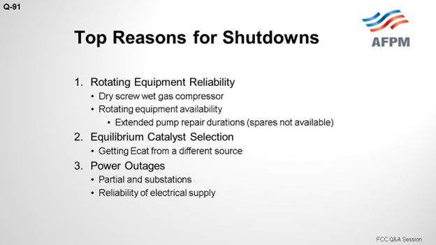
As far as the top three shutdowns, I have to say that the rotating equipment reliability, especially with the dry screw machine, has been difficult. We have a spare machine. It is a reciprocating wet gas machine, but it just does not have the capacity. We do not actually have a full shutdown. You would think that some of the parts on that dry screw machine were made of fresh panda blood because it is very difficult to get parts for it.
We have also had some other problems as we have gone through a rigorous pump rebuild program where we sent pumps out to have complete rebuilds so we could start a new benchmark, in terms of reliability. That does take more time. The pump availability for the spares has not been there during this revamp of our reliability program, so we have had some issues there.
Finally, the other main reason for shutdowns is probably the catalyst. It is a very sensitive subject, but it is more of a catalyst issue. We had the opportunity to run some what I would call opportunity e-cat. Right now, I want to say that we are really happy with our long-time vendor, but running the opportunity e-cat from somewhere else was not such a good opportunity. The shutdown gave us a chance to prove that our current vendors are probably the best out there. It also gave us a chance to communicate wonderful experiences about paying attention to your e-cat, no matter where you get it from, to the additives, activity, metals, particulate size, yield projections, and required addition rates. So, those are our top three reasons for shutdowns.
SINGH (Indian Oil Corporation Limited)
The cat crackers are one of the major secondary units for all of our refineries. Irrespective of demand and condition, our units are always required to operate at high capacities. All of our refineries have been participating in benchmarking studies done by Solomon. I tried to compile the Solomon studies results for 2014, which are shown on the slide. They are based on more than 300 cat crackers worldwide. As can be seen, the last one is for Indian Oil Refineries. We have eight cat crackers. You can see the slowdown percentage for our units is much lower than the global numbers. Our refineries are focused on consistent high-capacity performance of the FCC units.
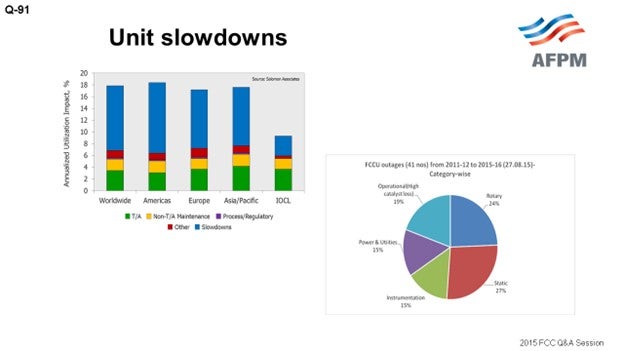
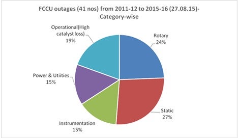
Referring to the FCC outage pie chart for IOCL refineries, it can be noticed that there is no single reason for unplanned outages on our units. Our youngest unit is 13 years old. Typically, most of the units are between 17 and 32 years old. All these units have been revamped to capacities more than 25% to about 50% of the original design capacities.
The pie chart presents the distribution of the different reasons for our plant interruptions. I have tried to compile data for the last five years. There are a total of 41 incidents, and I cannot figure out a single reason that has been predominant. We operate our units based on our captive power plants. So, this power and utilities interruption of 15% is based on our own power plant. The catalyst loss issues are predominantly because of reactor/regenerator internals and the aging of these internals, not because of any other issue. The rotary equipment issues are predominantly WGC failures. None of the refineries have a spare WGC. And similarly, the static and instrumentation issues have shown 27% and 15% of total outages, respectively.
It needs to be noted that while presenting the interruption data for our FCC units, all interruptions – irrespective of the duration – have been included in the evaluation. Any incident that leads to a feed out has been accounted for in these statistics.
LARSEN [Marathon Petroleum Corporation (MPC)]
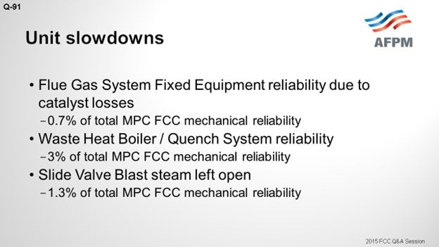
I tracked internal problems associated with our FCCs and the reliability impact of these for all of our Marathon FCCs. I highlighted a couple of our top three. Because the question mentioned onstream factor, our three biggest ones for the first two entries are from 2014; the last one was 2015. The flue gas steam generator leaking caused 0.7% loss in our total Marathon FCC reliability. That is basically due, as was Sanjiv’s experience, to the old cyclones on this site. We chose to operate it at higher velocities than our normal operating guidelines, which resulted in higher catalyst losses and impacts on this flue gas steam generator.
The second one is the waste heat boiler situation I mentioned before: previous old CO boilers converted to just normal waste heat boilers now. An improper quench design where the boiler feed water is injected too close to a geometry change in the flue gas line resulted in significant erosion and corrosion problems. That resulted in a low of 3% total Marathon FCC mechanical liability in 2014, and the correction there is for installing our new waste heat boilers on this unit in the future.
The last one occurred in 2015 and was an unforced error from leaving blast steam open on the guides on the spent slide valves, resulting in the loss of control on the reactor level. We have shown the damage that that can do in a fairly short period of time.
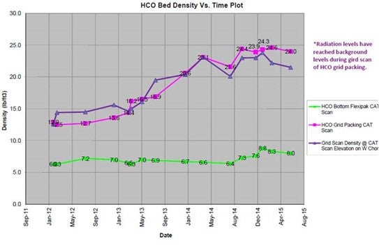
In terms of slowdowns, I just want to add one interesting example. We have one unit that is challenged in the fractionator, in terms of coking. It required the reduction in throughput to manage this coking, but you can see that we tracked the densities. In the packing, you can see that the green trend is the tracking of the density in the top layer. The other two are in the bottom layer of the pack. You can see the densities creep up over time.
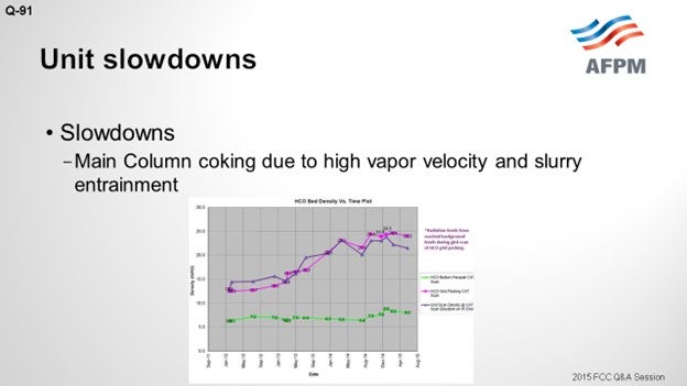
So, this is a strategy we use to manage getting to the next turnaround where we can properly swap some of the fractionation beds. This unit has high inlet velocities to the fractionator and high slurry entrainment, combined with the fractionation section being located right above the slurry section, with the resulting low liquid rates contributing to the coking problem. So ultimately, we are swapping the beds around in the fractionator to eliminate that concern.
JAMES (JIM) PROROK (Husky Energy, Inc.)
I was not going to say anything on the last question; but on this one, you again brought up the waste heat boilers that sometimes reduce liability. On our unit, the mud drum hangs on the bottom of the tubes inside the flue gas duct, so you cannot get to it very easily. Regarding the gaskets, we had the manway gaskets on the mud drum. You could tell it was happening by the water balance on the boiler. So yes, not that it is a bad design, it is just that when you do maintenance of your unit and have startup and shutdown, the thermal cycling of the system may cause the gaskets to leak. It may have stretched bolts and leaked where the gaskets were crushed and then cooled off, ending in failure.
SANJIV SINGH [Indian Oil Corp Ltd. (IOCL)]
FCC/RFCC units are the one of the major secondary units in almost all of IOCL’s refineries. Irrespective of demand positions, these units are always required to operate at high capacities. All of our refineries had been participating in the benchmarking surveys conducted by Solomon Associates, and the results comparing IOCL FCC units with rest of the world (2014 study) are indicated below. The chart shows the factors impacting FCC unit capacity utilization. This chart considers the data reported for approximately 300 FCC units in recent Solomon Fuels Refinery Performance Analyses (Fuels Studies).
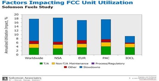
IOCL refineries are focused on achieving consistently high-capacity performance of its FCC units. Regarding unplanned outages, there is no single reason for the same. The age profile of operating FCC units varies from over 30 years to little over 10 years, and failures mainly with reactor/regenerator had been due to aging equipment. Unplanned outages of FCC units during the past five years are indicated below.
NIKOLAS LARSEN [Marathon Petroleum Company (MPC)]
Rationalization of U.S. refining assets has placed significant focus on doing more with less while meeting tougher environmental and regulatory requirements. This has created incentives for improving FCC reliability: The unit needs to run to make a profit. MPC’s take on this is captured in our FCC business plan, which is based upon the following pillars:
- Build it right. Invest in the right hardware to modernize and capture the latest technological and reliability improvements.
- Optimize and debottleneck. Continuously focus on operating up against multiple constraints and completing small tests/projects to creep limits.
- Run it to last. Stay inside the box with regard to procedures, limits, and KPIs (key performance indicators).
Using this model has (historically) resulted in greater than 98% mechanical availability for MPC FCC units. However, there is always room for improvement. In general, MPC seeks to lower cyclone velocities in order to minimize erosion without sacrificing efficiency. This, along with longer L/D (length over diameter), has improved dustbowl erosion. However, in situations where dipleg length is limited, MPC will be installing new cyclones with vortex stabilizers to avoid extending the regenerator vessel to accommodate larger cyclones. Cyclone reliability was responsible for reducing overall FCC mechanical reliability by about 0.7% in 2014.
Likewise, cyclone L/D ratio can affect waste heat boiler reliability. To minimize flue gas and tube leaks going forward, new waste heat boilers will be installed, and new cyclone technology (vortex stabilizers) will be evaluated as driven by unit configuration/design. Waste heat boiler reliability was responsible for reducing overall FCC mechanical reliability by about 3% in 2014. Third, proper blast steam operation minimizes slide valve guide erosion. Slide valve erosion reliability was responsible for reducing overall FCC mechanical reliability by about 1.3% 2015.
Lastly, main column coking in the fractionator section can be caused by high vapor velocity and slurry entrainment combined with low liquid rates in the fractionation section above the slurry pumparound bed. Reducing fractionator inlet velocity and redesigning fractionator bed placement to eliminate a fractionation bed between slurry and HCO pumparound streams is expected to reduce coke formation.
GARY HAWKINS (Emerson Process Management)
We have seen increased interest in monitoring any rotating equipment, such as process pumps and air-cooled exchangers, which can allow early detection of potential problems that could cause a shutdown or upset. The major equipment, like the air blower and wet gas compressor, is typically supplied with shutdown systems, but the air blower and wet gas compressor do not necessarily have all the measurements to calculate performance, such as efficiency and alert when efficiency deteriorates, which can be an early indication of a potential shutdown.
Year
2015
Process
