Question 76: What FCC operating, and catalytic changes can lower gasoline sulfur while retaining octane? How would feed hydrotreatment impact these options? How would the FCC operate and catalytic changes impact gasoline post-hydrotreating?
ZACH BEZON [United Refining Company (URC)]
The following changes can be done to lower gasoline sulfur and retain octane:
1.Lower gasoline endpoint
2. Increase main fractionator reflux rate
3. Increase matrix activity,
4.Increase cat-to-oil, or
5.Use an additive, such as D-Prism, to shift sulfur away from gasoline
Hydrotreating the entire FCC feedstock upfront will allow more flexibility in operation of the reactor/regenerator. Delta coke will decrease with a hydrotreated feedstock, which will lead to a colder regenerator and will drive a higher cat-to-oil ratio. Increasing cat-to-oil will directionally increase both gasoline yield and octane number. Hydrotreating will also decrease metal contaminants, which will directionally reduce the amount of hydrogenation reactions, and lead to an increased octane number in the gasoline pool. Overall, FCC gasoline octane from a unit with hydrotreated feed should be a few points higher versus having a sour feed and hydrotreating the gasoline products.
Any operational or catalytic changes that directionally reduce your gasoline sulfur will make downstream hydrotreating easier (less severe). This sulfur reduction can lead to longer hydrotreater life via reduced operating temperatures and delta T.
ALEXIS SHACKLEFORD (BASF Corporation)
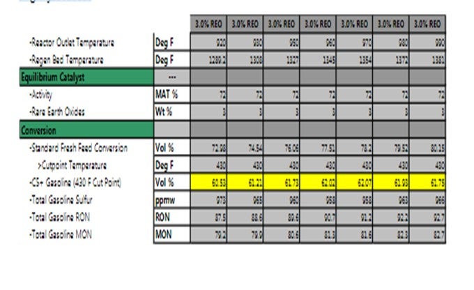
Here, the effect of catalyst changes and ROT (riser outlet temperature) are explored. As shown in table below, at constant ROT and constant catalyst activity, a low rare earth oxide (REO) catalyst will boost gasoline octane but will also increase gasoline sulfur. These data were obtained by KBC modeling at constant conditions.
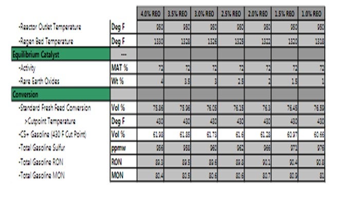
The effect ofROT on gasoline octane and sulfur content are shown in the next table. By raising ROT, gasoline octane will increase while gasoline sulfur content is estimated to be slightly reduced.
Refineries should work with catalyst suppliers to optimize operating conditions and catalyst properties to reach multiple goals within constraints.
Question 77: What are your Best Practices for mitigating operational or performance risks throughout a catalyst changeover?
REBECCA KUO and SHAUN PAN (BASF Corporation)
It is understood that there are risks when changing catalysts. Objectives and constraints might change during the trial, or changes in operating conditions might skew expected performance. BASF employs an in-house risk minimization process in which we work very closely with the refinery to understand the unit is risks and identify mitigation measures to reduce those risks if they occur. Examples of risks are sampling issues, non-optimized catalyst activity, changing objective due to another unit outage, or limited quality operational data. Once all risks are documented with the refiner's input, BASF identifies potential causes, consequences, and mitigation steps for each specific problem. It is also important to identify follow-up actions and the follow-upowner (whether it should be the catalyst supplier or the refinery). It is important to regularly send e-cat and fines samples to your catalyst supplier before and during the catalyst changeover. If there is an operational or performance issue, having a baseline of activity, physical, and chemical properties will help troubleshoot the root cause of the problem. BASF has successfully used this process in multiple refineries that have been on another supplier for a number of years, both for new product trials and established catalyst technologies. In either case, the risk throughout the catalyst changeover is minimized so efforts can be diverted to process improvements and optimization.
Question 78: What operational and catalytic changes have you implemented to optimize C4 olefin yield for the alkylation unit?
YORKLIN YANG (BASF Corporation)
The right choice of catalyst can help to improve C4 selectivity in an FCC unit including:
1. A catalyst with reduced rare earth oxide (REO), which will make more C3s and C4sbut preferentially increases butylene, and
2. A catalyst with absolute lowest possible sodium content, which will also increase butylene production over propylene.

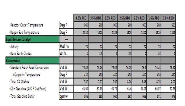
A low REO of less than 1% can yield a higher C4 olefinicity compared to catalyst of higher REO at constant conversion. However, as conversion increases, C4 olefinicity will decline. This is demonstrated in KBC modeling, shown below.
Another change is increasing riser outlet temperature (ROT). This is one of the most common adjustments to increase the production of olefins. Raising riser temperature favors production of butylene over propylene.
Lastly, to optimize C4 olefins, a refinery can optimize its ZSM-5 addition rate. ZSM-5 additives preferentially produce propylene. Typically, 60% of the incremental olefins will be propylene and only about 30% will be butylene. If using a ZSM-5 additive, by reducing the amount of ZSM-5 addition, you will increase butylene selectivity. There are also discussions in the industry on specialized ZSM-5 to increase butylene selectivity (1:1 increase versus 2:1 increase, depending on the amount of rare earth in catalyst)
Question 79: What methods do you use to detect and monitor coke deposition in FCCU risers? What prediction methods have been successful?
PHILLIP NICCUM (KP Engineering)
While coke deposition in reactor void spaces and overhead lines has been reported with some regularity, coking in risers is less common. Increasing riser pressure drop and decreasing riser shell temperatures provide an indication of riser coking, but gamma ray scans are the surest online indication of riser coking.
We are aware of two FCC units that have experienced severe coking in the riser feed injection zone where the catalyst and vapor velocities are lowest, and the vapor molecular weight is highest. The extent of the riser coking in both instances was enough that the increasing riser pressure drop, reduced catalyst valve differential pressure and increased catalyst valve opening so limited unit run lengths. In one case, gamma ray scans were conducted every month or two along the length of the riser, clearly identifying the location of the coking and correlating well with the observed thickness of the coke deposits.
Surface thermography has also been used successfully to indicate significant coking in the riser. Normally, the riser shell would be hottest below the feed injection elevation and steadily decline at higher elevations as the feedstock is vaporized and cracked. If the shell temperatures just above the feed injection location decline abruptly to lower-than-typical valuesbut then increaseto typical values at higher elevations, then coking in the lower riser section may be indicated.Riser coking is thought to be due to some combination of the following factors: heavier feed, higher feed zone pressure, lower dispersion steam rate, reduced catalyst circulation, lower feed zone temperature, poor catalyst distribution within the riser,and ineffective feed injection.
Question 80: What is your Best Practice for removing feed nozzles during turnarounds when only the tips are planned to be replaced? Are there any pros/cons or advantages/disadvantages of removing the nozzles while the system is hot or after it has cooled?
PHILLIP NICCUM (KP Engineering)
The answer to this question depends on the installation details of the feed nozzle with the riser sleeve. Three common types of installation are (1) steam-purged annulus, (2) refractory packing installed from inside the riser, and (3) compressible material around the nozzle tip installed externally before the nozzle is placed in the sleeve. The steam-purged annulus utilizes a small flow of steam between the feed nozzle and riser sleeve to keep coke and catalyst from accumulating in the annulus during the run. This system allows the nozzle to be removed from the riser without entering the riser. The system of packing refractory around the nozzle tip from inside the riser does not allow for removal of the feed nozzle without first entering the riser to carefully chip out the refractory. After new or refurbished nozzles are installed, the refractory must be reinstalled from within the riser. The system using compressible material around the nozzle tip allows the nozzle to be extracted from its sleeve without entering the riser. The system relies on the material around the tip compressing and sealing the nozzle against the sleeve when the nozzle flange to riser sleeve flange bolts is tightened. When new or refurbished nozzles are installed, new compressible material must be installed around the nozzle tips.
All of these systems work well most of the time; but at times, there can still be problems extracting the nozzles from the sleeves. A common first line of attack in removing a nozzle from a sleeve is to utilize threaded holes in the nozzle flange that are used with “jacking screws” to break a nozzle loose after it is unbolted from the sleeve. Once the flanges are separated enough to allow it, hydraulic flange spreader “alligator "jacks have been used to further separate the flanges. Twisting forces applied with a suitable leveraging device can also be used effectively to speed the removal processes. Chain hoists and cable pulls are not suggested for pulling stuck nozzles as the lines of force and stiffness of these system are not generally adequate. Preparation by gathering the materials, procedures, and tools required –beforehand –to extract a difficult nozzle is the key. During the process of removing the nozzles, safety considerations require that the nozzles be tied off so they cannot fall from the sleeve. Care should also be taken not to damage the nozzles with direct hammer blows or refractory chipping guns. If the purge steam is wet, which is not normal, and water droplets are allowed to impinge on a stainless-steel feed nozzle during the course of a run, the insert can be destroyed and deform to an extent that removal of the nozzle from the sleeve becomes practically impossible.
We are not aware of advantages in removing the nozzles when the unit is still hot beyond the savings of time spent waiting for the unit to cool. Typically, by the time the catalyst is unloaded from the reactor, regenerator, and riser bottom and manways are opened, the nozzles will be cool enough to handle safely from outside of the riser. And at that time, the probability of hot catalyst escaping from the riser sleeve has been eliminated.
Question 81: What is your inspection Best Practices for third-stage separator (TSS) systems throughout a scheduled turnaround? What types of issues or equipment damage should be would you proactively anticipate in order to mitigate potential turnaround delays?
BOUGRAT (Honeywell UOP)
For TSS systems, it becomes important to start by monitoring the operating conditions and process velocities throughout long-term operation to help anticipate the extent of erosion and internal wear of the equipment. Some refiners track velocity hours for the individual cyclones or barrels while others simply track onstream time to help predict when some of the equipment may ultimately fail. But overall, the system should be treated fairly similar to reactor-regenerator cyclones. Make sure you are optimizing the operation, staying within the velocity guidelines and helping mitigate any carryover from your upstream cyclones to the TSS. The TSS may be able to handle increased losses from the regenerator, but long-term operation under these conditions will inevitably lead to increased erosion of the internal components.
With regard to internal inspections, it becomes important to visually inspect all of the barrels and internal equipment on an individual basis. These inspections should include any blanked-off or spare equipment as well. For example, any spare equipment or blanked-off cyclones that serve as future contingency options should be inspected for adequate weld reliability and isolation quality to ensure that they will be properly preserved until needed. In general, any internal equipment or component that is immediately exposed to the incoming flow of flue gas and entrained catalyst fines will be the most prone to erosion. Therefore, sufficient spares should be provided for these components, which can be accomplished through a mix of warehouse and in situ (blanked-off) spares. If the internal components such as cyclones or barrels are large in number, UOP recommends sparing at least 10% of the total inventory.
To summarize, the long-term maintenance plan for TSS systems should include comprehensive monitoring of the process conditions and velocities, leveraged by historical field inspections, to help monitor the conditions of the internal equipment and help predict the necessary maintenance activities throughout subsequent unit outages.
PUI-NANGLIN (Flint Hills Resources)
Does anyone do a pressure test on their cyclones during turnarounds? How do you ensure the integrity of the cyclones during final inspections to confirm that they are pressure-tight or not?
BOB LUDOLPH [Shell Global Solutions (US) Inc.]
My experience relates only to regenerator cyclones when we were trying to track down a catalyst loss. At the time, we went into theunit and saw nothingthat could explain the problem. We restarted the unit; and again, there was a catalyst loss. We shut down and re-entered the regenerator with the plan to pressure-test the cyclones. To test the cyclones,you need to install a bladder in the cyclone dipleg,along with blank-offs on the cyclone outlet and inlet,with the means to add pressurizing air and pressure reading gauges.