Question 19: What is the maximum recommended nitrogen content of reformer feed for continuously regenerated units? What is its impact on chloride consumption and ammonium chloride generation?
LAMBIE (KBC Advanced Technologies, Inc.)
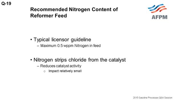
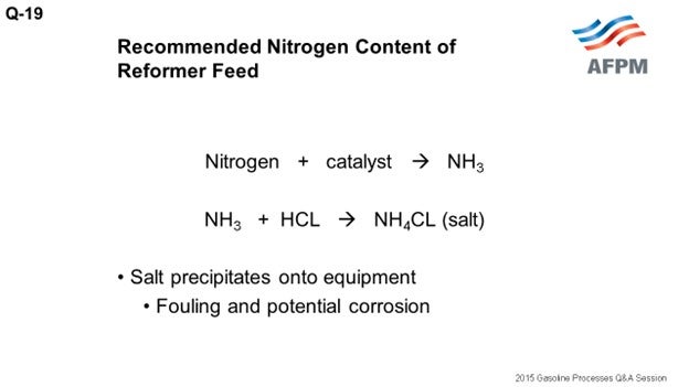
The typical licensor guideline is 0.5 ppm maximum nitrogen in the feed. When nitrogen contacts the catalyst in the reforming unit, it essentially strips chloride from the catalyst. The reduced chloride on catalyst results in reduced catalyst activity. However, in most instances, the impact on the activity is not substantial. For example, 0.5 ppm nitrogen in the feed will reduce the catalyst chloride content by 0.02%. To put that in perspective, each ppm of nitrogen in the feed results in a reduction in catalyst chloride of about 0.003%; so the impact is fairly small. Nitrogen converts to ammonia upon catalyst contact, and the ammonia will react with hydrogen chloride in the recycle gas to form ammonium chloride salt.
The salts that form will precipitate onto equipment, which will lead to fouling and potentially corrosion. The most common areas are the stabilizer trays where periodic waterwashing is required, but salts can also accumulate in compressors and fuel gas burners, as well as on combined feed exchangers, product condensers, and chloride guard beds. Some units can tolerate higher levels of nitrogen in the feed up to 0.5 ppm, while others have salting and fouling issues with 0.2 ppm nitrogen in the feed.
Basically, each refiner’s ability to handle the salt formation in the unit will dictate the tolerable level of nitrogen in the feed. In other words, the guideline is not meant for catalyst activity purposes but more for salt handling considerations.
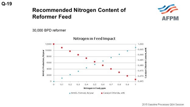
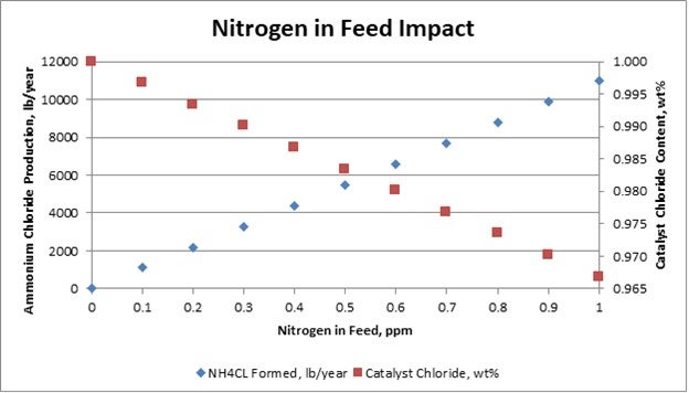
The ammonia produced, as I mentioned, reacts with HCl (hydrogen chloride) in stoichiometric balance. From that stoichiometric equation, you get the following relationships: 0.1 ppm nitrogen to feed produces 3.8 pounds of ammonium chloride salt. Or if you want to look at a different way, 0.1 ppm nitrogen to feed produces about 1,100 pounds of salt a year for a 30,000 barrel-per-day unit. And for every pound of nitrogen in feed, about 2.5 pounds of chloride is consumed or stripped from the catalyst. To put that in perspective again, 0.1 ppm nitrogen in feed results in a 0.003 reduction in the catalyst chloride content.
The plot on this slide shows the relationships of nitrogen in feed to salt formation and chloride consumed.
JUSTIN IRICK (GE Water & Process Technologies)
Do you have any experience with nitrogen speciation? Is it your opinion that all of the nitrogen in the feed converts to ammonia in the CCRs or does some sneak through?
LAMBIE (KBC Advanced Technologies, Inc.)
It has been my experience that most or all of the nitrogen in the feed gets converted to ammonia.
RATHINA SABAPATHI [Kuwait National Petroleum Company (KNPC)]
Do you have any information about the nitrogen content in advanced residue disulfide naphtha, which is the naphtha, because of the nitrogen turning pink? We are worried about that naphtha and would like to know if any speciation or anything else is done for the naphtha that comes from the residue hydrotreaters.
LAMBIE (KBC Advanced Technologies, Inc.)
I do not have experience with speciation of the nitrogen components in the naphtha boiling range from residue hydrotreaters.
SCOTT LAMBIE (KBC Advanced Technologies, Inc.)
A) The typical maximum recommended nitrogen content in reformer feed is 0.5 ppm. Nitrogen in the feed, when contacted with the catalyst, strips the chloride from the catalyst and converts to ammonia, NH3. The directional impact is reduced chloride on the catalyst and essentially lower activity due to the lower acidity.
In typical operations, the impact of the activity loss is not substantial. For example, the amount of chloride removed from the catalyst, assuming 0.5 ppm nitrogen in feed, is equivalent to reducing the chloride content by less than about 0.02 wt% (weight percent), or from 1.0 wt% chloride on catalyst to 0.98 wt%. The regenerated catalyst after additional chloride makeup is returned to 1.0%. A summary of the impact on catalyst chloride content is shown in the table below.
Nitrogen in the feed is typically managed more for salt production and fouling issues within the reforming unit than for catalyst activity debits. The salts that form will essentially wash through the system but will also accumulate in some of the equipment causing fouling; and in extreme cases, underdeposit corrosion. Some reforming units with feed nitrogen contents as low as 0.2 ppm have issues with salt formation and fouling, while others are able to manage at higher levels.
Each operator’s experience and ability to handle ammonium chloride salt formation will dictate the acceptable level of nitrogen in the feed. The effectiveness of water-washing the stabilizer trays to remove salts and the frequency required often dictate acceptable feed nitrogen levels.
The locations most often affected by salt formation and fouling are the net gas compressors and the trays in the stabilizer (debutanizer) column. Salt formation and fouling have also been experienced in reactor product condensers, fuel gas burners, and chloride guard beds in some locations. Combined feed exchangers are usually not affected by salt or fouling under normal conditions but may experience issues under certain conditions favorable to salt deposition.
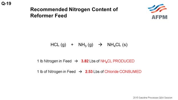
B) The ammonia (NH3) produced from the nitrogen in the feed will react with hydrogen chloride (HCL) present in the recycle gas to form ammonium chloride salt (NH4CL) in stoichiometric balance per the following equation.
HCL (g) + NH3 (g) à NH4CL (s)
From this equation, the following relationships are formed:
-
For every 1 lb (pound) of nitrogen in the feed, 3.82 lbs of ammonium chloride salt is PRODUCED.
-
For every 1 lb of nitrogen in the feed, 2.53 lbs of chloride is CONSUMED.
For a 30,000 BPD reformer:
Question 20: What are common causes for platinum agglomeration and the catalyst of continuously regenerated reforming units, and what are the common solutions to address these issues?
PATEL (Valero Energy Corporation)
The common causes for platinum agglomeration in CCR reforming units are the:
-
Low oxygen level in the chlorination zone;
-
Low temperature in the chlorination zone;
-
Low chloride injection into the chlorination zone;
-
Injection of off-specification (high water content) chloriding agent: The most common chloriding agent is perchloroethylene. The perchloroethylene should be dry Isomerization-grade perchloroethylene;
-
Wet air into the drying zone due to high level of moisture in the air supply or low temperature from the lower air heater;
-
Wet catalyst in a surge hopper maybe because of any coil leak;
-
Wet catalyst in the reduction zone due to cutting back the lower air rate; and
-
Lack of or insufficient drying zone residence time.
The common solutions for these issues are to fix them, if there are issues in the chlorination zone, because that is where the platinum will be dispersed in the chlorination zone after getting agglomerated in the burn zone.
-
Verify that the O2 content in the chlorination zone is more than 17%.
-
Maximize the use of lower air as much as possible.
-
Confirm that the gas flow rate to the chlorination zone is within the designed limit and also that the chlorination heater operating temperature is at design value.
-
Confirm the composition and lack of naphtha contamination of the chloriding agent. Check the chlorination injection fluoride and chloride content on the regen catalyst.
-
Confirm that there is no moisture breakthrough from the air dryers to the drying zone. Air has to be dry, less than 5 ppm of water, with a dew point of at least minus 85°F.
DUNHAM (UOP LLC, A Honeywell Company)
I am not a reforming expert, but I often travel with one. I have to listen to these discussions [laughter]. What Kiran said is all correct; it gets down to procedures. After you come out of the burn, you must go into the rejuvenation step. It is critical to do that properly, so it needs to be monitored. You have to have the controls right. If you do not disperse the platinum on the catalyst, it can snowball because that catalyst will come around again. So the key is to monitor this regeneration/rejuvenation step. If something changes, get it corrected right away.
KYLE BAILEY (Marathon Petroleum Corporation)
With respect to the air dryer package on the outlet or on the drying section, what is the practice for moisture content? Is it dew point analyzers, or do folks switch the dryer skid on a predetermined schedule to make sure there is dry air in the bottom of the regenerator?
KEADY (Technip USA)
It has been a very long time, but I have experience with an air dryer. It was not with a CCR, but I tried to do it. I worked with the operators to get a cycle based on the dryer dew point, but it did not work out well. So we all went back to a predetermined cycle for the air dryer.
Question 27: What impacts are you seeing in naphtha processing units from contaminants suspected to come from shale crudes (e.g. tramp amines, chlorides, fouling)? What are you doing to mitigate these impacts?
Dennis Haynes (NALCO Champion)
Tramp amines, chlorides, and fouling related to processing of Shale Crudes (or more specifically, Tight Oils) are issues that are of concern on the Crude Unit. I am not aware of issues specific to the gasoline pool and blending downstream of the crude unit. The strategies to deal with the tramp amines, or chlorides, focus on appropriate monitoring and minimization of the contaminants via desalting optimization or possibly caustic use; this includes tracking of salt points in the system. Fouling may be caused by various mechanisms related to Tight Oils, one of which is asphaltene destabilization due to incompatible blending, so fouling needs to be addressed after the mechanism for the specific situation is confirmed.
Greg Savage (NALCO Champion) Tight oil can contain tramp amines, which have resulted in crude unit tower, tower overoverhead temperature control as well as the use of caustic, desalter acidification, salt dispersants, and overhead chemical automation have reduced the risks of salt fouling in crude units.
Ka Lok (UOP) Several refiners have reported increased crude fouling when processing shale crudes, primarily in the crude column. head, and pump around fouling from salt formation. Operational controls such as desalter optimization, water wash, and
Question 28: What is your best practice for determining the maximum allowable temperature rise in hydrotreating beds? What solutions do you have for managing temperature rise?
Vern Mallett and Michael Leidy (UOP)
Operating philosophy regarding the maximum allowable temperature rise in hydrotreating beds from a design perspective is determined by several factors. Feed rate, composition in regards to feed reactivity and ratio of various feeds, length and diameter of each bed (L/D) designed catalyst type to be employed including graded bed type and main hydrotreating type, and estimated heat release. General design guidelines for maximum heat rise in a single hydrotreating catalyst bed are 28°C-42°C (50°F-75°F). However, there are single hydrotreating catalyst beds depending on feed composition (relative ratios of straight run and cracked stocks) where actual rise can exceed these guidelines and be in excess of 55-60°C (100°F-110°F). The decision to operate a single hydrotreating catalyst bed in these temperature ranges should be evaluated beforehand to determine available hydrogen gas rates, lower bed available hydrogen quench and hydrogen quench valve operation, multi-bed temperature profiles, and overall heat release in the reactor. Another consideration should be given to activity grading the first catalyst bed which, dependent upon feed composition, might reduce the overall bed temperature rise.
Question 29: What are your current best practices for protecting the charge heater from backflow?
Richard K. Hoehn (UOP)
Our design practice for a gas only heater uses a check valve at the outlet of the heater mainly to cut down on the chance of liquid flowing back into the heater during a compressor trip. For a combined feed heater (two phase) we do not use a check valve and instead concentrate on a robust and conservative heater design so that a tube rupture, which would be the cause of the backflow, is less likely to occur. Given the relative effectiveness of the check valve (it can stick in place), it is not considered a highly reliable safeguard for two phase operation.
Question 30: What is your minimum charge heater firing limit, especially when highly heat integrated or when processing cracked stocks? Do you have any hydroprocessing units run without firing the charge heater?
Gerhard Kraus (UOP)
The low firing limit is caused by burner instability. Heaters can be turned down by completely shutting off some burners; but there is also a firebox temperature component. Burner instability would be noticed visually – examples being flickering, irregular flame pattern plus increased CO emission. UOP designed heaters generally consider a targeted minimum firebox temperature of 1000°F for conventional Low NOx burners. The low firing limit in reality would depend on the actual burner used, firebox geometry, and fuel composition.
Michael Leidy (UOP)
Do you have any hydroprocessing units run without firing the charge heater? Hydroprocessing units do exist that can operate for periods of time without using the fired heater, however, not having or operating without a feed fired heater poses a process safety hazard since the ability to remove fuel gas from the feed heater (reduce firing) is a useful operating lever that facilitates the reduction of the inlet temperature to the reactor. Units designed and operated without continuously operating a feed fired heater require bypasses around many (if not all) of the feed effluent exchangers that should be opened to reduce heat to the inlet of the reactor in the event of a temperature excursion. In addition units (particularly hydrocracking) that have a high beta ratio (heat recovered in the feed versus the amount of heat added by the charge heater) may require bypasses of the feed effluent exchangers aswell.
Question 31: As more and more refiners consider installing zeolite catalyst in their hydrotreating units, what are your recommendations for a depressuring system?
Gabriela Gonzalez Lippke- and Michael Leid (UOP)
Though, many hydrotreating units operate at lower pressures than most hydrocracking units, loading zeolite catalysts poses a risk of temperature excursion which should be mitigated. Reactor thermometry, depressuring system capacity, and automating depressuring based on indication of excursion must be evaluated when cracking catalyst is loaded in a hydrotreating unit. Therefore, when zeolitic catalysts are used in hydrotreating units, in order to avoid temperature runaways and consequent damage in the eventof an emergency, the unit should be able to depressure in a relatively short period of time versus a traditional hydrotreating unit. Cracking reactions are not self-limiting as are hydrotreating reactions. Therefore, the reactants, liquid feed and hydrogen, are to be removed to stop the exothermic cracking reaction(s). To achieve the required rapid rate of reactant removal, the fastest and most efficient way is to de-pressure the unit.
The required depressuring rate depends on the unit volume and operating pressure. The lower both the volume and the pressure, the lower the required depressuring rate. UOP evaluates these factors when introducing cracking catalyst into hydrotreating units. There have been cases where the existing depressuring system satisfies the requirements for safe operation. Other cases involve small modifications to existing depressuring valve and / or restriction orifice. In the most extreme cases, the refinery flare system might need to be modified to accommodate the increased load in the event of depressuring from the hydrotreating / mild hydrocracking unit due to the required high rate of depressurization.
UOP recommendations for depressuring systems are automatic depressuring on high bed or skin temperature. The addition of this feature is highly recommended, but in unit revamp cases, the decision is typically made by the customer.
Question 32: How does catalyst activity, run length, H2 uptake, volume swell, reactor temperatures, price of the catalyst and product quality impact optimizing the business case for a catalyst selection? Compare a regen catalyst, moderate activity and next generation catalysts in a cheap H2 available market.
Mike Rogers (Criterion Catalyst and Technologies)
Refinery Process Engineers are often confronted with a complex and time-consuming process when it comes to choosing a catalyst for their hydrotreating units. The “Business Case” for a catalyst decision must take into account not only the catalyst costs and projected run lengths but also refinery margin and often a long list of other less obvious factors such as catalyst delivery and availability, technical support, and spent catalyst value to either cascade to other units or send to reclamation. A systematic approach starts by creating a decision matrix, listing all of the potential priorities that need to be taken into consideration, then for each discrete catalyst option, applying a score to each entry. The overall business decision is based on an aggregate of the scores, allowing consideration of many factors. The factors mentioned in the question focus on catalyst performance and cost:
1.Catalyst activity – This is often considered the most important attribute for a catalyst, since it typically has a direct impact on many of the other priorities. Higher catalyst activity means that the catalyst will do the same job at lower temperature, which in most cases is good. To estimate how the impact of catalyst activity on the business case, it is necessary to figure out how activity affects those other factors more directly tied to the refinery margin such as unit constraints or the catalyst cycle length. Sometimes catalyst activity can directly affect refinery margin by improving volume swell or improving a product property such as cetane or density.
2.Run Length – The run length between unit turnarounds (catalyst change outs) is most often defined by the catalyst, which starts life with a high activity enabling low temperatures. Over time, the activity declines and temperatures must be increased. The end of the catalyst cycle occurs when it is no longer possible to meet the production targets – either the product is not meeting specifications, or the unit throughput cannot be maintained. There is no “ideal” cycle length for all units. Each unit has its own particular circumstance that would define what the best catalyst cycle for it is. For example, many refineries are highly integrated, so that a shutdown of one unit will cause several others to stop or slow down. In those cases, catalyst cycles need to be synchronized to the turnaround schedules of all the other integrated units.
3.H2 Uptake – Assuming a case with cheap supply of H2 and a unit capable of supplying the required H2 makeup, economics typically support maximizing H2 uptake. The cost of cheap H2 is less than the value realized in the final product barrels from the associated volume swell in the hydrotreater.
4.Volume Swell – Volume swell has a direct impact on refinery margin, since increased “swell” results in more saleable product for the refinery. The HDS and HDN reactions in a hydrotreater generate some of the volume swell, but the majority comes from olefin and aromatic saturation reactions, which lower the product density. Criterion’s newest generation CENTERA catalysts are capable of significantly boosting volume swell compared to older generation catalysts. Criterion has a full line of NiMo catalysts (DN-3636 for ULSD, DN-3621 for HCPT and DN-3651 for FCCPT) designed to deliver significantly improved HDS, HDN and aromatic saturation activity to provide maximum benefit for refiners that target volume swell. Depending on unit capabilities, additional catalysts can be incorporated into the reactor to utilize Mild Hydrocracking or Ring Opening to further increase volume swell.
5.Reactor temperatures – Reactor temperatures are set by the operator to achieve the refiner’s processing objective for the unit. The catalyst activity directly affects the required operating temperature, and in that way, activity will have a direct impact on many operational factors. In many cases, catalyst deactivation will raise the temperature requirement over time, until an equipment limitation is reached. That condition will define the “end of cycle” for the catalyst. The reactor temperature also may also have an influence on the energy consumption in the unit. Energy will have a directly quantifiable cost which can be a factor in the business case.
6.Price of the Catalyst - The cost of catalyst replacement represents the easiest identifiable proportion of the overall unit operating cost of a hydrotreater. To justify the large expense of changing the catalyst, the cost should be balanced against the expected benefits that the catalyst load will bring and include any “recovered” value which might be gained at end of run, such as the value of the regenerated catalyst, or the reclaimed metals. The actual catalyst cost can be small compared to the potential benefits to be realized.
7.Product quality – Hydrotreaters are typically operated with a primary objective of achieving a certain product quality. Producing ULSD or Tier-3 gasoline requires tight sulfur control. Other quality objectives that should be considered when selecting a catalyst might include diesel cetane or product color. Newer generation catalysts have demonstrated significant gains on their ability to address a wider span of fuel quality issues.
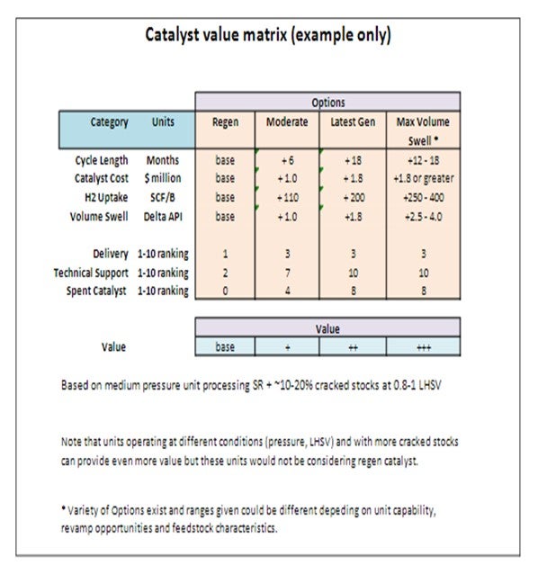
Catalyst Selection Matrix
A simplified example of the catalyst selection matrix for a ULSD unit is presented as follows. We used a typical medium pressure ULSD unit operating with a typical feedslate of SR and some (~10-20%) cracked stocks at 0.8-1.0 LHSV as our basis as this is the most likely scenario in which regen catalyst would be considered. Higher pressure units or units processing significant amounts of cracked stock should not even be considering using regen catalyst. For the max volume swell case, a variety of options can exist depending on the unit capabilities, revamp opportunities and feedstock characteristics and hence will have to be evaluated on a case-by-case basis.
As can be seen in the improved performance of latest generation and advanced catalysts system and as indicated by the potential value generated, there is significant value that can be realized by using latest generation catalysts. Units operating at different conditions (pressure, LHSV) and with more cracked stocks can provide even more value with utilization of latest generation catalysts and technologies. Each situation will have to be evaluated individually to determine the most economical solution. In addition to the value generated through volume gain, the other criteria (delivery, technical support and spent catalyst value) are also more attractive for the latest generation catalyst systems.