

Break
Session Start End
-
Question 64: What are the impacts on coker operation (yields, capacity, energy, coke quality) of excess VGO (1000F-) in the feed?
Jeff Lewellen (HollyFrontier)
Our El Dorado facility has transitioned from a 950o F HVGO/VTB cut point coker feed to a +1075 F while maintaining a fairly constant feed rate to the delayed coker unit. Our experience has seen coke and off-gas yield increase while HCGO yield decreases.
Our Conclusions:
• Yields – VGO range material is a relatively small contributor to coke yield in the unit. Between meter error and coke yield estimates, we have been unsuccessful in quantifying the exact yield impact.
• Capacity - Depending upon unit constraints, additional VGO occupies feed volume in the unit that could be used as VTB/residuum feed.
• Energy – The major impact is increased heater firing due to energy required to vaporize the excess VGO. This may also increase required drum temperatures to achieve equivalent VCM% results.
• Coke quality - Additional VGO may act similar to adding internal recycle to the unit. Although generally not aromatic, it could shift coke from shot to sponge coke. However, this is much more crude composition, drum velocity/pressure dependent.
Rajkumar Ghosh (Indian Oil Corporation)
Excess VGO in Coker feed is obviously not a desirable situation as it amounts to down gradation of straight run product. In one of our old refineries, we run a small Coker with long residue (RCO) as feed. Based on the experience there, the Impact of excess VGO in feed on Coker operation is explained as below:
a. Yield: The VGO part in the feed will have a free ride to the fractionator, thereby numerically reflecting higher distillate on Coker feed and consequent reduction in coke make. However, increase in coke drum vapor velocity will force higher pressure operation to prevent foam-over, leading to higher coke make from the residue part of the feed to the unit. The extent of increase in pressure will be dictated by the amount of VGO in feed.
b. Capacity: In the VR only case operation, if the feed to Coker is limited by Coke drum Capacities, then we certainly have a case for processing higher throughput in the excess VGO case, due to lower overall coke make. However, in such a case, Coke drum vapor velocity will also have to be cross checked and be maintained within the safe limit of 0.5 ft/sec. With lighter feed to Coker, the extent of vaporization in the heater tubes will be higher, leading to higher pressure drop across the heater. Heater duty will increase and may impose capacity limitations. Further, HCGO section flooding in the fractionator, HCGO product and pumparound circuit limitations may also become reasons for capacity bottleneck.
c. Energy: Excess VGO in feed will require higher heater duty. This may impose heater limitation with consequent lower COT. Lowering recycle under such a situation may help. However, it may result in higher HCGO CCR due to inadequate internal reflux in the wash zone. If HCGO circuit is not limiting, some of the heat can be recovered back into feed due to higher HCGO make.
d. Coke Quality: With the reduced wt% of asphaltenes, resins and metals in the feed, the coke quality will tend to improve. All the green coke produced with RCO feed is expected to be sponge coke with moderate VCM. Depending on the feed Sulfur content, the coke can be graded into Anode grade.
Eberhard Lucke (Commonwealth E&C)
Delayed Cokers are built to process residue, not gasoil. Excess VGO in the coker feed will only replace residue in the feed and will cause downgrading of almost all VGO to HCGO. HCGO yields will increase accordingly. The charge heater may benefit slightly from increased vaporization and lower fouling rates in the tubes. The coke may see an increase in VCM and may get a little softer, but this can be compensated by correct steam stripping.
Year
2011
Process
Question 65: What are the impacts on coker operation (yields, capacity, energy, coke quality) of FCC slurry oil in the feed?
Gary Gianzon (Marathon Petroleum Company)
When one of MPC’s refineries starts processing heavy Canadian resid, they add 5 to 10 volume percent of slurry oil in the feed to mitigate making shot coke. The slurry also helps meet anode grade specifications on metals and sulfur. Processing slurry backs out resid processing which can impact unit economics.
FCCU slurry has a similar boiling range to heavy coker gasoil, so a large amount of slurry flashes out of the drum and ends up in the heavy coker gasoil product. The coke yield from slurry feed is around 2 to 3 x Concarbon (depending on coker unit operation) which is significantly higher than vacuum resid at 1.3 to 1.6 x Concarbon. If a high percentage (over 10 percent) of slurry is processed in the coker unit, the slurry can cycle up between the coker and FCCU unit. The amount of recycle built-up is somewhat self-correcting depending on operations in the coker and FCC and whether the HCGO is processed in a FCCU Feed Hydroteater.
Rajkumar Ghosh (Indian Oil Corporation)
We are adding approx. 3–4 wt% FCC Slurry oil in Coker feed in one of our Coker and about 10 wt% in another. We also had undertaken a study in the Delayed Coker pilot plant in our R&D centre. Our experiences with processing of FCC slurry oil in the Coker feed, based on field and pilot plant results, are as under:
a) Yield: The impact of slurry oil in Coker feed depends upon the quality of the base feedstock, CLO/slurry oil and also the pressure / temperature of the coke drums. If FCC slurry oil boiling point distribution and the coke drum pressure / temperature are such that most of the slurry oil vaporizes out of the coke drum, yield of coke and gas reduces with increase in distillate yield.
In case of Fuel grade Coker, with CLO (with minimum overlap of LCO) below 10wt% in VR feed, coke yield by and large may be constant or may increase marginally depending on the relative quality of VR and CLO. Yields of total gas and liquid decrease marginally. Beyond 10 wt% (10-20 wt%) of CLO in VR feed, the coke yield may increase up to 4 wt%.
b) Capacity: The Coke produced with significant FCC slurry in Coker feed (>10 wt%) has a close-knit Coke matrix which ensures good porous structure to the Coke bed. This reduces the chances of hot spots and blowouts. But the negative impact of adding FCC slurry is pronounced where the coke drum is already limiting, as the porous structure results in lower coke bed bulk density and hence lesser vapor space in the Coke Drum. It may limit the Coker capacity.
c) Product quality: Tendency of formation of Shot coke significantly reduces with the addition of FCC slurry in the Coker feed, as it keeps asphaltenes in solution form. As per our experience at Panipat Coker, impact of slurry addition in the Coker feed is clearly visible on the Coke quality w.r.t. reduction in Shot coke formation. With increased FCC slurry in Coker feed, increase in Silica content in the green Coke would be a criterion to limit its wt% in the feed. This is significant for the Cokers producing Anode grade coke. Typical limit of Silica in Anode grade green Coke is 0.02 wt % max. Depending on the quality of the slurry oil and unit operating conditions, there may be a negative impact on the quality of the LCGO and HCGO. They will become more aromatics and heavier.
d) Energy: Slurry processing will require higher heater duty. High aromatic content in the slurry oil prevents the precipitation of Asphaltenes and thus increases the heater run length. Injection of slurry oil into the coke feed is limited by refinery configuration. In our Refineries with FCC and/or Hydrocracking units, we limit the slurry oil within 5 to 10 wt% on fresh feed to Coker. Increase in injection rate can lead to a massive recycle between the Coker and the FCC or will result in accelerated catalyst deactivation in the Hydrocracker unit.
Eberhard Lucke (Commonwealth E&C)
In general, FCC Slurry has a similar effect as VGO in terms that it replaces residue in the feed and increases mainly the HCGO yield. The difference in this case is that FCC Slurry is a highly aromatic stream and is often used as additional Coker feed (up to 15wt% max. recommended) to reduce heater fouling and to push coke morphology to sponge coke (for anode grade coke). The heavy aromatics in the FCC Slurry help keeping asphaltenes in solution a lot longer and promote coke formation by poly-condensation, therefore increasing sponge type coke content in the coke bed (preferred for low sulfur, anode grade coke production). On the downside, FCC Slurry will contain entrained catalyst fines and – if too high in concentration – may have a negative impact on fouling rates in the charge heater(s). The fine catalyst particles can deposit inside the heater tubes, act as seeds for coking and may promote deposits of heavy oil and coke fines from the oil film inside the tubes.
Year
2011
Process
Question 66: How does recycle affect time between coker furnace decokes/spalling?
Gary Gianzon (Marathon Petroleum Company)
Natural recycle helps to keep asphaltenes in solution; therefore, higher recycle tends to decrease furnace fouling assuming a constant furnace feedrate. Higher natural recycle reduces liquid volume yield and increases furnace firing which can impact unit economics. A recycle reduction test run conducted at one of MPC’s refineries shows increased heater fouling by 1 F/day when decreasing recycle from 20 to 10 percent. The impact of recycle on heater run length is feed/heater specific but increasing recycle should result in increasing heater run length at a constant furnace charge rate.
Jeff Lewellen (HollyFrontier)
Our experience indicates similar results to the primary answer. If internal recycle impacts unit charge rate, the optimal value becomes an economic decision weighing total throughput verses decoking frequency.
Eberhard Lucke (Commonwealth E&C)
Assuming all other parameters (coil outlet temperature, velocity steam rates, heater charge rate etc.) stay constant, increasing the recycle rate will add more heavy gasoil material to the feed stream. This increases vaporization in the tubes and helps lowering fouling rates which should allow to run longer between spalling/decoking. Reducing the recycle rate will have the opposite effect of reducing the vaporization rate and increasing the fouling rate in the heater.
Year
2011
Process
Question 67: With double-fired heaters, how long do you run between decokes (mechanical or steam-air)? What is your steam spalling interval? How much velocity steam do you maintain?
Rajkumar Ghosh (Indian Oil Corporation)
We have 8 operating Delayed Cokers across our Refineries. Of these, 2 have double fired heaters and others have conventional single fired heaters. With similar feed and Coker operating parameters, the double fired heaters are expected to have longer run length.
We get an average run length of ~12 months between decokes for one of our double fired heaters with on-line spalling of individual passes at an interval of 5-6 months. We process VR feed (CCR ~21 % wt; Sodium ~15 ppmw) with approx. 3%wt CLO and 12%-14 % recycle, and operating at 100% capacity level. We have also experienced a run length of about 2 years when the heater was operated with lower throughput and higher recycle (17-18 %). However, the coke deposit was very hard to remove by mechanical pigging and could only be removed by steam air decoking.
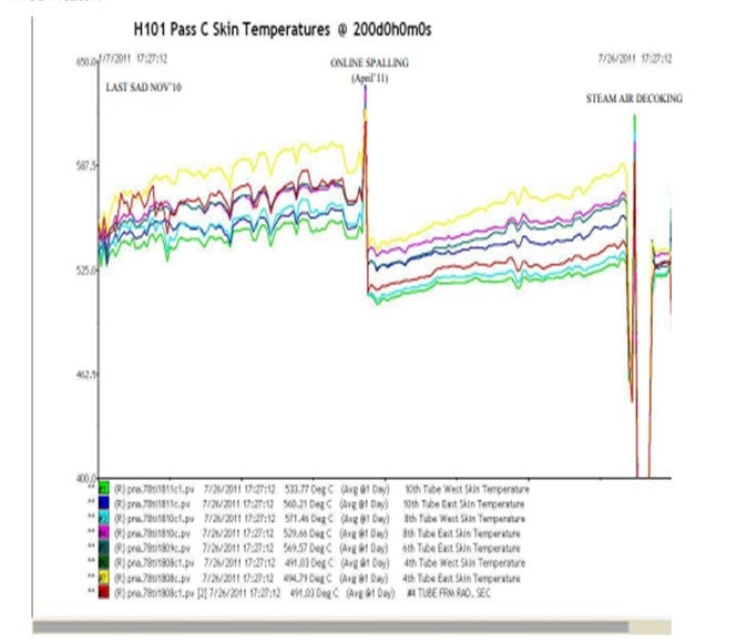
Tube metal temperature (TMT) and heater ΔP constitute the triggers for on-line spalling. In our case, with P-9 tube metallurgy, the trigger values are 614o C and 7 Kg/cm2 respectively. We always experience that the TMT limit triggers the requirement for on-line spalling, much before the ΔP occurrence. Between the SOR and EOR, the ΔP increase is limited to 1.5 Kg/cm2. One day average skin temperatures for over 200 days, is attached below for a typical pass in a Double Fired Heater.
It is important to mention that operational practices play a vital role in achieving longer run lengths of Coker Heaters and some of them are as under:
− Avoid interruptions which cause premature coking
− Feed quality, especially high Sodium and CCR aggravate coking
− Avoid any flame impingement on the heater tubes
− On-line monitoring of tube Skin Temperatures
− Keep the burner fuel pressure optimum
− Regular visual inspections
− Strict monitoring of Delta P across each pass
− Strict monitoring of velocity medium
Our Steam spalling interval is about 5-6 months. We undertake on-line spalling before the TMT reaches the threshold value of 614o C. In another upcoming Coker unit, skin temperature threshold value is 690o C and in this case steam spalling interval could be more than 6 months. Licenser does not recommend spall interval beyond 9 months as tube wall deposits become hardened and difficult to remove with subsequent spalling.
In all our 8 Cokers, we use Boiler Feed Water (BFW) as velocity medium, injected at the inlet of convection section, at the downstream of pass flow control valves. We maintain BFW quantity of 0.8-0.9 wt% on heater pass flow up to a maximum of 1% wt. At lower throughput, the velocity water is increased to approx. 1 wt%.
We have also used velocity steam in one of our Coker as a stop gap arrangement once for approx. 24 hrs when Boiler feed water was not available from upstream. No significant impact on delta P across the heater tubes or skin temperatures was observed after this operation.
Eberhard Lucke (Commonwealth E&C)
This question is lacking definition since it doesn’t define the severity of operation that the heater is required to perform in. I know of charge heaters in units with very high recycle ratios and very light residue feeds that can run up to 18-24 months between decoking. Other, more sever operations with ultra-low recycle and very heavy, aspaltenic residue feed show times between decoking that range between 3 months down to 6 weeks. This is independent from the type of decoking applied: pigging or steam-air decoking. These numbers are all based on no application of steam spalling. Steam spalling intervals may start at every 3-4 months, but will deteriorate with every application depending on how close the new SOR conditions are to the SOR conditions after a rigorous mechanical or thermal decoking. The minimum recommendation for velocity steam is 0.75 wt% of heater charge rate, but with heavier oil being processed and unit operations becoming more severe, values of 1 to 1.5 wt% of heater charge rate are becoming more typical.
Year
2011
Process
Question 68: What is a typical duration of online spalling of the coker furnace? What are the guidelines on maximum steam velocity during online spall?
Rajkumar Ghosh (Indian Oil Corporation)
Typical duration of online spalling is 16-24 hrs per pass of the heater.
Prima facie, the spalling operation is dovetailed with the coke drum cycle. We try to avoid continuing with the online spall during the changeover operation. This is to eliminate any chances of foam-over or coke carryover to fractionators. We start the spalling of a pass within 3- 4 hrs of drum switch and call it off prior to next switch. This gives us ~17-19 hrs in a 24 hr cycle. Change-over of feed to spalling media and reverse is not coincided with the drum switch to prevent causing any operational upsets in the coke drums.
But with refinery’s imperative of maximizing feed and with reduced coke drum cycles, we have continued with the spall operation even during the coke drum changeover without any significant negative experience. Due to the possibility of upsets during the change-over from feed to spalling media and vice a versa, precautionary addition of antifoam at the coking drums is recommended for 10-15 minutes before and after the change-over. This is to ensure that there is no carry-over from coke drums to the fractionator due to process upsets.
Typical flow rates and skin temperatures of a pass being spalled, trend attached below:
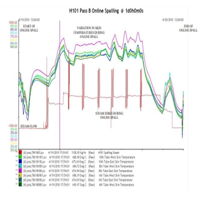
We use a combination of BFW and steam as spalling media, with BFW injection at convection inlet to cool convection section properly. Combined flue gas continues to be hot from other passes, which are operating as usual and BFW helps cooling the convection section of the pass being spalled. Steam is injected at the cross- over.
In our Coker, with 4” diameter heater tubes, we use about 4200 Kg/hr of spalling medium with max flow going up to 5000 Kg/hr during the intermittent jerks. The ratio of BFW to steam is about 65:35. The spalling media rate is dependent on coil size. Mass flux is of importance here. Typically, the value is 25-30 lb/sec/ft2 . However, it could be higher for a smaller duration. Aggressive spalling can lead to excessive erosion of the fittings such as the heater u-bends and the outlet header.
While increasing the spalling medium quantity during the course of spalling, we use coil inlet pressure of the coil being spalled as the guiding factor. We observe the coil inlet pressure; watch for any excessive increase in this pressure (2 kg/cm2 increase would be considered excessive) and adjust the spalling medium accordingly. If the pressure remains elevated for 15 to 20 minutes, we decrease the spalling medium to the initial rates used when starting the procedure.
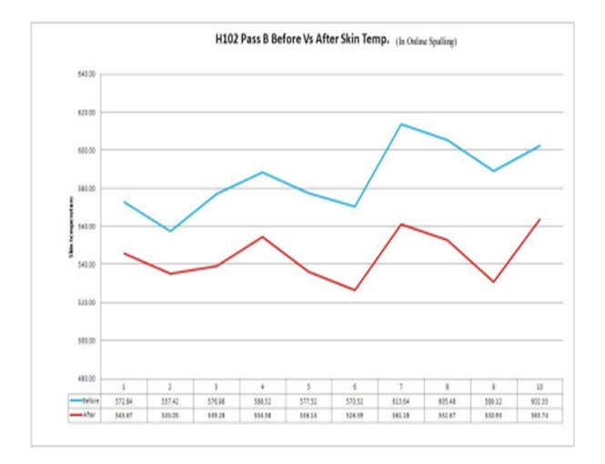
Below attached is a graph showing the gain in skin temperatures that we could achieve during online spall for a particular pass:
Year
2011
Process
Question 69: What are the effects of a poorly insulated coke drum? What is a good way to assess coke drum insulation effectiveness? How can the benefits of new insulation be estimated?
Jeff Lewellen (HollyFrontier)
Poor coke drum insulation impacts both the mechanical integrity and unit operation.
The mechanical integrity issues tend to be the easiest to quantify and address in our facility. The mechanical integrity impact of ineffective insulation includes:
• Uneven heating/cooling of drum wall causing elevated stress in these areas leading to shorter drum life.
• Under Insulation Corrosion (UIC) initiated by compromised insulation systems allowing rain and cutting water to infiltrate under the insulation.
Potential poor insulation impact to unit operation includes:
• Potential for lower drum outlet temperatures that impact foam stability, coke type, VCM, yields, internal recycle, etc.
• Potentially, slower drum warm-up step if significant loss of insulation performance. This may impact unit rate if the unit is cycle limited.
Our coke drum insulation maintenance begins with our mechanical integrity program. We rely upon visual inspection of equipment by operations and inspection personnel to initiate preventative/routine maintenance as necessary to maintain the integrity of the insulation system. Inspection by thermal imaging camera has also provided to be useful in locating problem areas.
Process indicators can be more difficult to monitor in our facility due to varied feed slate that impacts the coke formation properties in the drum. This makes monitoring the drum inlet/outlet temperature unreliable to predict heat loss. Monitoring coke cutting logs for unusual coke qualities and problems can be insightful to detect several issues including insulation problems. Notations that describe difficulty to clean walls in certain drum elevations or unusual changes in coke types with elevation may indicate problem areas in the drums.
Rajkumar Ghosh (Indian Oil Corporation)
A poorly insulated coke drum results in heat losses to the atmosphere, reducing the available heat for cracking reactions. The effects of poorly insulated Coke Drums as per our experience are as follows:
a. VCM or the Volatile Combustible Matter in the Green Coke tends to be on the higher side with a poorly insulated Coke Drum as compared to the one which is properly insulated. Coke Drum outlet temperature (before quench) is a key parameter to monitor the VCM content of the Coke. We have experience of a Coke Drum having damaged insulation. The change in Coke Drum outlet temperature (with the same inlet temperature) before and after the complete replacement of insulation is in the range of 3-4°C.
b. Condensation of heavy ends on the relatively cooler Coke drum walls results in higher Coke yields and loss of corresponding liquid yields, as this correspondingly increases the internal recycle within the drum. The Coke produced would be soft because of the higher internal reflux and higher VCM.
c. Poor insulation may also lead to uneven cooling and accelerated ‘banana effect’ of the coke drum.
Good ways to assess Coke Drum insulation effectiveness are:
a. The drop in temperature across the drum. The temperature drop of the Coke Drum inlet and the vapor outlet from the top of the drum should be around 40-45o C. If the drop is more than this figure, then the Coke drum insulation needs reinforcement.
b. Monitoring the quench flow that is being injected into the vapor line for the same throughput can indicate the effectiveness of insulation. The quench flow comparison over a period of time can help ascertaining the condition/ effectiveness of the insulation.
c. Monitoring of the skin temperatures of the coke drum can also give an idea about the condition of the coke drum insulation. A lower indication of the skin temperature than normal can indicate poor insulation.
d. Above all, visual inspection gives a good insight to the state of health of the insulation. The benefits of new insulation are derived from lower coke VCM, which can be directly translated into improvement in liquid yield.
Year
2011
Process
Question 70: How do you monitor coke drum cutting water for fines content (test methods, frequency, time in cycle) and what is your trigger level for action to reduce fines content?
Rajkumar Ghosh (Indian Oil Corporation)
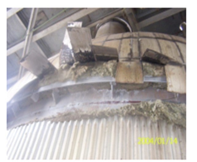
There are different methods to separate the fines in cutting water. In our latest Cokers, we have hydrocyclones, provided at the discharge of the reuse water pumps. The older cokers deploy clarifier.
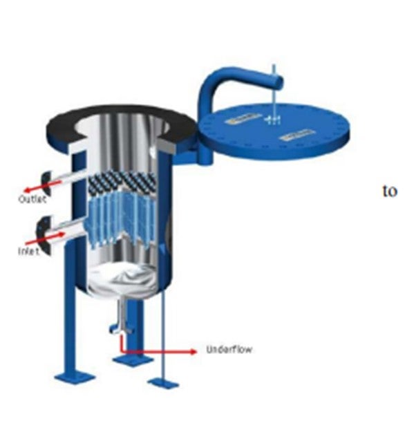
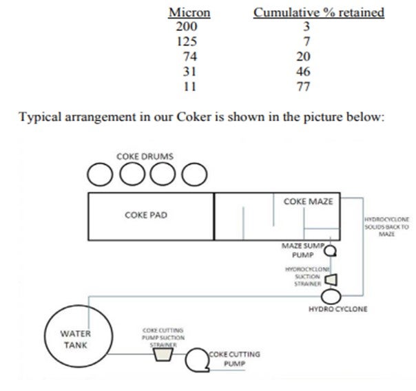
The water reuse system consists of a settling maze and a vertical pump to pump the water back to the coke cutting water tank after separating the coke fines by passing it through hydrocyclone. The settling maze consists of 4 partitioned chambers, with water cascading from one chamber to the other, thereby effecting coke fines settling at stages. The coke cutting pumps typically take their suction from the middle of the water tank so that carried over coke fines settle at the tanks bottom. The hydrocyclone consists of 42 nos. of individual ceramic body cyclones, bundled in a cylindrical shell. It is designed to remove 80% of influent coke fines. The coke fines separated as hydrocyclone underflow, move back into the settling maze, while the clear water comes out as hydrocyclone overflow. In our case, the hydrocyclone is designed for the following influent conditions:
− Flow rate: 250 m3/hr
− Solids: 0.04-3.0 wt%
− Particle size distribution
The monitoring of water quality is necessary to prevent damages in the coke cutting nozzle and coke cutting pump impeller. We adopt the following monitoring mechanism for ensuring the coke cutting water quality:
a. The coke cutting pump has a suction basket strainer of 80 mesh size. The strainer is taken up for cleaning when ΔP across the strainer becomes 0.25 Kg/cm2. Under normal situations, the strainer is required to be cleaned once a week. Underperformance of hydrocyclone is reflected in frequent clean-up requirement of the strainer. In such cases, the hydrocyclone is opened up and the clogged cyclones are cleaned. Typically, the hydrocyclone is cleaned after every 4 months.
b. Based on our experience of occasional clogging of hydrocyclone due to excessive fines generation, we had installed a strainer at the upstream of hydrocyclone. The frequency of strainer cleaning gives us a fair indication of the extent of fines generation in the coke cutting process and thereby corrective action in the process parameters.
c. The coke fines get separated at stages in successive chambers of the maze. During the end of the cutting cycle, we collect water sample from the last chamber of the maze and allow settling for a while. By visual comparison with the earlier samples, we try to ascertain whether excess fines are getting generated in the process. Coke fines are removed from the maze by the bridge crane. Generally, once a day cleanup is adequate.
d. The residual coke fines which pass through the hydrocyclone tend to settle in the water tank. The tank bottoms are drained into the settling maze after each cutting cycle to remove the fines building up at the tank bottom.
e. Despite the actions as above, if the coke cutting pump suction strainer requires frequent cleaning, the water tank content is partially replaced with fresh water.
f. And finally, settling maze and the water tank are completely taken up for cleaning during unit turnarounds.
Although the water sample from the coke cutting pump suction can be monitored for coke fines content by periodical sampling and its’ lab analysis by filtration method, in practice it is quite infrequent in the field. However, the safeguards and practices, as explained above have been found to be effective and we have not experienced any deterioration in the coke cutting pump and cutting tool in the last 5 years operation of this particular refinery.
Year
2011
Process