
General Session: HON (45 Tech/45 Fenceline): Updates on EPA’s Proposed Revisions to Several Chemical Industry Air Rules | Progression of Fenceline Monitoring: More Sources, More Methods
Part 1: Technical
Presentation 1:
Updates on EPA’s Proposed Revisions to Several Chemical Industry Air Rules – Provide background on EPA’s proposed and finalized changes to several chemical sector rules including the consolidated reconsideration of RSR, MON, EMACT, and OLD, and the recently proposed changes to the HON and NSPS rules. This introduction will summarize the changes and will discuss EPA’s rationalization of the revisions, including those for ethylene oxide. Major industry and non-governmental organization comments that may impact final rules will also be covered.
Presentation 2:
Strategies to Comply with the Earliest New HON Requirements at Petrochemical Plants and Refineries This presentation offers a “nuts & bolts” outline for implementing the proposed new HON provisions. “In ethylene oxide service” determinations and requirements involving non-environmental staff and long lead times are examples of tasks needing early attention. The presentation will also include a high-level introduction to fenceline monitoring pilot studies as part of the overall compliance strategy.
Part 2: Fenceline Monitoring
Progression of Fenceline Monitoring: More Sources, More Methods – This presentation will cover the current state of affairs for refinery fenceline monitoring (FLM): when it started, trend in sample results, number of facilities currently above the action level (on annual basis), investigation methods, and general lessons learned. The HON FLM program requirements and how the HON FLM program differs from the refinery FLM program will be discussed. The details of the two HON monitoring methods, passive tubes and evacuated canisters, will be provided and compared/contrasted side-by-side, to illustrate the complexity and challenges of this proposed monitoring program. A summary of the industry group concerns regarding the HON FLM program expressed in the initial proposed rule comments and subsequent interactions with the agency, up until the conference, will also be provided.
Speakers: Amy Marshall, Gary Daves, Patricia Sorensen, Derek Reese
Moderator: Mary Bachynsky
Session Start End
-
Registration
Session Start End
-
General Session
Speakers
Session Start End
-
Question 7: Are there any standard sampling and analytical methods that can be used in the refinery labs to accurately determine the silicon content in the feed to the coker naphtha hydrotreater?
Tim Lewer (Shell)
The issue is how to accurately determine the silicon content. Standard Inductively Coupled Plasma (ICP) techniques will give a result that is equal to or greater than the true amount of silicon present depending on if the silicon is in a volatile form (low molecular weight silicones). So, ICP can be used to screen samples and ensure silicon levels are below a desired limit. However, if silicon is detected, it could be a false high number due to nebulizer enhancement effects. Alternatively, a new ASTM method using Monochromatic Wavelength Dispersive X-ray technology may be able to accurately measure even volatile silicon species, but the instrumentation is new to the market and does not have a long track record to verify its applicability. A direct injection nebulizer ICP system will accurately measure silicon including volatile forms but is typically too customized of a system for application in a refinery setting.
Be aware of cross contamination when taking samples for silicon analysis. Some plants have seen false high silicon lab results due to silicone grease used for lubrication or certain silicates used in the manufacture of glass bottles. There has also been cross contamination from puncturing certain silicone sample bottle lids during the sample collection process.
Some plants have established a sample station that takes a small sample every 15 minutes into a compositor that is used for a weekly composite analysis. This method doesn't improve sampling speed but does reduce the frequency and improves accuracy.
Kaspar Vogt (Albemarle)
Inductively Coupled Plasma (ICP) is the technique most used. ASTM D-5708, which is intended for determination of nickel and vanadium in crudes and residual oils, has become the de-facto standard for preparing hydrocarbon samples for elemental analysis by ICP. This is probably the most appropriate method for analyzing the silicon derived from the anti-foam agents added to the feedstock, as opposed to the silicon you might find associated with FCC fines suspended in the sample. The detection limit is around 0.5 ppm. The standard deviation is +/- 0.25 ppm.
During operation, silicon addition is minimized in the coker cycle however the refinery does not want to experience a foam over. Understanding the amount of silicon fed to the hydrotreater is complicated as the anti-foaming agent dosage varies during the coker cycle. More sophisticated continuous sampling systems are available and are capable of sampling hourly or periodically and can create a one or multi coker cycle composite sample.
A spot sample value should not be used to predict the life expectancy of the hydrotreating catalyst; the composite sample will be more useful. We recommend to measure the silicon concentration present on the spent catalyst after the cycle is complete and back calculate the average concentration of silicon in the feed. A properly designed guard catalyst system can significantly lengthen the cycle by catching silicon and other poisons before they reach the main bed high activity catalyst.
Martin Gonzalez (BP)
Spot samples of coker naphtha taken for measuring silicon content can have high variability. To obtain a reliable average, you can use a sampling system that accumulates volume over several hours. X-ray fluorescence technology has developed to where a limit of detection of 0.5 ppm silicon is achievable. Gas Chromatography-Mass Spectroscopy (GC-MS) is also useful to quantify the specific siloxanes formed from decomposition of coker anti-foam.
Gerianne D’Angelo (ART)
Accurately measuring silicon in naphtha streams can be done but it takes a bit of work to get a representative sample of the naphtha. The silicon in the coker naphtha depends on the type and amount of antifoam chemical at the delayer coker unit. Delayed cokers have cycles ranging anywhere between 8 – 24 hours. The coker unit is continually producing a coker naphtha stream during these cycles which is typically being sent from the fractionator straight into the naphtha hydrotreater feed drum. The antifoam chemical is usually not added for the entire coker cycle. This means that the silicon in the naphtha stream will vary with the timing of the coker cycle. In order to get a representative amount of silicon in the coker naphtha stream a composite should be made of hourly samples mixed together for the time of the cycle. For example, for an eight hour cycle eight samples would be mixed and the composite sample analyzed for silicon. To measure the silicon an ICP-MS (Inductively Coupled Plasma Mass Spectrometry) instrument can be used. This instrument/method can measure very low metal concentrations.
Year
2011
Process
Question 8: In order to minimize fouling of the hydrotreater reactor feed/effluent exchangers, how important is it to have hydrogen gas in the feed side of the exchanger? Is there a minimum gas flow to see the benefit? Does it matter if it is recycling gas or makeup hydrogen?
Shankar Vaidyanathan (Flour)
Pre-mixing hydrogen with feed ahead of the feed/effluent exchangers improves the velocity and increases the shear stresses. This directionally reduces the fouling tendency; as well as, lowering the film thickness and dependent tube wall temperature in the heat exchanger and the charge heater. Hydrogen also offers the physical benefit of sweeping and helps avoid settling particles.
Design criteria such as flow regime, turbulence, design pressure drop, and velocity are specified in order to minimize fouling. The unit capacity and overall heat balance are often factors in selecting two phase or single phase exchanger. Two phase heat transfer coefficient is better than single phase design hence there is a credit in surface area. In order to fully realize this benefit, a large hydrogen quantity, sometimes up to the unit’s treat gas demand, may have to be sent to the front of the exchanger for pre-mixing with feed oil. A caveat while considering the benefits of pre-mixed two phase designs is not to compare the heat exchanger performance to poorly designed liquid only designs. A high fouling factor originally specified may have inadvertently led to a self-fulfilling prophecy of higher fouling in service. In recent years, even liquid only heat exchangers are increasingly designed with high shear stresses to mitigate fouling.
Process control and metallurgy issues need to be worked out for existing liquid only designs before considering pre-mixing gas. The mixing point should be at an appropriate distance ahead of the feed/effluent exchanger to allow mixing time. A minimum soaker hydrogen addition, just enough to keep the dissolved hydrogen in liquid phase such that the flow could be metered and balanced at heater inlet may be considered. The soaker hydrogen could be in the 50-200 SCFB range depending on the unit pressure, heat balance and hydrogen solubility which is temperature dependent. There is some experience in the industry that shows soaker hydrogen minimizes fouling especially with cracked stocks. Bypassing a portion of the treat gas around the preheat system may also be a preferred way to hydraulically debottleneck existing plants. We do not discriminate between recycle gas and makeup hydrogen since any partial pressure credit and solubility differences for using pure makeup hydrogen are relatively minor.
Martin Gonzalez (BP)
Feed/effluent exchanger fouling in hydrotreaters is often the result of oxygen-induced polymerization of olefins. Chain initiation begins with a free-radical mechanism involving molecular oxygen, disulfides, or pyrrolic nitrogen species. In many cases, it appears that mercaptans can polymerize and olefins content needs to be very high. From our experimentation, we have found that hydrogen may not react chemically to stop such fouling at the relatively mild conditions where such polymerization occurs. The exception may be where diolefins are present in high concentrations such as in hydrotreating of light coker naphtha. However, injection of hydrogen into preheat exchangers is effective for increasing superficial velocity, which helps fluidize particles and flush them out of the exchanger. When feed is on the tube side, the necessary fluidization velocity can be calculated based on particle size distribution analysis. A volume of hydrogen equivalent to make up gas flow rate is likely to be sufficient. Recycle gas or combined treat gas may be used.
Minh Dimas (CITGO) The feed side of our Naphtha Hydrotreater Feed/Effluent exchangers has plenty of H2 but always has fouling issue. We have tried anti-foulant with limited success. In our ULSD unit, the Feed Preheat exchanger (feed/product exchanger) has experienced severe and rapid fouling. Lab analyses confirmed two fouling mechanisms: radical-polymerization and oxygenate-polymerization. The feed side does not have H2. We are going to start using anti-foulant while working on long-term mitigation.
Year
2011
Process
Question 9: What has been your experience with antimony and phosphorous poisoning on hydrotreating catalyst performance? What is the maximum level?
Kaspar Vogt (Albemarle) Antimony (Sb)
The effects of antimony in oil on hydrotreating catalyst have not been directly studied, but we can infer the likely impacts of antimony from a variety of information sources and past experiences.
As background, contaminant metals such as nickel can deposit on the FCC catalyst. This will result in increased dry gas (H2 in particular) and delta coke. Depending on the unit constraints this can lead to lower FCC conversion and lower feed rate. Many refiners use antimony in the FCC riser to passivate the detrimental effects of nickel. Antimony will cover the nickel enriched catalyst surface. Side effects are that the Sb will also cover the CO and NOx promoter metals and make these additives less effective.
Excess antimony mainly accumulates in the FCC slurry. However, antimony can be present in the heavier FCC products which are hydrotreated downstream. If the antimony enriched FCC catalyst fines are entrained into the hydrotreater, they can deposit in the catalyst interstices. This will impact bed pressure drop but not catalyst activity. The bed pressure drop build up can be managed by a guard bed catalyst system of sized and shaped catalysts to increase the void fraction and create more particulates capacity.
By analogy with the FCC experience, we would expect antimony in oil to preferentially coat nickel and cobalt promoter metals on the NiMo and CoMo catalysts. Ultimately, this would completely poison the catalyst. During the buildup of coating/poisoning, the activity will likely see a shift towards direct desulfurization (DDS) vs. indirect/aromatic saturation, thus the hydrogenation-to-hydrogenolysis ratio will change. A given concentration of Sb on catalyst would be expected to have a more severe effect on the catalyst performance in high severity HDS/HDN operations like ULSD and hydrocracker pretreat (HC-PT) service than in lower severity hydroprocessing applications such as NHT and LSD.
We seldom, if ever, detect antimony in the interior of spent hydrotreating catalysts where it would be expected to impact activity.
Furthermore, given its position in the periodic table, we would expect that Sb attacks the catalyst's active (NiMo and CoMo) sites, and that it would be a relatively severe poison, similar to arsenic (As), sodium (Na) and lead (Pb). Therefore, we would expect ≤1.0 wt% Sb would reduce HDN/HDS relative volumetric activity (RVA) by approximately 50% in non-severe applications, and that even lower Sb concentrations could severely reduce catalyst activity for high severity operations like ULSD and HC-PT.
Phosphorous (P)
Phosphorous (P) can come into the hydrotreater feed from:
- crudes
- drilling fluids
- phosphated ZSM
- phosphorous-based corrosion inhibitors and flow improvers
- phosphorous from solid phosphoric acid catalyst
-biofeeds
In catalyst manufacturing, phosphorous added on hydrotreating catalyst acts as a promoter and provides additional acidity to enhance HDN, hydrogenation and cracking reactions. Phosphorous also improves metals dispersion on the catalyst surface.
In one instance, we saw that 3 wt% of phosphorus on the catalyst terminated all the exotherm in bed, although other poisons where also present. Organic phosphorous can penetrate into catalyst pores. In general, our understanding is that the poisoning was similar to sodium where ~1.0 wt% concentration halves the catalyst activity.
In a separate instance, we found SiP coming from a solid phosphoric acid catalyst, used in certain FCC gasoline desulfurization processes with some iron deposited at the external surface of the catalyst extrudate. Some phosphorous and silicon also penetrated the catalyst pores. However after the first 0.1 mm, no contaminant phosphorous and silicon were found on a main bed CoMo catalyst. In this case, a layer of P-Si-Fe had deposited at the pore mouth and restricted the diffusion into the catalyst.
Photos of the outer surface including chemical composition are shown below. They show that Alumina, Molybdenum and Cobalt are homogeneously distributed within the catalyst particle, while phosphorous, silica and iron are located at the outer surface of the particle.
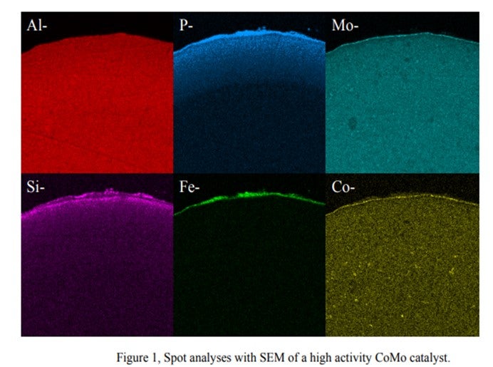
We observed that the Si & P from this process behaves totally differently from Si from anti-foaming agents. There are Si-P particles which cannot penetrate the internal pores of the catalyst and are deposited on the catalyst outer surface. The accumulation of these particles cannot be prevented. Therefore, sooner or later, bridges from particle to particle are formed, thus causing pressure drop buildup.
The bottom line is that the quantitative effects of phosphorous on hydroprocessing catalyst performance and the maximum allowable levels are highly dependent on the source and form of the phosphorous compound. It is also dependent on catalyst properties and the process application.
Martin Gonzalez (BP)
Phosphorus can sometimes be found in crude as alkyl phosphates added to passivate metals or protect against naphthenic acid corrosion. Phosphorus esters in crude may originate from waste oils, or from additives injected into wells to improve recovery. Some of the phosphorus may be in a form that volatilizes into distillate fractions bound for hydrotreaters. We have encountered some Canadian crudes containing phosphorus originating from fracturing fluids used in production. Phosphorus content in light sweet crudes seems to be declining, but it may be becoming more prominent in heavy crudes. There have been reports in the industry of ULSD units suffering catalyst deactivation as result of phosphorus from these crudes. From our experience, at 1 wt% on catalyst, it is reasonable to expect a 15-30% activity loss.
Charles Olsen (ART)
Phosphorous (P) contamination in oil has been traced to frac fluids that are often used in crudes from the Western Canadian Sedimentary Basin. The source is diphosphate esters which are soluble in the crude oil. Refineries that run large percentages of light Western Canadian crude have reported crude column and crude furnace fouling for many years. Improvements made to crude columns to minimize fouling have transitioned the depositing of phosphorous to the downstream hydrotreaters.
Other sources of phosphorous include gasoline slop tanks, imported feeds and lube oil wastes. If phosphorous does manage to make its way into the hydrotreater it will poison the active sites of the catalyst causing a loss in activity. A level of 1 wt% of phosphorous on the catalyst results in roughly 10°F loss in activity. ART recommends that a feed content of < 0.5 wppm be maintained whenever possible as well as the use of feed filters to assist in trapping of phosphorous sediment.
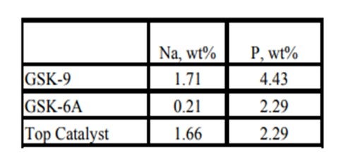
Historically, phosphorous contamination has not been very common, but with the increasing use of opportunity crudes it is being observed more frequently. A recent example is summarized in the table below shows the results of some spent catalyst analysis from a diesel unit. This unit experienced extremely rapid catalyst deactivation shortly after start up. It was so severe that within several months the unit required an unplanned turnaround and fresh catalyst was installed. The spent catalyst analysis indicates the catalysts were exposed to high levels of several poisons including sodium and phosphorous. The contaminants penetrated well into the catalyst bed. The level of contaminants indicates the catalyst in the top half of the bed had lost over 60°F of activity.
Year
2011
Process
Question 10: When replacing a noble metal catalyst with a base metal catalyst in a two-stage hydrocracking unit configuration, how can you be certain that under a low sulfur, low hydrogen sulfide environment, the second stage catalyst will remain sulfided?
Kaspar Vogt (Albemarle)
A base metal sulfide catalyst will always have less, or hydrogenation compared to a noble metal catalyst. However, in certain situations where deep hydrogenation is not needed, the base metal sulfide catalyst can provide adequate hydrogenation activity. Operation with a base metal catalyst will be between 10 to 20o F higher than a noble metal catalyst, and this will shift the yield towards more thermally cracked lighter products.
Due to the presence of platinum on the noble metal catalyst significant fill cost savings are achieved by loading base metal catalysts.
It would not be recommended to operate a base metal catalyst in a completely sweet service without the presence of H2S. The catalyst risks reduction of the metal sulfides, which will impact the activity and can permanently damage the catalyst.
Effective ways to get around the sulfur stripping of the base metal catalyst in an H2S free environment include spiking by DMDS injection, slipping of some sour gas from the 1st stage over to the 2nd stage, turning off the amine wash, and/or raising the hydrocarbon organic sulfur slip. H2S in the second stage recycle gas is in the range of 15 to 40 ppm to keep the catalyst sulfided.
For a standalone second stage reactor, another issue is corrosion. Since a typical sweet second stage does not have wash water injection, it is important to be careful of metallurgy, especially on the second stage air effluent coolers.
Year
2011
Process
Lauren Grimm
US Chemical Safety Board