Lunch in Exhibit Hall
The vendor exhibition offers attendees an opportunity to learn about the latest products and services available to the industry.
Session Start End
-

Question 74: For a unit targeting low vapor pressure gasoline, which variables have the greatest impact on isopentane production?
REYNOLDS (Phillips 66)
Phillips 66 has not done very much research towards iC5, specifically. We did review some base data and looked for some correlations with what impacts the iC5 production, and we did not find too many that are strongly correlated.
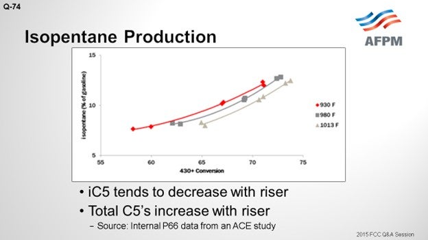
The riser does have an impact. On the Y axis, this plot shows the isopentane as a percentage of the gasoline; a 430°F+ conversion is shown on the X axis. There are three curves representing three different riser temperatures. There is a very wide range in these three risers: from 930 to 1013°F; but at constant conversion, the iC5 decreases with riser outlet temperature by about 1.5 wt% across that really wide range of riser temperatures. Across the conversion, there is a fairly significant change. So, as you crack more material into gasoline, the fraction of gasoline that is comprised of the total C5s will go up.
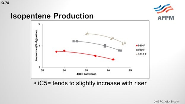
I included isopentene. The C5 olefins will be present along with the iC5s. They have a similar RVP (Reid vapor pressure). As opposed to iC5, C5 olefins increase with increased riser with a similar magnitude of change. So essentially, you are trading barrels of iC5 for C5 olefins, which has a negligible effect on RVP.
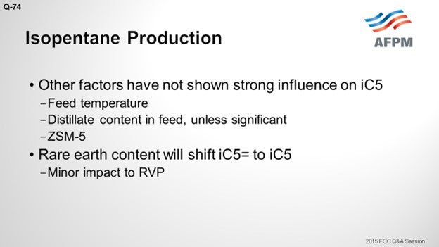
Other parameters we have reviewed which really do not seem to influence iC5 production are feed temperature and distillate content in the feed. You must have a significant change in distillate content; for example, a 40% change of your feed distillate will make about a 1% iC5 change. Unexpectedly, we did not see too much of a correlation with ZSM-5. You would think that if you crack the C6/C7 range of gasoline into LPG, you will have a concentrating effect; but we did not see that. Bart probably will disagree with me. Rare earth content will shift your olefins to your iC5 via hydrogen transfer reactions; but again, it will not have a huge impact on the RVP.
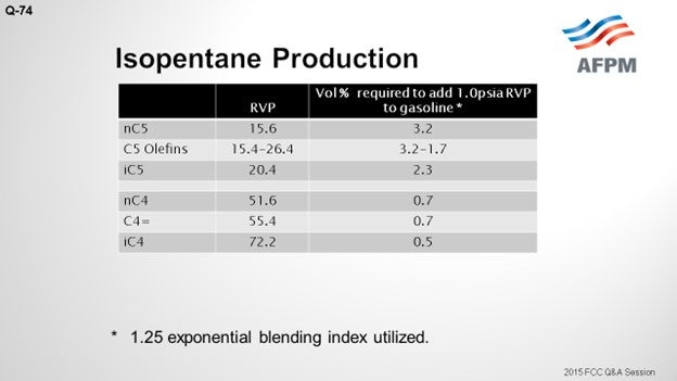
This table shows some of the RVPs for the C4- and C5-range materials. I included a column that indicates the volume percent required to add one psia (pounds per square inch absolute) of RVP to gasoline. You can see that there is a significantly larger impact from the butanes. So, when comparing normal butane to iC5, you can see that it has about four times the impact.
In conclusion, I think a facility must have an extremely high value of RVP barrels to warrant riser or catalyst formulation to make a negligible impact on iC5. I think your first priority is to try to get as much of the C4s out of your gasoline as you can. If you really do have C5s that are impacting your blending pool RVP, you should look at fractionating them out of gasoline into your C4 streams.
DE GRAAF (Johnson Matthey Process Technologies)
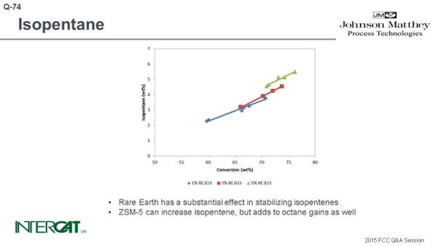
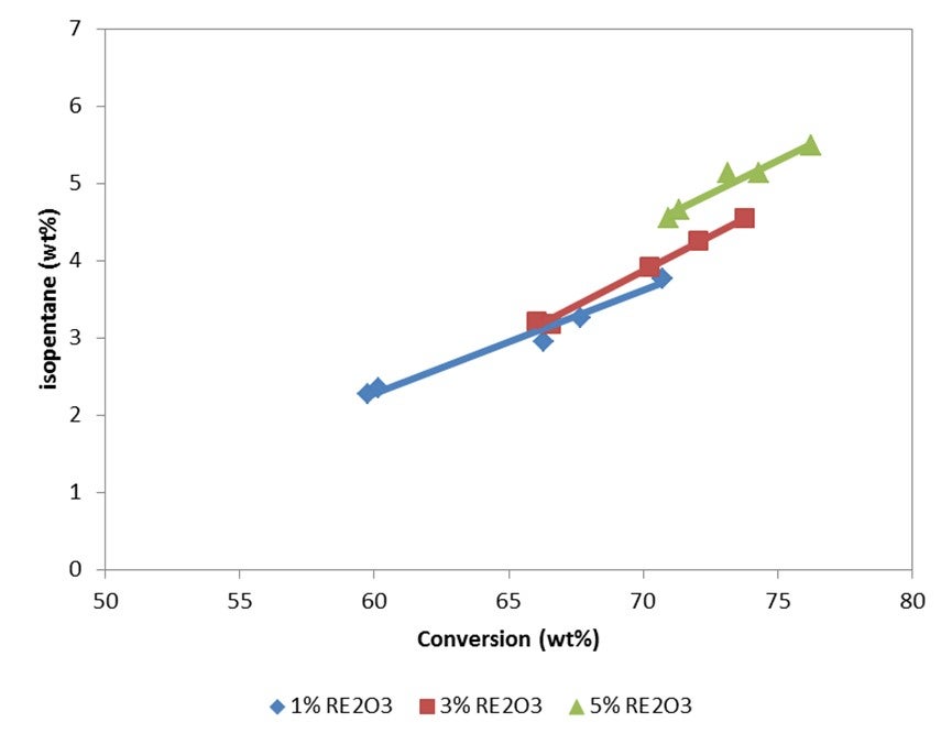
Isopentane is one of the lightest components in gasoline, and typically everything that increases conversion will increase isopentane. The rarer earth you have, the more hydrogen transfer of your catalyst, the more isopentane you will create. So, if you go for a higher riser outlet temperature, you will shift the equilibrium between isopentane and isopentene. A higher rise will give you more isopentane. Use of ZSM-5 additives can increase isopentanes because isopentenes can be transformed into isopentanes by hydrogen transfer. However, the effect of conversion is the most important factor affecting the amount of isopentane formed.
KENNETH BRYDEN (Grace Catalysts Technologies)
While the question asks specifically about isopentane production, other C5 hydrocarbons also have significant vapor pressure. Isopentane has a Reid Vapor Pressure (RVP) of 20 psi (pounds per square inch); n-pentane has an RVP of 16 psi; and, the C5 olefins have RVPs between 14 and 26 psi9. For refineries desiring to minimize RVP, it is also important to minimize the quantity of C4s in the gasoline pool since C4s have even higher vapor pressures than C5s.
Isopentane is mainly produced in the FCC unit via two pathways. The first pathway is cracking where isopentane is formed when a larger paraffin molecule cracks via β-scission to form isopentane and an olefin. The second main pathway for isopentane production involves hydrogen transfer reactions that transform C5 olefins into isopentane. Hydrogen transfer is a disproportionation reaction where hydrogen is moved between molecules. Isopentane production is influenced by operating conditions, feedstock properties, and the properties of the catalyst used. Factors that influence hydrogen transfer have the greatest impact on isopentane production.
As conversion is increased (by either increasing reactor temperature or by increasing catalyst-to-oil ratio), the quantity of isopentane (and gasoline) increases. At constant conversion, increasing reactor temperature will reduce the amount of isopentane produced, as hydrogen transfer tends to be favored at lower reactor temperatures. And since hydrogen transfer is a bimolecular reaction, decreasing reactor pressure lowers hydrogen transfer and will lower the amount of isopentane produced.
As a feedstock becomes more naphthenic, the production of isopentane tends to increase. This is because naphthenes are good hydrogen donors and react with gasoline range olefins to make aromatics and gasoline range paraffins10.
FCC catalyst can affect the rate of isopentane production through hydrogen transfer activity. As hydrogen transfer increases, more paraffins are formed and isopentane production increases. Figure 1(a) presents isopentane yields on a fresh feed basis at 72% conversion for a series of catalysts with a range of unit cell sizes (UCS) between 24.22 and 24.44 Å. To maintain similar activity, the higher UCS catalysts were formulated to a lower zeolite level. Figure 1(b) presents isopentane concentration in gasoline as a function of UCS for the same catalysts. As expected, isopentane yield and concentration in gasoline increase with UCS since the acid site density and the relative rate of hydrogen transfer to cracking is increasing.
The use of ZSM-5 based additives does not significantly change the yield of isopentane on a fresh feed basis, but it will increase the relative concentration of isopentane in the gasoline. As the higher olefins in gasoline are cracked by the ZSM-5 to propylene and butylene, the gasoline becomes enriched in isopentane. Figure 2(a) presents isopentane yield on a fresh feed basis for a series of ZSM-5 additive levels. While there is a slight increase in isopentane yield with ZSM-5 additive level, the isopentane yields are all close together. Figure 2(b) presents isopentane concentration in gasoline for the same series of ZSM-5 additive levels. As seen in the figure, isopentane concentration in gasoline increases with increasing ZSM-5 additive level.
In summary, a number of factors influence isopentane production, including feedstock, unit operating conditions, and the properties of the catalyst system used. Refiners desiring to reduce gasoline RVP should look at more than just isopentane since other C4s and C5s also contribute to vapor pressure. If catalyst changes are envisioned to minimize RVP, it is important to remember that 1) multiple objectives must be met in FCC operation and 2) careful consideration of operating objectives and unit constraints is needed when selecting a catalyst. Grace’s Technical Service team can help identify the best catalyst choice to meet refinery objectives.
BART DE GRAAF (Johnson Matthey Process Technologies)
Isopentane is one of the lightest components in gasoline. Typically, everything that increases conversion increases isopentane production. Isopentanes are formed from isopentenes via hydrogen transfer. Hydrogen transfer is a fast reaction under FCC conditions. High concentrations of zeolite in catalyst, and especially high rare earth stabilized USY, favor the formation of isopentanes. With riser outlet temperature, iC5 production increases, but mostly of the olefinic species. ZSM-5 additives can create isopentenes, which will form isopentanes after hydrogen transfer.
Year
2015
Process
Question 75: What do you recommend to either prevent the formation of carbonyl sulfide or remove it from the propylene stream? At what level does this become a concern?
SINGH (Indian Oil Corporation Limited)
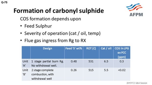
Carbonyl sulfide is produced during the cracking reaction and boils slightly below propane at -50°C (-58°F). Upon post-fractionation, it concentrates predominantly in propylene. COS (carbonyl sulfide) level in FCC LPG most strongly corresponds to the sulfur in the feed. The amount usually rises with increased feed sulfur but is unpredictable. Typically, every 0.6 wt% in feed sulfur corresponds to nearly 7 to 8 ppm in COS in LPG. The exact path by which COS is formed in the riser is not very clear, but formation of COS involves CO and CO2. This formation predominantly depends on feed sulfur, severity of cracking, reaction temperature, and flue gas ingress from the regenerator (Rg) to the reactor (Rx).
In the units maximizing the yield of propylene, formation of COS is lower if propylene maximization is achieved by the addition of ZSM5 rather than by increasing reaction severity. Sulfur in the feed is the biggest contributor to COS formation, the concentration of H2S being directly proportional to sulfur in the feed. There is an option for reduction of COS formation by pretreatment of feed to minimize the feed sulfur content. COS formation is pronounced in partial combustion regenerators; hence, a full-burn regenerator may be a choice if the objective is COS reduction.
In Indian Oil, we are operating FCC units of different designs and configurations: partial-burn, full-burn, single and double regenerators, with and without a withdrawal well. I have tried to compare the data of two units of different designs. Unit A is a single-stage, partial-burn regenerator with no withdrawal well, while Unit B is a two-stage regenerator with complete combustion and a withdrawal well. The feed sulfur corresponding to Unit A is 0.48; the feed sulfur is 0.26 in Unit B.
Though it is difficult to directly correlate, as per our experience in the units with built-in design for complete combustion and with the withdrawal well (which provides defluidization of regenerated catalyst before it enters the riser), COS formation is less. Traditional treating with caustic solution is not very effective for removing COS from the hydrocarbon stream to very low levels. It can be removed by hydrolysis or the adsorption method. The COS hydrolyzer reactor converts COS to H2S, which is typically easily captured by caustic. COS, in traces, can be removed by guard beds of aluminum-based selective adsorbents.
DE GRAAF (Johnson Matthey Process Technologies)
COS contamination in propylene is a problem because small quantities can already make it suspect of polymer grades. COS is formed in the regenerator, but this can be carried over into the pores of the catalyst into the riser. And in the riser, the COS can react readily with water vapor to form H2S. Theoretically, it is possible to form COS from the reaction of H2S and CO. But if this reaction would take place, it is probably at a negligible phase. When you are studying how much COS can be present in the propylene, you see that a wide span of values can be present, revealing that there is probably not so much of a chemical catalytic effect as an operational effect.
COS is a light boiling component; but if it ends up in the LPG, it has a lighter boiling point than propylene and propane. So, any COS that is still present in the LPG will end up in the propylene stream. If you have any change in the amount of LPG you make, you will probably have to pay a lot of attention to the split between LPG and dry gas, because any dry gas and COS that can slip into the LPG will end up in the propylene stream. So, for example, when you start using ZSM-5 additives or increase conversion in your unit, detailed monitoring of your LPG and dry gas splits probably will help prevent a lot of COS from ending up in your propylene.
YORKLIN YANG (BASF Corporation)
COS is a species formed in the FCC due to a number of reactions between CO, CO2, coke, water, sulfur, hydrogen sulfide, and possibly other compounds. COS fractionates out in the propylene (C3=) stream in FCC gas plants and often causes corrosion problems in LPG. Carbonyl sulfide inhibits selective hydrotreating and the activity of gasoline hydrotreating. Polymer-grade propylene product specification for COS is often in the ppb (parts per billion) range. In the recovery section, the majority of the carbonyl sulfide fractionates out with the propylene product.
Industry experts believe that COS forms in equilibrium with the materials in the riser. It is believed that the key to minimizing the formation of COS is to minimize the undercarry of regenerator flue gas with the regenerated catalyst. Partial-burn units typically have more problems with COS than full-combustion units. In practice, COS minimization could be done by using a gas other than air for regenerated catalyst standpipe aeration, as well as by having a proper hopper to degas the regenerated catalyst before it enters the standpipe. Any free H2S entering the riser is also a known COS producer.
Bart just made some very good comments. I have a couple of experiences related to this question. Most cases are related to high severity FCC which are run with a much higher riser outlet temperature for making a polymer-grade propylene product, and COS is really the main issue. One example is that it is common to use dry air for regenerated standpipe aeration. If we could switch to nitrogen or steam for standpipe aeration, that would reduce at least 20 to 50% of COS formation.
Another suggestion Sanjiv mentioned is that if you have a catalyst withdrawal well, the flue gas will be entrained with catalyst. However, the purge gas for the catalyst well could be switched to use nitrogen or steam instead of air, tremendously reducing the amount of COS.
In the FCC treatment system, COS may be removed by adsorption on a catalyst bed or with an amine (MEA or DEA) system. Approximately 80% of the COS is hydrolyzed in the amine unit where it reacts as carbon dioxide and hydrogen sulfide. The remaining 20% forms amine stable salts. For a lower COS content inlet, like 1 ppmw (parts per million by weight), it will be more economical to install a molecular sieve reactor bed than an amine system. At some point, the economics tip toward an amine system when the concentration of COS in the FCC off gas is high enough to require a reactor bed which has a size and equivalent capital and operating expense that exceeds the cost of the equipment and operation of an amine system.
ROBERT (BOB) LUDOLPH [Shell Global Solutions (US), Inc.]
I want to share an experience with a full-burn FCC that I had some years ago. The unit had a serious catalyst loss problem. The refinery chose to import e-cat to make up for the losses. The e-cat also contained SOx reduction additive, an additive that the operator of the full-burn FCC had not been adding previously. Coincidentally, it was observed that the COS content of the PP (propane propylene) increased after the e-cat was added to the inventory. The gas plant included a deethanizer which was later operated differently to manage the COS but resulted in a loss of propylene to the fuel gas system. The combination of the e-cat (containing the SOx reduction additive) with the unit inventory catalyst led to a COS issue that was unexpected. The additive was the suspected cause but could not be proven. So just a warning: If you are going to import e-cat for makeup, review the properties carefully and understand what catalyst additives might be present. Identify any risks and lay out the actions for remediation.
EMERSON FRY (Delek Refining, Ltd.)
Those are excellent suggestions. I will simply add that a KOH (potassium hydroxide) bed can also be effective in removing COS or at least keeping it dry enough to prevent it from hydrolyzing to H2S.
BART DE GRAAF (Johnson Matthey Process Technologies)
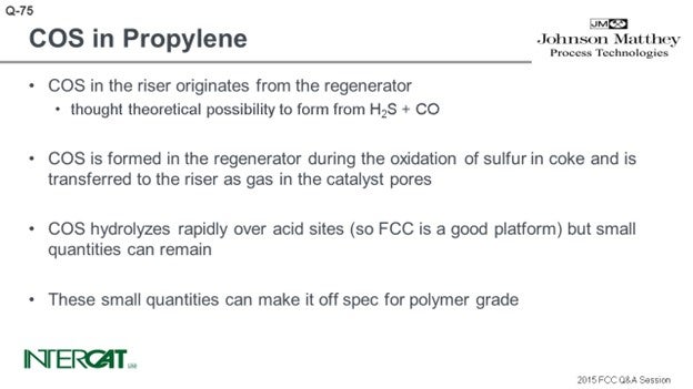
COS contamination in propylene is a problem as small quantities can make it off spec for polymer grade. COS in FCC products is typically formed in the regenerator. COS is formed in the regenerator during the oxidation of sulfur in coke and is transferred to the riser as gas in the catalyst pores. COS is very unstable in the presence of steam; it readily hydrolyzes over acid sites into H2S. Theoretically, it is possible to form COS from the reaction of H2S with CO over acid sites, though this reaction, if it takes place, is probably negligible in the riser.
Concentrations of COS in propylene streams vary over various orders of magnitude, which is unlikely to be a chemical effect only. Chemical composition of feeds and catalysts in FCC units show a smaller span in variation than COS in propylene. COS concentrations in propylene are a function of the efficiency in the split between fuel gas and LPG. Any COS that has not been removed from LPG will effectively end up in the propylene stream, as propylene is the lightest boiling component in LPG (see table). Therefore, with every change in wet gas production, the gas plant requires careful monitoring to minimize COS concentrations in propylene.
|
|
Boiling Point |
|
COS |
-58.4°F (-50.2°C) |
|
Propylene |
-53.7°F (-47.6°C) |
|
Propane |
-44.2°F (-42.2°C) |
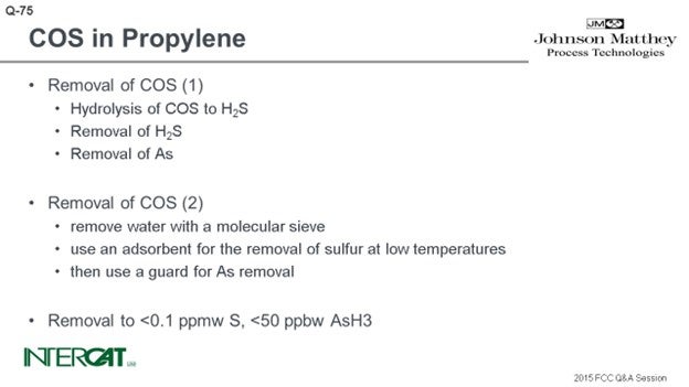
For the removal of COS there are two main basic routes. In the first, COS is hydrolyzed to H2S over an acidic catalyst. H2S is removed from the stream with polishing adsorbents. Thereafter, any as (arsenic) species are trapped in a guard bed. In the second route, water is removed from the gas stream with a molecular sieve. Thereafter an adsorbent is used for sulfur removal at low temperatures, and a guard bed is used for as removal. Removal efficiencies with either route is up to less than 0.1 ppmw (parts per million by weight) S, and less than 50 ppbw (parts per billion by weight) AsH3 (arsine) in the product.
SANJIV SINGH [Indian Oil Corp Ltd. (IOCL)]
Carbonyl sulfide (COS) is produced during the cracking reaction. It boils slightly below propane at minus 50°C (-58°F). Upon post-fractionation, the COS concentrates in the LPG, propane-propylene, and finally in propylene as the distilled cuts narrow in boiling range. COS concentrations in the LPG stream may range from 5 to 100 ppm. The COS level in FCC LPG most strongly corresponds to sulfur in the feed. The amount usually rises with increased feed sulfur but is very unpredictable. Typically, every 0.6 wt% sulfur in the feed corresponds to 7 to 8 ppmw COS in the debutanizer overhead liquid.
The exact path in which COS forms in the riser is not clear. A few possibilities are:
H2S + CO2 è COS + H2O
2CO + 2S è 2 COS
3 FeS2 + 4 CO2 + 2 CO è Fe3O4 + 6COS
SO2 + 3 CO è COS + 2 CO2
The formation of COS predominantly depends on the following,
-
Feed sulfur,
-
The severity of cracking (cat/oil ratio and temperature), and
-
Flue gas ingression to riser.
In the case of units maximizing the yield of propylene, the formation of COS will be lower if it is achieved by the addition of ZSM-5-based additive rather than the case with higher reaction severity.
Sulfur (S) in the feed is the biggest contributor to COS formation. The concentration of H2S will be directly proportional to S in the feed. The option for reduction of COS formation is pretreatment of feed to minimize the sulfur content. In our experience, COS formation is pronounced in partial-burn regenerators. Hence, full-burn regeneration may be an important consideration to minimize COS formation, especially in high propylene FCC units, due to stringent COS specification in propylene product. Some polymerization catalysts are sensitive to as little as 5 ppb COS. In an operating FCC unit, COS produced in the riser can predominantly be controlled by controlling feed sulfur.
IOCL operates FCC/RFCC units of different designs and configurations, e.g., partial- and full-combustion regenerators, with and without withdrawal well, single- and double-stage regeneration, etc. To assess the impact of parameters (other than feed sulfur) on the COS content in FCC LPG, the actual data of two units is compared below.
|
|
Design |
Feed ‘S’ wt% |
ROT* (°C) |
Cat/oil |
COS in LPG ex FCC (ppm) |
|
Unit A |
1-stage partial-burn regenerator, no withdrawal well |
0.42 0.48 0.67 |
531 |
6.5 |
0.15 0.30 0.35 |
|
Unit B |
2-stage complete combustion, with withdrawal well |
0.26 0.49 0.66 0.77 0.80 |
515 |
5.5 |
<0.02 <0.02 <0.02 <0.02 <0.02 |
* ROT (reactor outlet temperature)
Though it is difficult to directly correlate, our operating experience has clearly indicated that the units with a built-in design for complete combustion and defluidizing regenerated catalyst, by way of incorporating withdrawal well and reducing flue gas carryover from the regenerator to the reactor, are likely to have significantly lower COS formation.
The traditional method of treating with caustic or amine solution is not effective in removing COS from a hydrocarbon stream. COS can be removed by hydrolysis or adsorption methods.
There are several catalysts available for hydrolysis of COS into H2S and CO2. The COS hydrolysis reactor, located upstream of the caustic treater, converts COS to H2S, which is then easily captured by the caustic. COS in traces can be removed by guard beds consisting of alumina-based selective adsorbents. Some of the COS is hydrolyzed in the amine absorber (down to about 10 ppmw). If COS levels in the C3 product are desired to be less than 1 ppmw, there is usually an amine settler downstream. The amine settler uses the MEA+NaOH (monoethanolamine plus sodium hydroxide) solution to drive the hydrolysis of the remaining COS down to 1 ppmw or less. The C3 stream then goes to an adsorbent bed to remove the remaining COS.
NIKOLAS LARSEN [Marathon Petroleum Company (MPC)]
Several impurities are expected in a refinery propylene stream including carbonyl sulfide (COS), carbon disulfide (CS2), hydrogen sulfide (H2S), mercaptans (RSH), and arsine (AsH3). Removal of these contaminants is often required for reasons of safety, corrosion, and product specifications; to prevent poisoning of downstream catalysts; and, to meet environmental requirements. In one MPC unit, the treatment and/or removal of these impurities is accomplished through chemical reactions taking place in hydrolysis reactors, a propylene scrubber, and an arsine treater.
Hydrolysis Reactor and Propylene Scrubber Chemistry: The sulfur impurities that are present must be removed to meet product specifications. The spec for COS in this unit that produces polymer grade propylene is 40 ppbv (parts per billion by volume). Optimal water concentration for the hydrolysis reaction is two to three times the molar concentration of COS in the feed. In the unlikely event that the feed water content is less than optimal, hydrolysis reaction water can usually be injected upstream. The hydrolysis reactor catalyst promotes the hydrolysis of COS – and, to a lesser extent, CS2 – to carbon dioxide and hydrogen sulfide through the reactions shown below:
COS + H2O à CO2 + H2S (1)
CS2 + 2 H2O à CO2 + 2 H2S (2)
The products of reactions (1) and (2), being contaminants themselves, require removal. A 25 Baume (Be) caustic solution is injected downstream of the hydrolysis reactors, and mixing of the two streams occurs in a downstream static mixer. The caustic reacts with CO2, H2S, and mercaptans, as shown in the reactions below:
CO2 + 2 NaOH à Na2CO3 + H2O (3)
H2S + 2 NaOH à Na2S + 2 H2O (4)
RSH + NaOH à RSNa + H2O (5)
The products of reactions (3) through (5) are water-soluble rather than hydrocarbon-soluble; thus, they are contained in the spent caustic phase at the bottom section of the propylene scrubber. The caustic phase is recirculated through the mixer until spent. At this time, the spent caustic is drained, and fresh caustic is reintroduced to the system. Any entrained caustic in the process line leaving the scrubber can be removed by a downstream sand filter.
Arsine Treater Chemistry: Although only trace amounts of arsine are expected in a refinery propylene stream, enough is present to cause increased polymerization catalyst consumption resulting in decreased polymer quality in a downstream polymer unit. Arsine treater catalyst in this unit is composed of copper oxide, aluminum oxide, and aluminum silicate. The arsenic reacts primarily with the copper oxide in the reaction below:
AsH3 + 3 CuO à Cu3As2 + 3 H2O (6)
The arsine treater catalyst is also effective in the removal of sulfur containing impurities such as COS, H2S, CS2, and mercaptans (RSH) which may still remain in the hydrocarbon stream. These compounds primarily react with the copper oxide (CuO) as shown below:
COS + CuO à CuS + CO2 (7)
H2S + CuO à CuS + H2O (8)
RSH + CuO à CuS + ROH (9)
CS2 + 2 CuO à 2 CuS + CO2 (10
Year
2015
Process
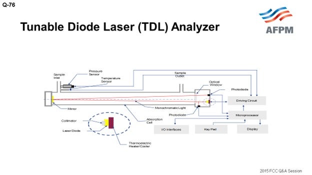
Question 76: What has been your experience with respect to FCC flue gas analyzers using tunable diode lasers or alternatives? Any specific advantages of tunable diode laser (TDL) analyzers with respect to installation, operational service requirements, and/or reliability?
SINGH (Indian Oil Corporation Limited)
Presently, we are not using any tunable diode laser analyzers for FCC units. We typically use ultraviolet or infrared analyzers which have their own reliability issues and have not been very dependable in FCC service. We are using TDL (tunable diode laser) analyzers in our CCR (continuous catalyst regeneration) unit. Our experience with them in the CCR unit is extremely good. These are non-contact-type analyzers in which a small quantity of the sample enters from one side and exits from the other side. In these analyzers, the sample stream does not come in direct contact with any part of the analyzer, which greatly improves reliability. These TDL analyzers do not drift or require regular calibration checks.
FOSHEE [Shell Global Solutions (US)]
Sanjiv did a good job covering this question, but I will just add Shell’s experience. Shell has three sites with tunable diode laser analyzers in the flue gas line. Of these sites, one of the sites has tunable diode lasers as part of the safeguarding system for their ESP. This particular site does not have an expander. Another site has tunable diode lasers in place with the intention of using them for safeguarding their ESP, but they also have an expander and have noticed some signal irregularities when they put in walnut shells to clean the expander blades. So as a consequence, they now just use the tunable diode lasers for monitoring. A third site has tunable diode lasers in place for monitoring purposes only. This particular site does not have an ESP.
I will say that, in general, Shell’s overall experience with tunable diode lasers has been positive. They have a lot of benefits including their accuracy and reliability, combined with the benefit of requiring less maintenance. Some of the problems the tunable diode lasers have been the occurrences of laser transmittance issues due to particulates in the flue gas. This can usually be resolved with a proper purge rate. We are still searching for a solution to the irregular signal that occurs during the expander blade cleaning. High temperatures can sometimes cause problems for tunable diode lasers, but this can usually be solved with the heat shield. Also, vibration can sometimes be an issue, but not always with the tunable diode lasers.
EMERSON FRY (Delek Refining, Ltd.)
Most of the time when I see an application like this, it is typically on the flue gas line itself. On your diagram, it looks like you have a sample line coming off with it. So, is this another concern with condensation damaging the instrument?
SINGH (Indian Oil Corporation Limited)
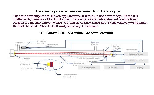
I cannot say this because we are not using it for FCC at the moment. We are using this analyzer only for moisture analysis in the CCRU (continuous catalytic reforming unit) recycle gas. In this service, our experience has been very good.
SANJIV SINGH [Indian Oil Corp Ltd. (IOCL)]
At present, we have no tunable diode laser (TDL) analyzers installed in our FCC units. Instead, there have been UV- (ultraviolet) or IR (infrared)-based analyzers in the flue gas circuit which have proven to be problematic and not very reliable. TDL is a single-line ‘monochromatic’ spectroscopy technique that offers various measurement advantages including highly stable calibration; continuous, fast in-situ measurement; and avoidance of cross-interferences from other gases. The TDL analyzer has improved technology with no drift and does not require calibration. The suppliers of the tunable diode laser flue gas analyzers claim the following benefits:
-
In-situ analysis without sample conditioning,
-
High dynamic range and accuracy,
-
Fast response (1 to 20 seconds),
-
High spectral resolution,
-
Process pressure/temp (up to 20 bar/1500°C),
-
Optical measurement (no sensor contacts with process), and
-
Practically calibration-free.
TDL analyzer vendors may be directly contacted to find out further details and reference units.
Though IOCL does not have direct experience with TDL analyzers in FCC, we are using the same in different applications; and so far, our experience has been very good. A TDL analyzer is being used for moisture measurement in a CRU unit, and the performance has been very satisfactory.
NIKOLAS LARSEN [Marathon Petroleum Company (MPC)]
MPC does not have any TDL analyzers in FCC flue gas service. However, we do have a few installed-on process heaters that are used to measure O2, and we are happy with their performance. In FCC flue gas service, MPC has one unit that utilizes an extractive system. The analyzer is the ABB AO2000 platform with a Magnos 106/206 Paramagnetic oxygen analyzer and an Uras 14/26 nondispersive infrared CO analyzer. This analyzer is mounted on the deck at the duct, so our sample line is very short: probably in the 10- to 20-foot range. Overall, we have been pleased with this setup.
Year
2015
Process
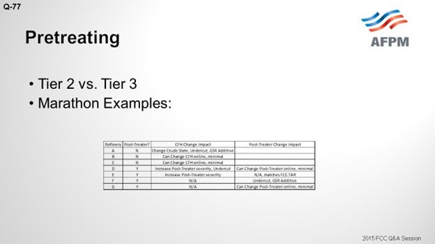
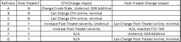
Question 77: When relying primarily on FCC feed pretreating to meet FCC gasoline sulfur specifications (current or future Tier 3), how do you manage feed pretreater outages?
LARSEN [Marathon Petroleum Corporation (MPC)]
Marathon relies on feed pretreating for three of our FCCs, which will all continue post-Tier 3 regulation implementation. Looking at the difference between Tier 2 and Tier 3, we see that when the annual average ppm in gasoline goes down from 30 to 10, the maximum per gallon, I believe, does not change from 80. So technically, you would not have to change how you currently handle your cat feed hydrotreater outages, but I think I would put some numbers to it. If you run 10 ppm and take a four-week FCC feed pretreater outage, you will have to run about 4 ppm for the rest of the year to make up for it, which is challenging.
I pooled our refineries and gathered our experience. On the slide, you can see what we plan to do. In a few of our cases, we have invested in some additional reactor volume to be able to have minimal impact on the FCC. In general, painting in a rather broad stroke, undercutting and gasoline sulfur reduction additives are not generally part of our normal operation strategy to comply with Tier 3. All of our refineries will be able to make 10 ppm gasoline to generate credits, which is also an option.
REYNOLDS (Phillips 66)
I currently live in this situation right now. We totally rely on pretreating to meet our FCC gasoline sulfur. We try to have several days’ worth of minimum FCC rate in tankage. In case there is a little upset with the gasoline hydrotreater, we could keep the FCC running. If there is a major outage, we have to manage our tankage. That is really our only option. We are in an isolated area, so we cannot export gasoil. Lastly, we are very aggressive. If there is an issue with that gasoline hydrotreater, we will cut the rate in the FCC quickly just to try to stay ahead of it and give us all the time we can to keep running.
RAMA RAO MARRI (CB&I Lummus Technology)
I have one comment. Normally, more and more FCCs are operating with the feed preheater. So, we recommend considering that over 10% of the feed coming from the feed hydrotreater will go to the tank for handling emergency situations under Tier 3. Without the feed preheater, it is difficult to maintain the gasoline sulfur requirements. Instead, having 10% of the feed go to the tank and stored for a couple of days would help you ease out of the situation and still maintain the refinery gasoline sulfur limits.
COLIN BAILLIE (Grace Catalysts Technologies)
Refiners have created operating flexibility during hydrotreater outages by utilizing Grace’s clean fuels GSR® additive technology as a part of their short-term operating strategy. Proper management of FCC feed hydrotreater outages becomes increasingly important as more and more refiners rely on hydrotreating to meet their per-gallon gasoline sulfur limits. Running at higher severity increases the frequency of turnarounds. Conventional methods of ensuring that the gasoline pool stays below the sulfur limit during the hydrotreater turnaround are purchasing low sulfur feed or reducing FCC throughput. Either approach can significantly reduce refinery profitability. An alternative is to use one of Grace’s gasoline sulfur reducing technologies during the outage to provide operational flexibility while maintaining sulfur compliance and profitability.
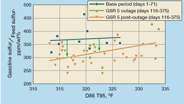
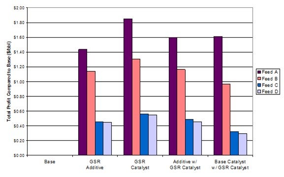
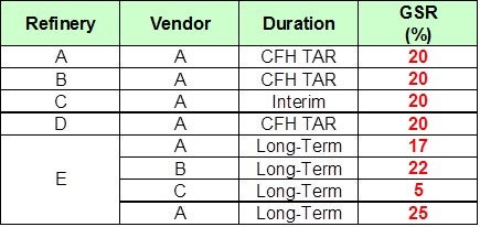
One such example of a refiner who used Grace’s GSR® 5 sulfur reduction additive during a feed hydrotreater outage is shown in Figure 1. The refiner was able to process higher than typical feed sulfur and maintain gasoline pool sulfur compliance. Use of GSR® 5 began two months prior to the 45-day feed hydrotreater outage. During that time, feed sulfur increased by as much as 35%. The three periods represented are typical operation (Base Period), GSR® 5 before and during the outage where gasoline sulfur reduction ranged from 20 to 25%, and finally GSR® 5 following the outage. The customer estimated that use of GSR® 5 netted $1.7 million of savings during the hydrotreater outage. The results were so encouraging that the customer elected to continue using GSR® technology, switching to a SuRCA® catalyst and operating with post-outage feed sulfur 10 to 15% higher than the typical operation. This change to their operation grew annual profits by approximately $8 million.11
Figure 1: GSR® 5 delivered 25% gasoline sulfur reduction during a feed HT outage
Grace’s clean fuels technologies include D-PriSM® and GSR® 5 FCC additives, as well as SuRCA® FCC catalysts, which are the result of almost two decades of innovation. Grace’s clean fuels technologies have been used in more than 100 FCC applications worldwide delivering 20 to 40% sulfur reduction in FCC naphtha in both full- and partial-burn operations. The D-PriSM® and GSR® additive technologies are used at a 10 to 25% loading in inventory, whereas the catalytic solutions are a customized 100% drop-in replacement for your base catalyst. Grace’s clean fuels technologies allow for a truly customized solution for the management of feed pretreater outages, or the compliance of environmental regulation.
NIKOLAS LARSEN [Marathon Petroleum Company (MPC)]
The maximum per-gallon sulfur specification of 80 ppm does not change with Tier 3, but the annual average drops from 30 to 10 ppm. Since the per-gallon cap does not change, in theory, Tier 3 does not change how FCC feed hydrotreater (CFH) outages are handled. However, Tier 3 will require operation at less than 10 ppm sulfur to meet the annual average target if the CFH is down. For example, if you ran at the 80 ppm gasoline sulfur limit for a four-week CFH outage, you would need to average 4.2 ppm the rest of the year to meet the 10 ppm pool average. All MPC refineries plan to achieve less than 10 ppm gasoline pool sulfur during normal operation and will generate credits which will be used to offset CFH and gasoline post-treater outages.
Year
2015
Process
Question 78: Under what conditions do gasoline sulfur reduction additives and catalysts reduce sulfur in gasoline, and by how much? What is the lowest gasoline sulfur level for which the gasoline sulfur reduction products are effective? At this gasoline sulfur level, please quantify the gasoline sulfur reduction and the amount of additive/catalyst required.
LARSEN [Marathon Petroleum Corporation (MPC)]
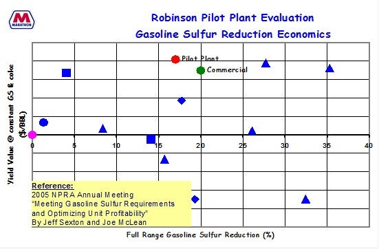
That is a very long breath of a question. [Laughter] I will summarize some of the Marathon’s findings on gasoline sulfur reduction additives. We have done a lot of testing in our pilot plant in the past. Some of that has already been presented. You can reference Jeff Sexton’s response to Question 46 of the FCC session of the 2009 AFPM Q&A Question if you want to see a little more data. But in general, we already mentioned our pretreat/post-treat scenarios and went over how gasoline sulfur reduction additives work. I will hit on the mechanism of how we believe they work, some of the variables that would impact their performance, and then some of our more recent testing and applicability at already low gasoline sulfur levels.

In terms of the mechanism, in our pilot plant testing, we have seen that recombinant reactions play a large role. So, no matter what feed sulfur species end up going into pilot plant, we get the same gasoline sulfur species coming out the back end, thereby emphasizing that the recombinant reactions in the riser play a large, dominating role in generating gasoline sulfur species. The additives we tested, for the most part, will crack the gasoline sulfur species into H2S. We charted a few of them on the slide. I believe there is other technology that will move the sulfur down into coke.

Several variables can cause an effect. Bart already mentioned vanadium as being one of them. There is a trend on the next slide showing one of our units with operation at low and high vanadium levels and the impact on the gasoline sulfur to feed sulfur ratio. You can see it is very significant. We have done testing with nitrogen and have also noticed big effects in the gasoline sulfur. In general, we have tried many types of gasoline sulfur reduction catalysts and found two that worked well for us. It is important to recognize the importance of balancing the ability of the GSR (gasoline sulfur reduction) to reduce sulfur without having any adverse yield impacts.

We have done economic modeling and confirmed the pilot plant testing with actual unit post-audits to find additives that work best for us, and we have then gone on to do some of our testing recently at already low gasoline sulfur levels.

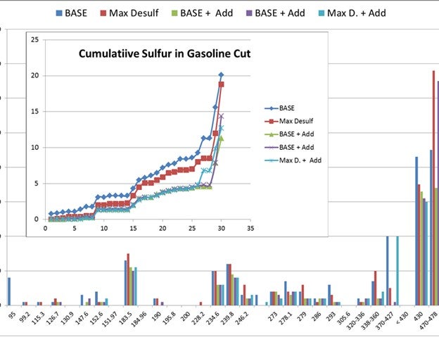
On the next slide, I apologize for the scale being cut off on the left-hand side, but I believe it just goes from zero to 8 ppm. Those are all different sulfur speciation concentrations of the different molecules. You can see that the gasoline sulfur we are starting at is 20 ppm. This is full range gasoline sulfur concentration.
We have seen about the same reduction in gasoline sulfur that was previously seen when starting with higher levels of gasoline sulfur. So, it appears that the additives we have tested worked in about the same range, even when starting with less gasoline sulfur or reloads. I know the trend is a little busy. There are a couple of data points shown: a base case, a max desulfurized FCC feed case, and then a couple cases with additive that show the incremental reduction in gasoline sulfur.

DE GRAAF (Johnson Matthey Process Technologies)
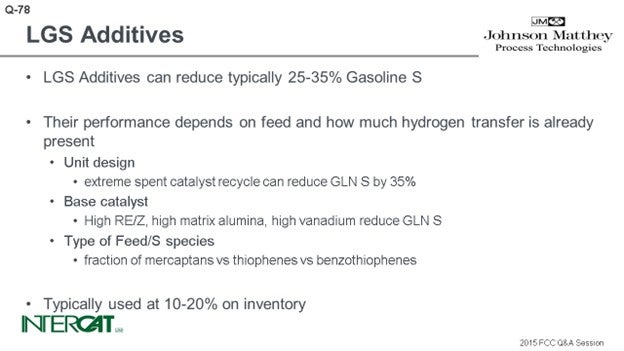
Additives can help to reduce gasoline sulfur 20 to 35%, but they cannot perform miracles. Their performance depends on how much hydrogen transfer is already present in the system. There are various contributing factors to the success of this reduction.
I visited a refinery in China which had two different FCC units. They processed the same feed and used the same base catalyst. However, one was a unit that had a sort of fluid bed in the unit, and the other was more of a typical side-by-side FCC unit. At similar conversion level, the unit that had a sort of fluid bed in the riser had 35% less sulfur in gasoline due to the huge spent catalyst recycle caused by the fluid bed.
The base catalyst contributes to hydrogen transfer as well. You can optimize the amount of rare earth. The rarer earth you put in the catalyst, the higher the acid site density in the zeolite, which will result in more hydrogen transfer. A high alumina catalyst helps reduce sulfur; and like I mentioned before, high vanadium levels also help to reduce gasoline sulfur.
Another factor is how much hydrogen the feed brings in itself. If there is a lot of hydrogen transfer from the feeds, the performance of the gasoline sulfur additive will be affected. It will be more of an uphill battle than if there is a low amount of hydrogen transfer caused by the feed. Mercaptans, thiophenes, or hydrothiophenes are easier to remove than benzothiophenes. Typically, you would use about 10 to 20% of gasoline sulfur additive in on inventory, but we have seen that gasoline sulfur additives are effective over a very wide range of applications.
MELISSA CLOUGH (BASF Corporation)
I will just add a couple more comments. Both Nik and Bart did a good job talking about a number of key aspects, including speciation. It is important to understand how or what kind of game plan you need, in terms of gasoline sulfur reduction additives. So, the usage of the additive, like Bart said, is about 10 to 20%. Another point to consider is preblending, so we can avoid diluting the base catalyst.
And then, Nik did mention part of that question that asks: When you already have low sulfur in the gasoline, what kind of reduction is still possible when using these additives? We just saw some testing results from Nik.
I want to add another story from the refinery experience side. Some of our customers in Japan are running very low sulfur feeds and treating gasoline sulfur reduction additives and are still seeing around 20% reduction. So even at already low gasoline sulfur, further reduction is still possible.
COLIN BAILLIE (Grace Catalysts Technologies)
Grace’s gasoline sulfur reduction (GSR®) additives are effective under a wide range of operating conditions in the FCC unit. There have been numerous case studies and references supporting the robust performance of GSR® technologies in which 20 to 40% gasoline sulfur reduction has been observed for a wide range of:
• Feed types,
• Feed sulfur levels, and/or
• Gasoline sulfur levels.
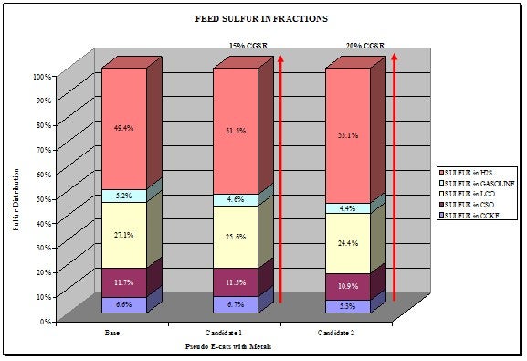
Grace’s GSR® technologies are particularly effective for removing mercaptans, sulfides, tetrahydrothiophenes, and thiophenes in gasoline. Benzothiophenes are harder to remove, while dibenzothiophenes generally remain unaffected under FCC operating conditions. Therefore, a key factor in determining the actual level of gasoline sulfur reduction is the identification of the sulfur species present in the gasoline. Figure 1 shows gasoline sulfur species distributions for various non-hydrotreated feeds (U1-U3) and hydrotreated feedstocks (H1-H3). All of the gasoline streams contain the same types of sulfur species, although their distribution varies. Grace’s GSR® technologies would result in gasoline sulfur reduction for all of these streams, though higher reductions would be observed for those containing a lower proportion of benzothiophenes, highlighting the suitability of GSR® technology for various feed types.
Feed sulfur type plays a bigger role than feed sulfur content in the level of gasoline sulfur reduction observed. Multi-ring aromatic thiophenes in the feedstock will not contribute to sulfur species in the FCC gasoline, so they have little impact on subsequent GSR® performance. In contrast, alkylbenzothiophenes in the feedstock undergo dealkylation resulting in benzothiophenes in the gasoline. These are harder to remove than the thiophenes, sulfides, and mercaptans that result from the alkylthiophenes and cyclic sulfides in the feed. Therefore, although Grace’s GSR® technologies will provide gasoline sulfur reduction for all feedstocks, those with a higher proportion of alkylthiophenes compared to alkylbenzothiophenes will see a greater gasoline sulfur reduction.
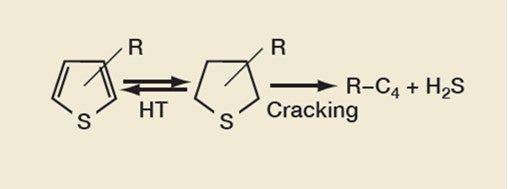
Removing thiophenes is a key part of gasoline sulfur reduction, the reaction pathway of which is shown in Figure 2. The FCC catalyst component catalyzes the hydrogen-transfer (HT) reactions between thiophenes and tetrahydrothiophenes (THT). GSR® technology works by increasing the cracking of THT into hydrocarbons and hydrogen sulfide.
Figure 2: Thiophene Reduction Reaction Pathway
Any conditions that promote HT reactions are likely to be favorable for gasoline sulfur reduction. These include reduced riser temperature and increased pressure, as well as a catalyst with an optimized unit cell size, though this play less of a part than feed sulfur species. This is highlighted by the current users of Grace’s GSR® technologies that are achieving high levels of gasoline sulfur reduction operating under the following various conditions:
-
Riser Temperature: 965°F to 995°F
-
Feed Preheat Temperature: 430°F to 625°F
-
Cat-to-oil: 6 to 10 weight catalyst to weight of oil
-
E-cat Unit Cell Size: 24.27 to 24.32 Å
When considering the lowest gasoline sulfur levels for which GSR® products are effective, there are many interesting case studies from Japanese refiners who are producing gasoline with less than 10 ppm sulfur. In addition, many of these refiners operate their feed pretreater unit very severely, resulting in low FCC feed and gasoline sulfur levels. One such refinery had average gasoline sulfur levels of 13 ppm prior to the use of GSR® technology. After switching to Grace's SuRCA® catalyst technology, the refinery managed to achieve upwards of 30% reduction to control gasoline sulfur levels to below 9 ppm. SuRCA® is a tailored catalytic solution for gasoline sulfur reduction and is used as 100% drop-in replacement of the previous base catalyst, with no increase in catalyst addition rates required.
BART DE GRAAF (Johnson Matthey Process Technologies)
When additives are used in FCC to reduce gasoline sulfur, they typically reduce the sulfur content by 20 to 35%. Performance of gasoline sulfur additives depends on many variables: feed, unit design, and operation and catalyst composition. They are typically used at levels of 10 to 20% in inventory.
The type of sulfur species in feed and gasoline is important. Additives are more successful when the fraction of aromatic sulfur species in feed is lower. Sulfur from mercaptans, thiophenes, and hydrothiophenes is easier to reduce than that of benzothiophenes. Therefore, the gasoline cutpoint is an important parameter when determining the overall effect of gasoline additives. Because of the distribution of sulfur species over gasoline boiling range, additives are more successful at lower gasoline cutpoints.
Unit design can affect gasoline sulfur as well. Experiments have shown that in cases of extreme spent catalyst recycle (approaching bed cracking), gasoline sulfur can be reduced up to 35%.
Catalyst design can help mitigate gasoline sulfur. Hydrogen transfer helps reduce gasoline sulfur; therefore, catalysts containing high rare earth USY show lower gasoline sulfur. Separately, boehmite matrix has some tendency to reduce gasoline sulfur, too. Vanadium has some sulfur-reducing tendencies as well. If the catalyst contains high rare earth stabilized zeolite and high matrix content and is high in vanadium, gasoline sulfur additives will typically be less effective than for high zeolite catalyst with low rare earth stabilization and low matrix content. Some refiners have tried e-cat from resid operations as a sulfur reduction additive, as this e-cat typically contains all of the above. Sulfur in gasoline is reduced by using this e-cat; however, at the expense of other yields such as coke and dry gas. In the design of sulfur reduction additives, the functionality of sulfur reduction is optimized, whereas potential side effects are substantially reduced or eliminated.
NIKOLAS LARSEN [Marathon Petroleum Company (MPC)]
In a post-Tier 3 environment, MPC will have three units that will rely on cat feed hydrotreating (CFH) and four units with post-treaters (Prime-G) to meet gasoline sulfur targets. GSR additives have been used on four units with CFHs during catalyst change outages. GSR products from all vendors have been evaluated in our pilot plant. We have conducted commercial trials with three vendors and have extensive experience with two vendors. MPC has presented significant data in previous AFPM meetings (see Question 46 from 2009 AFPM Q&A) but will summarize here since it has been several years.
MPC’s pilot plant has been utilized to help understand the chemistry surrounding gasoline sulfur and additives. A few important findings resulted from our pilot plant studies:
-
Recombinant reactions of H2S and olefins in the riser play a predominant role.
-
Sulfur species in feed and gasoline are different.
-
FCC feed sulfur compounds have different conversion reactivities. Basic nitrogen lowers the conversion.
-
This effect is apparent from FCC feed studies with nitrogen spiked components
-
Identification of where sulfur goes when removed from FCC gasoline is vital.
The majority of GSR products we have evaluated crack up feed sulfur into the different species in the product sulfur. The chart below shows the distribution with different GSR products. The majority of the gasoline sulfur goes to H2S. However, there are other technologies that can do the opposite where you can move the sulfur into coke sulfur.
Vanadium on e-cat is an important variable affecting gasoline sulfur. The data shows the two base operations which represent a typical range of e-cat vanadium. The data points represent three GSR products from two vendors. Performance has resulted in a 20 to 25% reduction in gasoline sulfur. This unit has used a GSR additive for 10 years.

In addition, we evaluated the impact of different feeds and combinations of vendor additives in the pilot plant. An additive and catalyst system were evaluated separately and then combined. Both were based upon different technologies, and the hope was that they would be additive. This theorem was evaluated with four different feeds. The rankings will vary depending upon the feed type. However, we did not find a synergy combining vendor products.
It is important to understand all aspects of GSR additives. Some candidates demonstrate great GSR reduction but also have a coke selectivity penalty. MPC has had success with a compromise between GSR and yields and bases decisions upon overall economics. For the case below, the pilot plant predicted a 17% reduction with a 20% reduction seen commercially. A post-audit of the yields confirmed the pilot plant prediction.
MPC has demonstrated that a 20% gasoline sulfur reduction is possible on multiple units with different applications feeds. We have evaluated various vendor products and seen that some have worked; some have not. We found two products that we have used successfully commercially.
Given the lack of intensive research into GSR technology and a lack of trials on units with low feed sulfurs, MPC investigated the impact of GSR additives on already low sulfur gasoline. The study utilized additives at 30 wt% since the initial driver was to see if we could get a measurable response at very low base gasoline sulfur levels. As you can see, this study demonstrated more than 25% sulfur removal at this low-range base sulfur with two different additives. A challenge in studying such small levels of gasoline sulfur is measurement of the different sulfur species, many of which are less than 1 ppm.
MELISSA CLOUGH (BASF Corporation)
Gasoline sulfur reduction additives are a convenient method used to get gasoline sulfur levels closer to or meeting Tier 3 standards. This is an important consideration since 90% of the naphtha sulfur typically comes from FCC naphtha. The amount of removable sulfur depends on whether or not the FCC feed is hydrotreated. With hydrotreated feed, the sulfur in the gasoline cut is typically lower, but the sulfur that remains is more difficult to remove (aromatic sulfur). On the other hand, non-hydrotreated feed contains more sulfur, but that sulfur is easier to remove. Typically, saturates, mercaptans, thiophenes, and alkylthiophenes see good or reasonable conversion to H2S or coke with the use of an additive. Benzothiophenes, although present in lower quantities than other species, have much lower conversion rates and are harder to remove. Sulfur removal from benzothiophene of 15% or less is common with an additive. Overall, when looking at the entire sulfur species in FCC naphtha, an average of about 20 to 40% reduction across the entire boiling point range can be achieved with gasoline sulfur reduction additives. Typical loading is about 15 to 25% of the base catalyst. Additives can be synergistically combined with the base catalyst formulation to minimize activity loss via dilution effects.
Year
2015
Process
Question 79: For units that have experienced elevated losses leading to coarse inventory, what options exist to improve catalyst properties during turnaround? Describe your experience with purchasing external or classifying spent catalyst.
RUSSEFF (CVR Energy, Inc.)
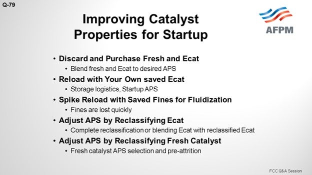
First, I would ask an additional question: Did you fix the problem during your turnaround activities that led to your coarse inventory and loss of the smaller particles? There are a lot of different paths to follow. The easy answer is to discard and purchase e-cat (equilibrium catalyst) that is correct for your average particle size and minimum fluidization velocity, which we have done. We have also put in a little fresh e-cat just to compensate for the abuse that it gets from the torch oil and activity; so when we start up, we will be more optimized, in terms of our blend.
Another option is to reload with your own saved e-cat: e-cat plus your fines. We have saved e-cat. Right now, one our units in Coffeyville is actually in turnaround, and we are looking into reloading with our own e-cat there. With units that have higher EPSs (electrostatic precipitators), you will have to blend something in order to blend down your particle size. Whether it comes from your plant internally or from the e-cat vendor is up to you.
I have seen the blending done, and I have seen the results. Some folks have spiked the reload of their e-cat with ESP hopper fines. Just a quick reminder: During startup, you are in flux; and for units that have problems with retention, be on the lookout for the fines, which tend to be visible quickly. I tend to avoid situations like that where we have those unnecessary and awkward conversations over the phone, so I would definitely not try that myself.
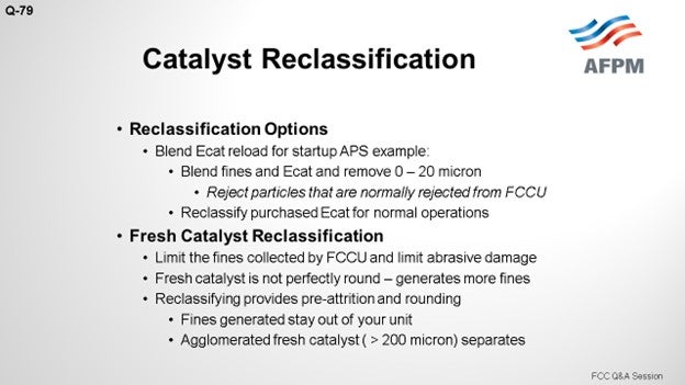
Another option is to adjust the APS (average particle size) by reclassifying the e-cat. We will get into more of that later. And then also, just because it came up, in terms of experience, reclassifying fresh cat is also an option. I will get more into that later. I apologize for the link on this, but it is a complicated issue.
At CVR, we watch our historical data. You want to optimize your load as best as you can. So, in terms of watching the e-cat and fines analysis, for me, it is like cracking. I cannot not look at it when it comes in, but there is a lot more valuable information in there other than just particle size and distribution; and just because your unit shut down on your current e-cat and particle size does not mean that starting up on that material because the APS is too large. Obviously, you will hit the typical issue there of bridging off a dipleg because your velocity is below your minimum fluidization for startup.
The bottom line is that every FCC is different. Each licensor has different approaches to the operations around the unit. There are a number of very old units in services today. You end up with one brand of feed nozzles and another brand of regenerator in the reactor. So, consulting with the vendors or licensors is always good. In some units, I feel like we could start up on gravel and billiard balls, while other units are really sensitive to average particle size. So it is important to get the historical data and consult with the licensors, especially in the separation's technology, to make sure you are starting up on the right particle size and have the right distribution.
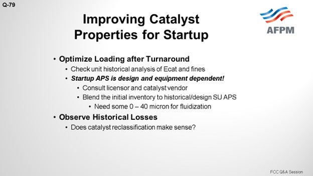
When, if ever, do you reclassify some of your loads? Some folks’ approach has been to observe that they lose all the zero-to-40 in their e-cat. So, they want to automatically just strip that out and say, “Oh, we do not need anything on startup.” Well, you still need some zero-to-40 for minimum fluidization velocity for your startup.
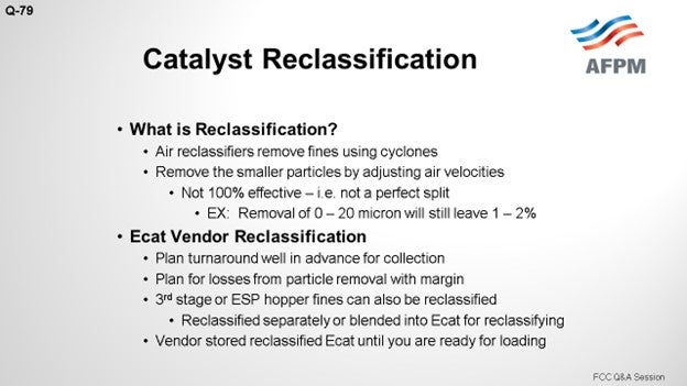
I think it is important to talk a little about reclassification because it is a newer topic and not at the forefront of everyone’s mind. A reclassification operation is important to understand because it gives us another tool. The more we understand about that tool, the more we can use it to our advantage. Typical reclassification just uses air as motor fluid running through the unit. I know I am oversimplifying this process; but if you are going to run through a set of a series of cyclones, adjust the velocity for the rejection. That is, it in a nutshell. So, if you do a zero-to-20 reject, you will still get some zero-to-20 particles. So, nothing is perfect, but we should understand the product.
If you are going to do reclassification, especially with your fines and e-cat, then you can choose between many different options. However, it is important to plan it in advance. We are currently reloading with our e-cat at our Coffeyville refinery, and we have managed to plan that well in advance. We set back the catalyst we need. If your average particle size is high compared to your minimum fluidization velocity for startup, you will have to blend that with some smaller particles; not necessarily the zero-to-20, but maybe somewhere in the 40 to 60 range, depending on the condition of your e-cat. Again, each unit is different. You have to plan for this.
It can be as simple as reclassifying your third-stage or your ESP fines, but you also may need to do more, such as dumping your third stage and ESP fines into your bulk e-cat and sending it to your reclassifying vendor. Or you could set those aside and do them separately. There are quite a few different options available. What works best for you depends on which particles you actually need.
Again, a typical approach is collecting your third-stage or ESP fines and dumping that into your e-cat, running it through a re-classifier, and then rejecting the particles that are typically rejected by the unit. The ESP fines either come out in the flue gas or in your main column bottoms, such as a zero-to-20 cut on your combined e-cat fines plus your e-cat. That is one option; there are probably many more alternatives, depending on your needs.
We are looking at reclassification itself because some folks are starting to do that for a normal operation. The idea of removing the fines material and finest-generating material before it comes into the unit is a highly desired effect. Units struggle with loss problems. I think we have all done that at one time or another. Removing that material before it goes into the unit can also help units that have experienced high losses. It actually do damage to the downstream equipment, slurry pumps, slurry piping, and flue gas system and causes flue gas cooler erosion, expander erosion, and overloaded ESPs. There are a lot of great reasons to remove that high fines material from your catalyst.
Emissions can also be decreased, which was a highlight for us. Our interest in this option was sparked when we did our stack test. Reclassification did great, and we managed to do the testing without ammonia injection or pass on our ESP. We were close enough that in the future, or with different regulations, we may end up having to take some other actions, part of which may include reclassification.
Freshly manufactured catalyst has all the tips on it. Regardless of the vendor, you will always get some inconsistency. Some are better than others, and I will leave that to you guys to debate. So, all of this imperfection breakoff is the major source of fines.
Additionally, during some catalyst manufacturing processes, you get some agglomeration of the larger particles. The air reclassifier is essentially the same as our separation's technology inside our unit except that it is not being done in our unit, which makes it highly attractive. The reclassification cyclones knocked off these tips and made more uniform particle size, essentially pre-tripping the catalyst. The normal source of fines that would leave the FCC unit from your regenerator and your main column bottoms are essentially limited or reduced prior to being introduced to the unit.
The air reclassifier: Our vendor, with whom I have been discussing this for reclassification of our fresh catalyst, also said that the agglomerated particles have a tendency to break off and round off, so you will get a gradual reduction in fines and a more even-sized distribution. That all sounds attractive, but nothing comes free, especially for us. So the other caveat, in addition to the increased cost, is that you will lose some of your purchased catalyst to the fines generation as a result of reclassifying.
I do not know the actual losses. However, after talking about this problem with other people, I came up with some questions that could help us in the future. It would be nice to see the reclassifiers run a couple loads of fresh catalyst from the catalyst vendors side-by-side to determine the actual attrition and calculate the particle size distribution before and after each run. The results would be very interesting for those of us in the industry who could really use that information. Due to emissions and pump erosion, maybe the future is getting a pass through a reclassifier before it actually gets to us. I do not know the effects on it yet, but it is certainly something that could be investigated.
FOSHEE [Shell Global Solutions (U.S.)]
That was a fairly complete answer. I will just add that Shell has experience with operating units for an extended period with elevated catalyst losses when the unit is close to turnaround: six to nine months away. When catalyst losses increase, the number of fines in the circulating catalyst decreases more than the other fractions, which reduces the ability of the catalyst to stay fluidized. During these times, Shell used a combined approach of additives, purchased e-cat with high fines content, or a fluidization aid in conjunction with the modification of the fresh catalyst for its particle size distribution (increasing the fines content of the fresh catalyst). This particular approach helped maintain fluidization before the turnaround and keep acceptable fines content, even during restart. After a startup, Shell has stopped the use of additives but has kept the high fines content fresh catalyst addition for several months in order to ensure that proper e-cat fines are maintained.
One of our FCC units has used another approach. This particular unit has a third-stage separator with a fourth-stage separator and hopper. The unit will periodically send the fines from the fourth-stage separator hopper back to the e-cat hopper, which results in alternating layers of e-cat and fourth-stage separator fines. At turnaround, when they are ready to put their e-cat back in the unit, they hire a third-party contractor to come and take the contents of their e-cat hopper and reclassify it to a specified particle size distribution; in particular, remove the zero-to-20 material.
REBECCA KUO (BASF Corporation)
Another option for units experiencing elevated losses is to use an additive that contains a high percentage of 20- to 40-micron material, such as EZ-Flow. Cyclones are typically designed to retain particles larger than 20 microns, so reintroduced microfines (0- to 20-micron material) from the ESP will just go back out the stack, and the coarse inventory would still remain an issue. Depending on how much additive is charged into the unit, the unit could see a 2 to 4 lb/ft3 (pound per cubic foot) drop in density in the standpipe and a 1- to 2-number increase in the Umb/Umf (minimum bubbling velocity to minimum fluidization velocity) ratio. Additionally, using an additive is a flexible option because once the elevated losses have decreased, the refinery can simply stop using the additive and move back to normal operation.
RYAN NICKELL (Albemarle Corporation)
I want to comment on the use of the fluidization additives. It is particularly advantageous to utilize an additive that has active cracking components in it. If you do that, you can certainly utilize aggressive injections to keep the unit up and running without dilution effects. Albemarle offers the SMOOTHFLOW™ product, which is described in the Answer Book.
ADAM KASLE (BP Products North America Inc.)
I have had experience with a couple of units that have had loss problems during operation which resulted in a loss of fines and an increase in average particle size. These units eventually shut down for one reason or another. When they tried to restart, we saw significant catalyst losses because of the poor particle-size distribution. I agree with what other people have said about using these additives, which you can probably get from any of the vendors. These additives provide a good option for quickly increasing the 20-to-40-micron particle content of the inventory to regain the fluidization properties, which are very important to keep the cyclones – and especially the secondary cyclone diplegs – fluidized during startup. If you are just buying e-cat from someone or buying fines, specifically, you will need to either consider classifying the catalyst or looking closely at the source. You certainly do not want to add a lot of zero-to-20-micron fines to the unit.
I worked with one unit that added an e-cat that someone had combined with ESP fines before selling it. The e-cat had a high zero to 40 fines content, which the refinery thought would be good, but most of this was less than 20 microns. The microfines in the purchased e-cat could not be retained by the reactor cyclones, so this material ended up in the bottom of the main fractionator and almost immediately plugged the slurry filter.
WARREN LETZSCH (Technip USA)
We get fixed on how much 0-to-40 micron catalyst is in the inventory. You need 10% to run the unit well. And as Bob Flanders used to say, “Purgatory was trying to run a Model IV with less than 10% fines in it.” What I would suggest is certainly nothing smaller than 20 microns. But frankly, if you did add 20- to maybe 60-micron catalyst, you would reduce the average particle size and find that your average particle size. The very larger particles – those over 100 microns – that are building up in the inventory will really start causing fluidization problems.
The advantage of taking out the 0-to-20 micron material is that you are likely to retain a lot more of this lighter or smaller catalyst that you were putting in. In my ideal world, I live in a place where you would have an FCC unit so tight that the average particle size would be 55 or 60 microns, which would circulate very well, and the bubbles would be smaller in the stripper and regenerator.
FOSHEE [Shell Global Solutions (U.S.)]
That was a fairly complete answer. I will just add that Shell has experience with operating units for an extended period with elevated catalyst losses when the unit is close to turnaround: six to nine months away. When catalyst losses increase, the number of fines in the circulating catalyst decreases more than the other fractions, which reduces the ability of the catalyst to stay fluidized. During these times, Shell used a combined approach of additives, purchased e-cat with high fines content, or a fluidization aid in conjunction with the modification of the fresh catalyst for its particle size distribution (increasing the fines content of the fresh catalyst). This particular approach helped maintain fluidization before the turnaround and keep acceptable fines content, even during restart. After a startup, Shell has stopped the use of additives but has kept the high fines content fresh catalyst addition for several months in order to ensure that proper e-cat fines are maintained.
One of our FCC units has used another approach. This particular unit has a third-stage separator with a fourth-stage separator and hopper. The unit will periodically send the fines from the fourth-stage separator hopper back to the e-cat hopper, which results in alternating layers of e-cat and fourth-stage separator fines. At turnaround, when they are ready to put their e-cat back in the unit, they hire a third-party contractor to come and take the contents of their e-cat hopper and reclassify it to a specified particle size distribution; in particular, remove the zero-to-20 material.
REBECCA KUO (BASF Corporation)
Another option for units experiencing elevated losses is to use an additive that contains a high percentage of 20- to 40-micron material, such as EZ-Flow. Cyclones are typically designed to retain particles larger than 20 microns, so reintroduced microfines (0- to 20-micron material) from the ESP will just go back out the stack, and the coarse inventory would still remain an issue. Depending on how much additive is charged into the unit, the unit could see a 2 to 4 lb/ft3 (pound per cubic foot) drop in density in the standpipe and a 1- to 2-number increase in the Umb/Umf (minimum bubbling velocity to minimum fluidization velocity) ratio. Additionally, using an additive is a flexible option because once the elevated losses have decreased, the refinery can simply stop using the additive and move back to normal operation.
RYAN NICKELL (Albemarle Corporation)
I want to comment on the use of the fluidization additives. It is particularly advantageous to utilize an additive that has active cracking components in it. If you do that, you can certainly utilize aggressive injections to keep the unit up and running without dilution effects. Albemarle offers the SMOOTHFLOW™ product, which is described in the Answer Book.
ADAM KASLE (BP Products North America Inc.)
I have had experience with a couple of units that have had loss problems during operation which resulted in a loss of fines and an increase in average particle size. These units eventually shut down for one reason or another. When they tried to restart, we saw significant catalyst losses because of the poor particle-size distribution. I agree with what other people have said about using these additives, which you can probably get from any of the vendors. These additives provide a good option for quickly increasing the 20 to 40 micron particle content of the inventory to regain the fluidization properties, which are very important to keep the cyclones – and especially the secondary cyclone diplegs – fluidized during startup. If you are just buying e-cat from someone or buying fines, specifically, you will need to either consider classifying the catalyst or looking closely at the source. You certainly do not want to add a lot of zero to 20 micron fines to the unit.
I worked with one unit that added an e-cat that someone had combined with ESP fines before selling it. The e-cat had a high zero to 40 fines content, which the refinery thought would be good, but most of this was less than 20 microns. The microfines in the purchased e-cat could not be retained by the reactor cyclones, so this material ended up in the bottom of the main fractionator and almost immediately plugged the slurry filter.
WARREN LETZSCH (Technip USA)
We get fixed on how much 0-to-40 micron catalyst is in the inventory. You need 10% to run the unit well. And as Bob Flanders used to say, “Purgatory was trying to run a Model IV with less than 10% fines in it.” What I would suggest is certainly nothing smaller than 20 microns. But frankly, if you did add 20- to maybe 60-micron catalyst, you would reduce the average particle size and find that your average particle size. The very larger particles – those over 100 microns – that are building up in the inventory will really start causing fluidization problems.
The advantage of taking out the 0-to-20 micron material is that you are likely to retain a lot more of this lighter or smaller catalyst that you were putting in. In my ideal world, I live in a place where you would have an FCC unit so tight that the average particle size would be 55 or 60 microns, which would circulate very well, and the bubbles would be smaller in the stripper and regenerator.
Year
2015
Process
Question 80: What are your Best Practices to address increased levels of conventional and “new” metals (V, Ni, Fe, Ca, Cu etc.) in the FCC that come from tight oil processing in the refinery?
DE GRAAF (Johnson Matthey Process Technologies)
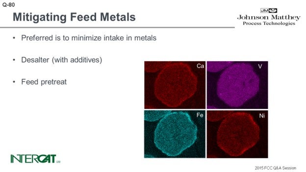
In the preferred case, you do not have any of those metals entering the FCC units. So, if you can optimize your desalter operation, and if there are various additive fresh suppliers who can help you, then you will be able to mitigate and reduce the number of metals entering the FCC unit. Another approach could be feed pretreat. But since the tight oil is typically already very light, this is probably an option that very few people would use.
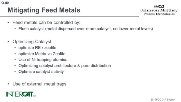
You have several ways to utilize your catalyst. If you want to reduce the overall metal effect, you can use a higher addition rate of fresh catalyst or add flushing catalyst on top of this. You will just have more particles over which the metals will be distributed. So on average, per particle, the actual metal level will be lower.
There are various options for making your base catalyst more metal resistant. For example, considering vanadium, if you want to make your catalyst more vanadium-resistant, then you can increase the amount of rare earth on your catalyst to make your zeolite more stable, or you can balance the activity by using more matrix. For nickel and copper, you can use high crystalline boehmite alumina because they can react with nickel and copper to form a nickel alumina spinel or copper alumina spinel. Those are more or less the conventional metals traps.
When it comes to iron and calcium, there are various options that catalyst suppliers can recommend. Since iron and calcium can form a eutectic and will close off the outer surface of the catalyst, the typical approach is to increase the amount of matrix and mesopores. Doing so will increase your diffusivity or accessibility. The term depends on your catalyst supplier, but it will help more feed to enter the catalyst.
Typically, catalyst suppliers also try to lower the amount of sodium off of your base catalyst. By reducing the amount of the zeolite and optimizing the amount of alumina, you will also postpone the point at which your catalyst will succumb to iron poisoning. For every catalyst, however, there is a point where iron and calcium concentrations will become too high. And at that point, you will either have to increase catalyst addition rate or use fresh catalyst.
Various refineries have also successfully used an external metal trap to mitigate iron effects. The benefit of that option is also that you retain your targeted yields from the base catalyst you have chosen. You will not have a fresh catalyst for this option because you will then be dependent on the quality of rare earth level and the presence of other additives off your fresh catalyst.
REYNOLDS (Phillips 66)
I completely disagree with everything Bart said. [Laughter] No, no! He gave a very complete answer. I will say that refiners should confirm that you are using the expertise of your catalyst and additives suppliers and your licensor. Bart’s response really covered the topic well.
LARSEN [Marathon Petroleum Corporation (MPC)]
I somewhat hate to mention it; but sometimes, “The solution to pollution is dilution.” You just have to flood the catalyst in there. I have seen a few units that have been limited by how much catalyst they can physically withdraw from their unit and then cool down, store it in a hopper, and ship out. In that case, as we experienced at one of our refineries, we installed a catalyst cooler to help, but not for that specific reason. I am sure Bart, or anyone from his organization, would be more than happy to talk to you if you are interested in that type of equipment.
JUSTIN IRICK (GE Water & Process Technologies)
This could also be a chemical vendor question. I would like to provide a counterpoint on this question. Nickel can be treated with antimony. Up to a certain threshold, it can be economically beneficial. It is not always appropriate and depends on the individual unit and the ever-changing feed. In the case of vanadium, the threshold is even higher than for nickel. Vanadium can be mitigated with tin and is cost-beneficial under certain conditions.
In the case of calcium and iron, we go back to the desalter where the pH modification has been shown to lower those contaminants by between 50 to 75%, depending on several different variables. And lastly, sodium is sometimes feed related or can be managed by caustic adjustment. Reducing caustic feed can lower sodium.
SHUYANG PAN (BASF Corporation)
This panel gave very good answers. To build on that, the majority of our customers use processed tight oil to some extent. We do see that the concentration of nickel and vanadium is not as high compared to conventional residue, but iron and calcium can be very high for some customers. Obviously, one of the solutions is to have an iron-tolerant catalyst. One of the factors is pore architecture, as Bart referred to earlier. Among our customers is a unit who runs as high as a 1.2 wt% e-cat iron. So far, we have not seen any adverse effects that could be attributed to the catalyst. So certainly, the application of catalyst technology proven to possess better iron tolerance is one solution to combat the problem of iron poisoning.
RYAN NICKELL (Albemarle Corporation)
I just want to emphasize that, certainly, a catalyst specifically designed for tight oils is a strong and advantageous way to go. In the Answer Book, you can read about Albemarle’s T-grade catalysts. We have AMBER T, and UPGRADER T, and ACTION T which fit a variety of applications. Regardless of whether you are blending this tight oil with a lighter gas oil stream, or even a very, very heavy resid stream, these are very good catalysts at managing iron.
BILGE YILMAZ (BASF Corporation)
I just want to add one point with regard to the comment on switching to low zeolite-content catalyst for dealing with iron issues. I personally have seen cases with high zeolite-containing catalyst formulations that do well in high iron environments. I believe the main point regarding dealing with iron is that you must look beyond just the size of the pores. You must evaluate the pore architecture and the hierarchy of the pores. This is making the distinction between porosity at the particle surface where iron is found and the pore volume distribution, including the interior of particle. It matters how pores are structured and where they are located. The pore distribution at the surface becomes, in my opinion, the key in dealing with these situations. Zeolite is there to serve a purpose. So if you can preserve the same zeolite content, and if you can address the high iron with the right type of catalyst, I think that would be the better solution because you would not have to give up on catalytic activities that you need.
PAUL DIDDAMS (Johnson Matthey INTERCAT)
With regard to iron poisoning, you have to consider the added iron: delta iron between the iron of the e-cat and the iron of the fresh cat. You need to be aware that some fresh catalysts have much higher iron content than others. The fresh catalyst iron is embedded in the kaolin clay component and is harmless. It is the added (delta) iron you have to monitor, so take care not to just look at the total e-cat iron. Some refiners may have problems beginning at 0.7 wt% e-cat iron because their base catalyst has only 0.3 wt% iron. However, some refiners might have problem beginning at 1.2 wt% e-cat iron because their base catalyst already has 0.8 to 0.9 wt% baseline iron. In both cases, the added (delta) iron is 0.3 to 0.4 wt%; so monitor the delta iron.
Nik was talking about resolving iron issues via dilution by flushing through addition of large amounts of either fresh catalyst or flushing e-cat; and this, in turn, would be limited by the catalyst withdrawal rate. This is actually a very common limitation. E-cat withdrawal requires unloading a hot catalyst from the regenerator, and it just does not cool down quickly enough. There are catalyst withdrawal systems on the market that are able to cool the catalyst, thereby allowing the refiner to continuously and safely withdraw e-cat, which would be particularly applicable in this scenario.
ADAM KASLE (BP Products North America Inc.)
I want to add onto what Paul said, because he said the beginning of what I wanted to say. You need to look at the delta iron, but I think that it is really important to remember that it is critical to look at the source of the iron in the unit. So saying this unit with this weight percent of iron did well or that unit did not do well does not really give you enough information. In fact, you really need to consider things like if it is organic or inorganic iron, the condition of the catalyst pore architecture, the riser residence time, and the time it will take to diffuse the hydrocarbon into the catalyst. I think this is a really complicated issue that cannot be simplified into, “This weight percent iron on e-cat has a given result every time.” It depends on the unit, the feed, the source of the iron, and the catalyst. So, you really need to think about all those aspects rather than just saying that there will be a problem at a particular weight percent.
ANN BENOIT (Grace Catalysts Technologies)
The first consideration should be removal or minimization of the contaminant metals upstream of the FCC. Since removing or limiting these contaminants may not be an option, other methods must be considered to address their negative impacts.
It is recommended to evaluate the FCC catalyst and ensure it is properly designed to handle the metals of concern in the unit. Catalysts can be formulated to incorporate Ni (nickel) and V (vanadium) traps, which reduce the negative impacts from the metals. Grace employs an integral rare earth oxide-based vanadium trap in the catalyst to reduce the deactivation caused by vanadium poisoning12. With regard to nickel, Grace utilizes a matrix alumina to trap the nickel to reduce the harmful effects. In this system, nickel that deposits on the catalyst undergoes a solid-state chemical reaction that diminishes nickel’s dehydrogenation activity13.
To address iron (Fe) and calcium (Ca), it is crucial to have an FCC catalyst that is designed to resist the negative impacts of the metals. High alumina catalyst, especially catalyst with alumina-based binders and matrices such as Grace’s MIDAS® and ACHIEVE® catalyst families, are best suited to process iron- and calcium-containing feeds because they are more resistant to the formation of low melting-point phases that destroy the surface pore structure. It is recommended to monitor bottoms cracking, e-cat ABD (apparent bulk density), and catalyst diffusivity for evidence of iron and calcium poisoning. A loss of bottoms cracking, unusually high slurry API, loss of conversion, a drop in e-cat ABD, and poor catalyst diffusion are all indicators that the unit may be experiencing iron and calcium poisoning. The loss of bottoms cracking is due to feed molecules being blocked from entering the particle and being cracked at an active site of the catalyst. The e-cat ABD drops due to the formation of nodules on the catalyst surface, which prevent the e-cat from packing as densely. SEM (scanning electron microscope) pictures of the catalyst can be taken to confirm the nodule formation on the surface of the catalyst. Fe (iron) and Ca (calcium) poison will cause the catalyst to be diffusion-limited due to pore closure, leading to a loss in bottoms conversion. Grace has developed a proprietary laboratory test method that can confirm adequate or inadequate diffusion into and out of the pore of a sample of FCC e-cat14 for use in FCC troubleshooting activities. If the unit is indeed experiencing negative impacts due to Fe and Ca, flushing the metals with higher catalyst additions and switching to a more resistant catalyst will be necessary for the unit to return to normal operations.
Other contaminants, such as alkali metals and alkaline earth metals, may be present in unconventional feedstock. These contaminants can cause a loss of unit conversion. One example is magnesium (Mg). While not a concern at low levels of less than 0.5 wt%, at higher levels, Mg has a tendency to react with silica from the zeolite to form forsterite (Mg2SiO4), which will decrease zeolite stability and adversely affect unit conversion. Note that MgO present on e-cat can be due to the presence of SOx-reducing additives and not feed contaminations15. E-cat properties and unit yields need to be closely monitored for negative impacts from these contaminants. If these contaminants start to impact the catalyst activity and unit yields, flushing the unit with higher catalyst additions could be required to return to normal operations.
In summary, the first strategy should be to evaluate removing or limiting the amount of contaminant metals that are in the FCC feed. This can be done by putting guidelines in place which set a maximum limit on the amount of contaminants being processed at the FCC. Also, when the economic analyses on these different feedstocks are being conducted, ensure they are being properly evaluated for the impact they will have on the FCC. It is suggested to close the loop on predicted yields and operating expense with actual yields and operating expense. Next, it is recommended to evaluate the catalyst and make certain that it is designed properly to handle the contaminant metals. Depending on the amount of contaminant metals levels and if the unit starts to experience negative impacts due to high contaminants, a flushing strategy may be required to get the unit back to normal operations. If purchased e-cat is being considered in the flushing strategy, it is important to evaluate and choose the right purchased e-cat that meets unit objectives. If needed, the refiner and his technical service catalyst representative can discuss how to best evaluate different catalyst options.
BART DE GRAAF (Johnson Matthey Process Technologies)
The most preferred option for minimizing the effects of increased levels of conventional “new” metals in the FCC, which come from tight oil processing it, is to minimize the intake of metals. Optimization of the desalter is key. Various suppliers offer services and additives to optimize the desalter operation. Feed pretreat is another effective way of limiting metals in feed to the FCCU.
Feed metals in the FCCU can be controlled by using various strategies. Addition of flush catalyst helps, as metal will then be dispersed over more catalyst, effectively lowering metal levels (dilution). Another option is to optimize the base catalyst. Higher rare earth on zeolite helps protect the base catalyst and increases its activity (at the expense of octane). Matrix is less susceptible than zeolite towards many metals; therefore, optimization of matrix versus zeolite activity is key. Nickel-trapping aluminas can help mitigate Ni [and some Cu (copper)] activity. These metals are all “conventional” metals, so catalytic solutions are straight-forward.
“New” metals, such as iron and calcium, are more detrimental as they can induce iron poisoning of the base catalyst. The standard response to this situation is to optimize the catalyst architecture and pore distribution. All catalyst vendors offer technologies that will provide higher mesoporosity of the catalyst. This modification will increase diffusivity/accessibility (term dependent on catalyst supplier), which is typically translated into optimizing the matrix content of the base catalyst. A separate effect is that when the alumina content of the base catalyst is increased with lower zeolite content, sodium on the base catalyst is reduced as well. Higher mesoporosity can offset the moment when the base catalyst succumbs from iron poisoning; but in the end, every catalyst has a threshold and its performance will decrease when this threshold is exceeded. Calcium enhances the effects of iron. In case of iron (or combined with calcium) poisoning, frequently flushing out the catalyst is an effective option. Various refiners have successfully used external metal traps as well. A benefit of this option is that it conserves the base catalyst selectivities, contrary to the use of flush catalyst.
NIKOLAS LARSEN [Marathon Petroleum Company (MPC)]
For some units, the ability to add catalyst in an FCC system (to flush metals, etc.) can be limited by the amount of catalyst that can be withdrawn from the system. Logistics, spent catalyst cooling, etc. can be factors here.
At one MPC FCC, we worked with Johnson Matthey INTERCAT to install a catalyst withdrawal skid to continuously withdraw and cool catalyst. Although the purpose of this skid was to aid in maintaining reactor catalyst level in this specific unit configuration, it will also aid in units that are cooling constrained, in terms of spent catalyst withdrawal. The INTERCATJM Catalyst Withdrawal System is skid-mounted and uses load cells to calculate catalyst withdrawal rates, which, in our case, is cascaded to reactor level. It continually withdraws catalyst and utilizes three pipe-in-pipe heat exchangers and an air blower to cool the catalyst before sending it to the spent cat hopper. The system has been successfully tested up to near 20 tpd (ton per day) withdrawal rates.
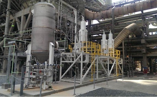
SAM LORDO (Nalco Champion)
The best place to manage at least calcium, sodium and iron are in the desalter, either the crude unit or FCCU pretreatment. Nalco Champion has two approaches, acidic and non-acidic, depending on the metal to be removed. Below is one example of a non-acidic iron removal program.
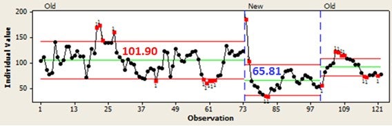
SHAUN SPIRO (XOS)
Metals found in tight oils greatly impact the performance of the FCC, as well as costs associated with replacing and protecting catalyst. Iron and calcium levels are generally high in tight oils, while nickel and vanadium concentrations can vary. The contaminants lead to increased coke and hydrogen formation with decreased gasoline production. The easiest method to control metal deactivation is to supplement with fresh catalyst, although this can be very expensive. Manufacturers have created catalysts to better handle specific metals (and combinations of metals) that are associated with tight oils. Metal trapping additives can be used to reduce the impact of metals (specifically V and Ni) and protect catalyst. Critical to improving performance is to accurately and quickly measure the metal concentrations in the FCC feed. Many of our customers utilize the XOS Maxine benchtop analyzer to measure critical metals in the FCC process. All the metal concentrations are given in a single 10-minute test as opposed to waiting hours for ICP (inductively coupled plasma) testing, which can be vital in determining unit performance or troubleshooting. The easy test and rapid results can free up laboratory resources for other analysis.
RALPH WAGNER (Dorf Ketal)
We understand that there is a concern of FCC catalyst deactivation due to the presence of metals in tight oil feedstock resulting in substantial cost on fresh catalyst. Key metals that are present in the FCCU feed are calcium, sodium, iron, magnesium, nickel, and vanadium. Calcium, sodium, and magnesium content can be reduced by optimizing the crude desalter and, in the case of resid feed, incorporating the desalter upstream of the FCCU.
The standard desalting process does not remove oil soluble compounds such as calcium naphthenate, iron naphthenate, and other metals present in organic form. Water insoluble compounds such as iron oxide, iron sulfide, and silica also present processing challenges.
Metal removal additives are available to enhance metal removal in the desalter. Selection of the best additive is a function of water chemistry, metals present, wastewater limitations, and downstream process configuration. Most options are acidic, but there are also non-acid options.
RYAN NICKELL (Albemarle Corporation)
Several steps should be taken to ensure optimal profitability and stability from an FCC unit receiving tight oil fractions. The metal contaminants in tight oils can vary significantly, not only from one shale play to another but also within a given play over time. A full analytical analysis of the feed will allow the catalyst provider to make optimal technology and formulation decisions. Some tight oils are very high in Na (sodium); therefore, optimal operation of available desalter capacity is advised. The most important step is, perhaps, selection of a catalyst specifically designed for tight oil feeds. Albemarle offers AMBER™ T, UPGRADER™ T, and ACTION™ T which are demonstrating tangible benefits for refiners.16,17 Though tight oils are very light (high API, low CCR), they are often mixed with heavier feeds to better fit refinery design. UPGRADER™ T fits these heavy feed applications while AMBER T is the choice for lighter feeds. When the paraffinic nature of tight oil affects the FCC naphtha octane, ACTION is the preferred catalyst family proven in over 10 FCC units within North America. ACTION™ T contains ADZT-100, a proprietary zeolite technology that promotes octane enhancement and butylene production. A key feature of all three aforementioned catalyst families is their use of Albemarle’s matrix technologies which provide high resistance to the “new” metals in question, as well as conventional ones. Fe and Ca from tight oils are particularly detrimental since they interact synergistically to form an impenetrable skin on the catalyst surface. This phenomenon effectively deactivates all interior acid sites that help facilitate the cracking reactions. Albemarle’s tight oil catalysts have exceptional surface and pore accessibility; thus, they resist iron and calcium better than competing technologies. Finally, the light FCC feed resulting from tight oils can lead a refiner to be short on delta coke and low on regenerator temperature. In this case, the Best Practice will further depend on the individual FCC unit design and constraints. Albemarle may recommend an adjustment to the activity, nickel-tolerant matrix, or use of antimony. These considerations are optimally addressed with an Albemarle representative.
Year
2015
Process