
Petrochemical Industry Experts Showcase – The State of the Petrochemical Industry
Petrochemicals power the global economy with the many lifesaving and life-improving products they make possible. The demand for petrochemicals is expected to grow both considerably and rapidly as the global middle class continues to expand. Despite this, growth in the petrochemical industry faces headwinds and challenges, including supply chain issues, new domestic and international policies, and changing market dynamics.
This session will showcase leading experts’ thoughts on the current state of the petrochemical industry and the future of our industry. Specifically, four consulting and analysis firms will provide their commentary on various aspects of the petrochemical industry.
Question 39: What operating conditions increase the generation of coke fines? What reliability issues do you associate with increased fines production?
BILL CATES (Hunt Refining)
Coke fine generation is really a function of the coke cutting process. Feed stock and coke drum operations during the actual drum fill cycle have very little to nothing to do with the generation of coke fines.
Coke fines are formed during the drilling of the pilot hole and during the cutting cycle due to the grinding nature of these two tasks. In each case, the longer it takes to cut the pilot hole and then to cut the coke will lead to additional production of coke fines.
The main issue with the coke fines is the particle size. The smaller the fine, the longer it will take for the fine to settle. This leads to increased fines in the clean water tank which will settle and over time form a substantial layer of solids in the bottom of the tank. Using a snorkel style of pump to try to remove these fines is the normal means of solid removal. The issue is that the snorkel needs to me moved periodically which can stir up the small particles. When this happens, the cutting water now will contain particles which over time will erode the internals of the jet pump or the cutting head nozzles.
In our experience, we have had to bring in outside equipment to help to remove the solids out of the bottom of the clear water tank. This is done at a large expense as equipment like a filter press is used to get the small particles out of the tank. Once removed from the tank, the filter cake is analyzed for “purity” meaning that if the filter cake does not contain rocks or trash then the cake is put back on the coke pad to be sold along with the coke. If the filter cake contains too much foreign material, it will be disposed of in an approved landfill facility.
MICHAEL KIMBRELL (Becht Engineering)
Soft coke produces coke fines. One method of making soft coke is by operating at low drum temperatures. Another method is to add FCC slurry oil to the feed and not increase the heater outlet temperatures. Some paraffinic feeds require more energy per bbl of feed to convert completely to coke and they will make sandy coke or a soft coke that will cause the quantity of fines to increase. Not filling the coke drums to the minimum outage will result in a higher percentage of coke fines. This is due to the top portion of the coke pile being softer than the rest of the coke pile. At high outages, that soft portion is a higher percentage of the total coke produced.
The technique used to cut coke out of the coke drum and the condition of the cutting equipment is another way to impact the generation of coke fines. If the cutting equipment is worn and the cutting nozzles do not generate a sharp stream of water to the coke bed, the momentum is spread out over more of the coke surface which removes small pieces of coke rather than cutting out larger chunks. The drill stem speed of rotation and the rate of vertical travel are other variables that can impact the total quantity of fines generated.
EZEQUIEL VINCENT (KBC)
Generally, coke fines tend to be generated in a low temperature, high pressure operation, and from crude mixtures where one crude has high asphaltenes while the other crude has very low asphaltenes content (e.g., WTI and WCS).
Coke fines pose concerns with environmental pollution due to high dust generation; they also affect the cutting water equipment reliability.
Coker fines are produced during the process of cutting the coke out of the Coker drum and are recirculated through the jet nozzles via the cutting water (which is recycled). The fines can also be created when the high-pressure water “smashes” the coke, rather than cutting it, liberating fines large enough to cause issues, but small enough to pass through the fines filtration system in the cutting water. The smashing of coke is a result of eroded drill bit nozzles due to coke fines in the cutting water.
Question 40: What is your experience, design and opportunities for on-line crude blending coupled with near infra-red?
Question 41: What effective practices do you deploy to improve the removal of inorganic contaminants in crude such as iron and calcium? What has been the industry success rate with these practices?
BRANDON PAYNE (SUEZ Water Technologies & Solutions)
Cracked feedstocks can be introduced into the crude unit from several sources; the most common of which in North America are diluted bitumen from Canadian sources, diluted crude oils from South American sources, and slop streams from cracking units onsite that are recycled into the reprocessed slop oil blended into the crude unit feedstream. Asset operators have experienced unanticipated issues due to the reactive nature of these cracked stream components in previously unanticipated areas of the unit.
Fouling in the crude unit preheat train and the fouling of distillation column sections are common consequences of the introduction of cracked stocks in the unit feed. Due to the nature of the contaminant (i.e., recoverable hydrocarbon), adjustments in desalting practices will not remove or affect the behavior of these materials in the preheat train or distillation column. Additionally, traditional crude preheat antifoulant treatment chemistries are generally designed to disperse precipitated particulates, not address the polymerization issues associated with cracked materials. Depending on the boiling range of the cracked stocks, fouling could occur in sections of the distillation column where fouling had not previously been a concern. However, there are several practices that can be implemented that will aid in the mitigation of these potential issues when the need to process cracked hydrocarbon feedstocks arises.
The first suggested mitigation is the segregation of cracked material whenever possible. The ability to tightly control the introduction of this material to the unit is critical in managing its detrimental effects in unit equipment. If complete segregation is not reasonably achievable, the second suggested mitigation is to minimize the volume of reprocess (“slop”) material that will be contaminated with the cracked stocks. (It will prove to be a significantly more manageable issue to deal with 3,000 barrels of contaminated material than 75,000 barrels of contaminated material.) A third suggested mitigation is the routing of cracked stocks to an appropriate secondary processing unit instead of routing to the crude slop oil system. This will minimize the unintended fouling of the crude unit equipment. A fourth suggested mitigation is the implementation of a robust antifoulant treatment program that will address potential polymerization issues resulting from the processing of cracked materials. If an antifoulant chemical treatment program is in place, ensure that the treatment protocol addresses the polymerization potential and monitor accordingly.
DENNIS HAYNES and CHRISTIAN LEEDLE (Nalco Champion)
There have been successful applications in the desalting process to remove iron and calcium to varying extents. The ability to remove either of these contaminants depends upon their form. Some methods of removal may include pH suppression of the desalter wash water, elevated wash water rates and optimization of mud wash practices, application of solids wetting chemistries, and may also include, in some limited cases, extraction of a portion of interface has been used to minimize iron and calcium containing solids. The method used depends on the element being removed (iron or calcium), the form it is in, and the amount that is targeted for removal. Generally, for calcium (in the form of calcium naphthenates), the removal rate may be as high as 80-90%. For iron, the removal rate varies depending on the technology applied; it may be 20-50% in some cases, but with enhanced methods may be as high as 90%.
Question 43: What are your economic and operational reliability implications of increasing cycles of concentration in your cooling tower?
LANCE COX (NALCO)
The benefits of increasing the cycles of an open-recirculating cooling tower include cost reductions for:
-
Water - Purchased and Waste treatment.
-
Chemical Treatment – Raw Water Clarification and Waste Treatment
-
Electrical Costs – Pump Requirements
-
Capital Cost Deferral – Plant Capacity Expansion via Utilities Optimization vs. Replacement
-
Plant Infrastructure Spending – Minimize Maintenance Spend on Existing Caused by Capacity Limitations or Reliability Issues (i.e., Piping with Reduced Volumetric Capacity)
Operationally, especially as production units are debottlenecked over time, increasing tower cycles could facilitate the ability to utilize existing Utilities Infrastructure. This minimizes the need to undergo a disruptive engineering and installation processes should unit capacity enhancement projects be identified. This also aids in speeding those projects to fruition.
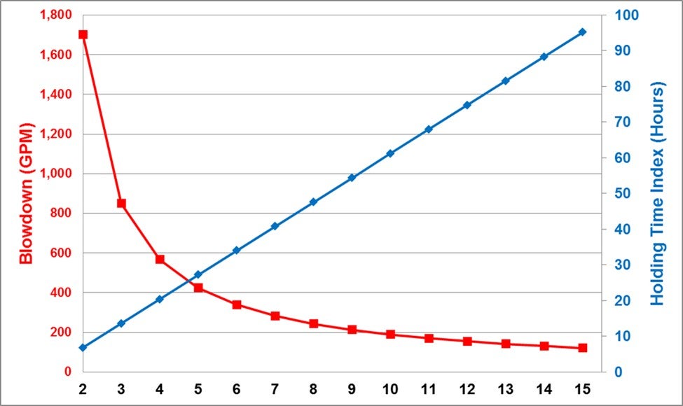
Certain reliability implications will be experienced to varying degrees. Increased cycles will impact the Water Quality, which can impact each heat exchanger in the circuit. A higher ionic species in the water will need to be evaluated from various aspects, including corrosivity, scaling and emissions (Air - PM10/2.5 and Receiving Bay TDS Regulations). The advent of enhanced treatment chemistries has broadened the acceptable operating window of these systems, while preserving performance capabilities. That said, the impact upon emissions should always be observed along with the diminishing returns as cycles increase. The non-linear characteristic of cycles vs. blowdown rate shows the sharp decline as cycles increase beyond the 5 to 8 level, while the Holding Time Index (HTI) increases steadily. (See Figure) HTI is one stress which becomes evident with respect to the treatment chemistries and crystal development characteristics, potentially leading to mineral scale deposition. The percentage of make-up water flow blown down from the cooling tower can be calculated by taking inverse of the cycles level. This states that the % of the tower make-up flow blown down will DECREASE from 20% (5 Cycles) to 10% (10 Cycles).
Reliability is only partially determined by Water Quality. The design characteristics of the exchanger circuit and individual exchangers are critical. Stress factor impact on heat exchange surfaces, such as Skin Temperature, Flow Velocity and Heat Flux will be exacerbated by a change in Water Quality. Each exchanger should be evaluated with respect to its design and how the water is changing. This analysis could require adjusted control strategies, including different limits, chemical treatment products, and possibly tighter control expectations. A thorough analysis of the various Mechanical, Operational and Chemical aspects of the system should be included in the decision to increase cooling tower cycles.
Question 44: Describe your procedures for placing and operating the FCC in hot standby/safe park mode. What safety concerns do you consider and what safeguards should be in place?
ALEC KLINGHOFFER (Coffeyville Resources)
The first question you should ask when considering what "safe park" mode means would be is the air blower running or not?
If the air blower is not running, things you should consider are ensuring all ignition sources are shutdown, bypassed or isolated (ESP, torch oil, DFAH, CO Boiler). Verify all hydrocarbon sources to the reactor, riser and regenerator are closed (fresh feed, any recycles, torch oil, fuel gas purges, LCO quench, etc.) and all sources of air are not being injected (main air, plant instrument air, fluffing air, etc.). Consider isolating by blocking in, DBB or blind as a stabilizing action. Confirm slide valves are closed and maintaining a positive ΔP (3-5+ psig). Close fuel gas to furnaces unless feed or fractionator bottoms oil circulation is maintained. Confirm you have steam to air blower(s) discharge, feed riser, feed & torch oil nozzles. Verify steam purging of reactor to the fractionator is controlling the reactor pressure greater than the fractionator and greater than the regenerator by 2+psi. Verify steam to MAB discharge is being injected at the prescribed rate. Verify steam to feed nozzles matches design curve specification. *If steam is not available, then use nitrogen (very large volumes of nitrogen will be required for cooling, due to its very low heat capacity). If neither steam, nor site nitrogen are available, then source a contract nitrogen vaporizer as soon as practical. Verify that the MAB discharge line is clear, and that MAB check valve has closed. Check status of Wet Gas Compressor (WGC) — in some units the WGC auto trips on blower shutdown, the reactor pressure must be higher than the fractionator and the regenerator to prevent flow reversal. If unit has a power recovery turbine, ensure that flue gas quench system is preventing the PRT inlet temperatures from exceeding limits. The vapor spaces of the regenerator and flue gas system must be purged before restarting the MAB. Use N2 or steam in enough quantities for 3 volume changes from the purge point to the stack. Sample gas in regenerator and flue gas system for combustibles. Ensure steam is dry, preferably superheated. Oil soaked on catalyst will crack to form explosive gases. In addition, steam passing through catalyst at temperatures above 1000°F will make HYDROGEN and CO via the water gas shift reaction. When purge is complete, and gases are verified to be free of combustibles, air can be introduced to the unit and catalyst circulation restarted. This must be done as SLOWLY as possible. Temperatures must be monitored to ensure no rapid rises. If there are rapid temperature rises, must go back and repeat purge and combustible check.
MINAZ MAKHANIA (UOP)
If the air blower is running, confirmation feed has been bypassed with isolation valves closed, again DBB or blind as a stabilizing action. De-energize ESP. ESP should not be re-energized until the flue gas has been verified to contain no combustibles and is below the acceptable CO levels. Nitrogen or steam to Riser at rates adequate to keep Reactor as high-pressure point (Reactor>Main Fractionator and Regenerator). Set Reactor at the highest pressure in the system. We specify pressure differential because required flow rates will be different under varied conditions. Pressure conditions are constant under all scenarios. Steam to feed nozzles at design curve specification (feed nozzles are very prone to plugging in the posture). Monitor vessel velocities to prevent exceeding velocity and temperature limits. Confirm slide valves are closed and maintaining a positive ΔP (3-5+ psig). Main Fractionator to steam pressure control. Use torch oil to control regenerator temperature. Maintain levels in Main Fractionator and GRU. Conduct extensive catalyst loss monitoring.
TIFFANY CLARK (BASF)
Standby #3, in a situation where the air blower is running, and catalyst circulation is being maintained, this can be a difficult operation to control long term and has significant risk associated. A big risk being detonation of ESPs that has occurred in the industry.
Major things to consider in this mode of operation to ensure safety are:
De-energizing ESPs until stable operation is reached, and monitoring the flue gas system upstream of the ESP regularly for hydrocarbon and CO.
While circulating catalyst, you should always maintain isolation between the Regenerator and Reactor/Main Fractionator by pressure balance.
And then, while most ESD systems will trip the feed isolation valves closed for you, you should always verify feed has been bypassed and that the isolation valves are closed and not leaking by.
Other things to verify include that you have adequate oil flow through Main Fractionator bottoms system so as not to build up catalyst. A sufficient level in the Main Fractionator should be maintained at all with adequate flush to tankage.
Nitrogen or steam to riser/stripper should be maintained at rates adequate to hold Reactor pressure as the highest pressure in the system by at least 2+psi. You should closely monitor the Reactor-Regenerator pressure balance, fluidization and catalyst circulation stability to prevent oxygen from entering the Reactor. The Main Fractionator should be on steam or nitrogen pressure control and adequate steam to the feed nozzles is required to prevent plugging the nozzles and should be consistent with design specifications.
You also want to monitor velocities and catalyst levels to prevent excessive catalyst carryover during this mode of operation. Monitor your slurry ash content and Regen fines or Scrubber solids content frequently and conduct extensive catalyst loss monitoring.
While torch oil is being used to maintain Regenerator temperature, it should be monitored very closely to prevent exceeding temperature design limitations and significant catalyst de-activation. You should adjust catalyst circulation rates to prevent temperature excursions or excessive thermal cycles in Reactor. The Main Fractionator overhead system should be monitored routinely for excessive oxygen buildup and steam condensate acidity. Also, maintaining levels in the VRU will help tremendously on unit startup.
Question 45: What are the safe and reliable options for rodding out plugged bleeders such as hydraulic ram pumps, packing gland / drill assemblies or tangential bleeders? How are these options used in a best practice for ensuring piping is hydrocarbon free and ready for maintenance?
CASEY LANG (MERRICK & Co.)
Rod out tools or bleeder cleaners are safe and effective at clearing clogged drain, vent and instrument valves to be cleaned during normal operations. Most include some type of drill bit and local pressure gauge and are designed to handle high temperature and pressure applications. Packing material should be selected based on stream corrosivity, pH and pressure requirements. Several arrangements are available direct from manufactures, for example: Straight, Flexible, 90º, 135º.
Reliability Guidelines:
-
Ensure annual leak test and hydrotests are documented.
-
Verify design Temperature, Pressure, packing material for intended service.
-
Maintain tool functionality (i.e., sharp drill bit, valve integrity, threaded connections)
Safe Use Guidelines:
-
Ensure drill bit has been fully retracted with measurements and markings before closing process valve.
-
The handle and drill bit should ONLY be turned to the right (clockwise) to prevent ‘unwinding’ during insertion and retraction.
-
Do not flow process fluid through device; Temperature and Pressure rating based on zero process flow.
-
Always remove tool after use, not intended as permanent drain valve.
Manual hydraulic ram pumps have also been successfully employed at Refineries. Diesel type product is pumped directly through the (bleeder) valve using a portable PD pump.
Main column bottoms and HCO circuits are most prone to pugged drain and vent valves.
ALEC KLINGHOFFER (Coffeyville Resources)
Bleeders and taps are cleaned out using a tool like the one shown in the picture. The tool is attached to the bleeder and the obstruction is drilled out. The apparatus is contained, and line pressure can be vented. These tools are available from several different vendors.
DEWEY STUART (Motiva Enterprises)
The primary tool used for plugged bleeders are packing gland/hand drill assemblies. These tools come with a pressure gauge to verify if the bleeder is unplugged. Choosing the correct assembly for both connections and system pressures is critical to prevent releases while also clearing the bleeder. The packing gland rating and current condition needs to be verified and checked for each connection location.
We also use Multi-Pressure Bucket Pumps and on occasion, primarily used for instrument taps, is a small, fixed volume nitrogen container.