Toledo Rally Spotlights RFS Threat to Refineries
Video Media
WARDINSKY (ConocoPhillips)
We do not have any current FCC projects that plan on utilizing some form of CO2 offset or credit in the emissions analysis. ConocoPhillips has performed a limited modeling study to evaluate the effect of operational changes on CO2 emissions from the FCC. Also, the study indicated that there is very little you can do to reduce overall emissions without also overall significantly reducing unit throughput or conversion. One obvious adjustment is to increase feed preheat to reduce coke yield and get back conversion by increasing equilibrium catalyst activity. However, the increased CO2 emissions from the feed heater nearly offset the reduced CO2 emissions from the regenerator flue gas stack. FCC energy efficiency improvement projects that we have been implementing recently within ConocoPhillips include replacement of steam turbines with electric motors and optimization of feed preheat furnaces. Other opportunities to improve FCC energy efficiency include recommissioning out-of-service flue gas expanders and increasing heat integration between the main fractionator and gas plant reboilers.
As an informational note: In the 1980s, Air Products reported on an FCC process utilizing O2 enrichment for coke combustion with CO2 recycle and sequestration. This process presents several technical and economic challenges to FCC operations.
HEATER (BASF Catalysts)
As Mike mentioned, it is important to remember that the FCC runs in heat balance. All the heat needed to run the process will eventually come out as CO2 either in the flue gas, the CO boiler or the feed heater. Two main sources of CO2 generation are from the combustion of coke and from the CO boiler/feed preheater stack gas. Optimum design of the CO boiler and feed heater burners can mitigate CO2 production. CO2 from the flue gas, when looked at in the big picture, is very minor compared to the CO2 generated from the fuel produced by the FCC; for example, gasoline and diesel fuel. When in petrochemical mode (C3s and C4s are going to petrochemical market), that CO is reduced. Likewise, when slurry goes to carbon black, that CO2 is reduced.
WARDINSKY (ConocoPhillips)
We have not benchmarked particulate removal technologies within our system for PM 2.5 removal. This data is difficult to obtain because many stack tests do not analyze the captured particulate matter for particle size distribution or PSD. To calculate the particle size or grade removal efficiency, the PM mass rate and PSD need to be obtained upstream of the removal equipment, as well as downstream. It is important to understand the mechanism of catalyst attrition in FCC units when evaluating PM removal technologies. We have been able to decrease PM emissions by up to 0.2 lbs/1000 lbs of coke burned by changing catalysts. Scanning electron microscopy, imaging of fresh catalyst, and e-cat can be useful tools in understanding catalyst attrition mechanisms. In addition to installing equipment for PM removal, it may also be necessary to modify the regenerator and regenerator internals. Additional regenerator vessels height to reduce catalyst entrainment, replacing regenerator cyclones, and replacing the air distributor are all steps that ConocoPhillips has taken to reduce PM emissions.
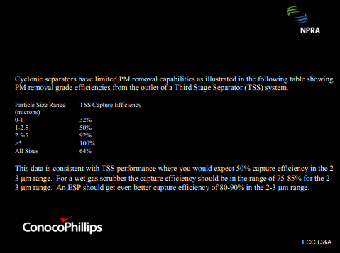
Cyclonic separators have limited PM removal capabilities, as illustrated in this table showing the PM removal grade efficiencies from the outlet of a third-stage separator system. As you can see, this data is consistent with TSS performance where you would expect about a 50% capture in the 2 to 3 micron range. For a scrubber system or an ESP, you would expect considerably higher grade capture efficiencies.
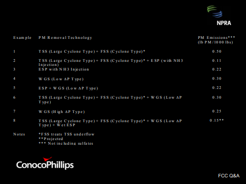
This table illustrates some of the PM removal capabilities of different technologies. We have different combinations and permutations of technologies within our system. These are reported in terms of pounds of particulate matter per thousand pounds of coke burned or a MAC2-type number. ConocoPhillips is going to be installing a wet gas scrubber with a wet ESP at one of our sites to reduce the PM and SO2 emissions in order to meet local PM emissions limits. I think this table is interesting because it shows some of the effects of having a third-stage separator up front of a dedicated PM removal technology, as well as some of the combinations we see within our system.
HEATER (BASF Catalysts)
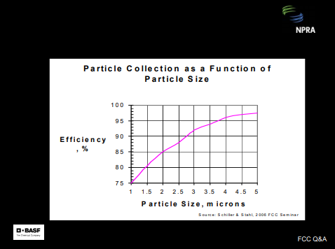
It is difficult to achieve greater than 50% PM2.5 reduction with conventional third- and fourth-stage separation systems. However, most ceramic and centered-metal filters have shown good success in significantly increasing capture efficiency. Flue gas scrubbers will often achieve greater than 95% reduction over a four-year run. BASF Catalyst believes that this is an area requiring further development and they have devoted significant resources in that direction. ESP particulate removal was covered in an excellent paper by Shiller and Stahl from the 2006 FCC Seminar. Their data shows an 85% to 90% reduction of the PM2.5 with a well-designed and operated ESP.
YE-MON CHEN (Shell Oil Company)
I have a comment on the separation efficiency on the third-stage separator. In the past, in the third-stage separator, the cutpoint—meaning the 50% capture—is around the 2.5. The new generation of the third-stage separator technology can achieve a cutpoint of about 2 microns.