
Question 42: What options are available to produce on-spec jet fuel from high total acid number (TAN) sources? What impacts these choices?
PIZZINI (Phillips 66)
Regarding the conventional hydrotreating, I do not think high TAN would be an issue; but if you try to caustic-treat high TAN material, you will end up with what amounts to be the equivalent of lye soap. So anywhere you want oil and water separation to take place, the soap components may cause rag layers and carryover. We have to employ periodic waterwashes of
solid bed processes or sufficient purge and makeup water to prevent the buildup of the soaps before they cause separation issues.
KOONTZ (HollyFrontier)
Four out of five HollyFrontier refineries treat the kerosene fraction in a hydrotreater, so the TAN of the crude does not matter. The fifth, our Tulsa refinery, does utilize the Merox process to produce jet fuel. However, the crude to this unit is relatively sweet. The kerosene fraction averages 0.002 mg (milligram) of KOH per gram of kerosene and has ranged as high as 0.06; but at these low TANs, they have not experienced problems.
NATHAN KEEN (Merichem Company)
The naphthenic acids that produce stable emulsions, to which this discussion refers, tend to concentrate up in the jet fuel and diesel cuts. Merichem has developed the NAPFINING™ HiTAN technology that treats the kerosene and diesel fractions. Merichem considers any jet fuel or kerosene feed with 0.1 TAN or above as high TAN. To date, Merichem has customers who have successfully processed jet fuel fractions above 1.0 TAN in commercial units without getting the uncontrollable rag layers to which you are referring.
KOONTZ (HollyFrontier Corporation)
HollyFrontier processes crude primarily from Texas, Canada and the Mid-Continent. Of these, certain heavy and synthetic crudes from Canada have the highest TANs. Four of the five HF refineries utilize hydrotreating to desulfurize the kerosene fraction and have not noted a significant jet/kero (kerosene) impact from processing these high TAN crudes. The HF Tulsa refinery utilizes the Merox process to produce jet fuel. The crude input to this refinery is relatively sweet. The kerosene fraction averages ~0.002 mg KOH/g kerosene, but has ranged as high as 0.060 mg KOH/g kerosene. At these low TANs, they have not experienced problems maintaining acceptable jet quality.
Year
2012
Process

Question 43: In reforming units, what equipment could be susceptible to high temperature hydrogen attack (HTHA)? How are panelists approaching evaluation and replacement of equipment that could be susceptible to HTHA?
KOONTZ (HollyFrontier)
First, a little background: API 941 discusses high temperature hydrogen attack. At low temperatures, less than about 430°F, carbon steel has been used successfully up to 10,000 psi. But with elevated temperatures, the molecular hydrogen will dissociate into atomic hydrogen, which can readily enter and diffuse into the steel. The hydrogen reacts with the carbide in the steel to form methane, which is trapped inside the steel and will eventually form a crack or blister. The addition of carbide stabilizers to the steels – such as chromium, molybdenum, tungsten, and vanadium – can resist the decarburization reaction within the steel.
Beginning in the 1940s, G.A. Nelson collected and published empirical curve data to demonstrate the conditions at which high temperature hydrogen attack is expected for specific metallurgy and operating conditions. These data are known as the Nelson Curves and have been continuously updated over the years to include additional failures due to HTHA. The Nelson chart originally included a curve for carbon-0.5 moly (molybdenum), which was midway between the carbon steel curve and the 0.25 chrome-0.5 moly curve. Ever since 1970, a series of unfavorable service experiences with carbon-0.5 moly steels have reduced confidence in the position of its curve on the chart. Data indicate that how the metal is fabricated does have a strong correlation to its susceptibility to HTHA. In 1990, API removed the carbon-0.5 moly curve completely from the Nelson chart.
HollyFrontier generally uses the carbon steel curve on the Nelson chart to evaluate carbon-half moly steels in its process units. Some process equipment has utilized stainless steel cladding or weld overlay to mitigate the concern with HTHA of the base metal. However, this does not completely eliminate the risk. Hydrogen will still diffuse through the cladding and affect the base metal. The partial pressure of the hydrogen at the base metal will be lower than without the cladding, but it must be carefully evaluated to assure that HTHA would not be expected. Real-world experiences have also demonstrated that no cladding or weld overlay is perfect. It only takes one small imperfection for the hydrogen to find the base metal and attack it. API says that it is not advisable to take credit for the presence of a stainless-steel cladding overlay when selecting the base metal for a new vessel.
HollyFrontier has performed a full review of its process units to identify the risk for HTHA, especially for carbon-0.5 moly steels. The review indicated concerns in the reaction section of some of the units. The general strategy for HollyFrontier for carbon-0.5 moly steel operating above the carbon steel Nelson Curve is to remove it from service. If the carbon-0.5
moly steel is clad or overlaid with 300 series stainless steel, a Fitness for Service Evaluation is performed to ensure that the equipment is safe for operation.
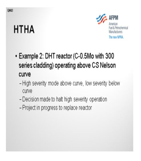
One example is of a naphtha hydrotreater that was operating slightly above the carbon steel Nelson Curves. Based on a detailed analysis of the cladding, it was deemed acceptable for continued operation. We are, though, in the process of a project to replace that reactor.
In another example, a kerosene hydrotreater operates in two distinct regimes. It makes ULSK (ultra-low sulfur kerosene) part of the time and jet the rest of the time. While operating in the jet regime, the operating point is below the carbon steel Nelson Curve and is, therefore, not a problem. However, when we operated in the high severity mode, it did go above the carbon steel curve. Since the analysis was performed, we no longer run the high severity operation, and there is a project underway to replace that reactor.
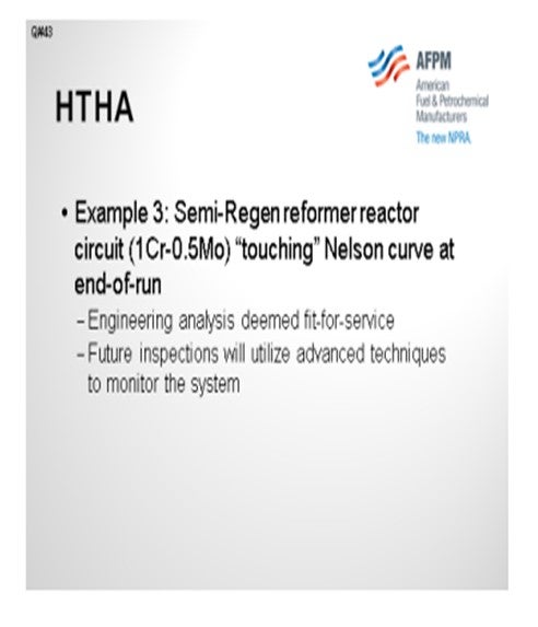
The original question asked about reformers. Older semi-regen reformers are especially of concern since they operate at much higher hydrogen partial pressure than does a modern CCR. HollyFrontier operates two semi-regen reformers in El Dorado and Woods Cross. These reformers have unusually high reactor pressures for reducing coking. Of course, there is concern about both the feed effluent and the reactor circuits. The review did not indicate any carbon-0.5 moly steel in the reformers. However, in one case, it was found that at end-of-run conditions, the operating points were touching the 1.0 chrome-0.5 moly curve for a particular vessel. Historical data was used to determine how much time had been spent touching the “curve.” This data was then used to perform a detailed Fitness for Service Evaluation, and the reactor was deemed “fit for service”. Future inspections will utilize advanced nondestructive evaluation (NDE) on these areas to increase our confidence that HTHA is not impacting the integrity of the vessel.
KOONTZ (HollyFrontier Corporation)
High temperature hydrogen attack (HTHA) is discussed extensively in API Recommended Practice 941. At low temperatures (less than ~430ºF), carbon steel has been used successfully at pressures up to 10,000 psi. However, at elevated temperatures, molecular hydrogen will dissociate into atomic hydrogen which can readily enter and diffuse through steel. The hydrogen reacts with the carbide in the steel to form methane, a process termed decarburization. The methane is too large to diffuse out of the steel and eventually the internal pressure is high enough to cause a blister or fissure in the steel. These cracks eventually result in a significant deterioration of mechanical properties which can cause a loss of containment. The addition of carbide stabilizers to the steel such as chromium, molybdenum, tungsten, vanadium
and titanium resist the decarburization reaction within the steel.
G.A. Nelson collected and published empirical data for API beginning in the 1940s to demonstrate the conditions at which HTHA is expected for specific metallurgy and operating conditions (temperature and hydrogen partial pressure). These data are known as the Nelson curves and have been continually updated over the years to include additional failures due to HTHA. The Nelson chart originally included a curve for C-0.5 Mo (carbon-0.5 moly) that was midway between the CS (carbon steel) curve and the 1.25 Cr (chrome)-0.5 Mo curve. Since1970, a series of unfavorable service experiences with C-0.5 Mo steels has reduced confidence in the position of its curve on the chart. Data indicate that how the metal is fabricated has a strong correlation to its susceptibility to HTHA. In 1990, API removed the C-0.5 Mo curve completely from the Nelson chart. HollyFrontier generally uses the CS curve on the Nelson chart to evaluate C-0.5 Mo steel in its process units.
Some process equipment has utilized stainless steel cladding or weld overlay to mitigate the concern with HTHA of the base metal. However, this does not eliminate the risk completely. Hydrogen will still diffuse through the cladding and affect the base metal. The partial pressure of hydrogen at the base metal will be lower than without the cladding, but it must be carefully evaluated to assure that HTHA would not be expected. Real world experience has also demonstrated that no cladding or weld overlay is perfect; it just takes one small imperfection in the cladding/overlay to allow full hydrogen pressure to impact the base metal. Furthermore, inspection of the base metal is difficult as it is hard to find the damage below the cladding/overlay before enough damage has been done to decrease the mechanical strength. API says that it is not advisable to take credit for the presence of a stainless-steel cladding/overlay when selecting the base metal for a new vessel (i.e., overlay/cladding would be used to resist other corrosion attacks, but not HTHA).
HF has performed a full review of its process units to identify risks for HTHA (especially for C-0.5 Mo steel). The review indicated concerns in the reaction section of some of the units. The general strategy of HF for C-0.5 Mo steel operating above the CS Nelson curve is to remove it from service. If the C-0.5 Mo steel is clad overlaid with 300 series stainless, a fitness-for-service evaluation is performed to ensure that the equipment is safe for operation. In one example, a naphtha hydrotreater is operating slightly above the CS Nelson curve. Based on a detailed analysis of the cladding it was deemed acceptable to continue operation. However, HF is in the process of replacing the reactor and part of the feed/effluent circuit to assure long term reliability.
In another example, a kerosene hydrotreater operates in two distinct regimes when its product switches between jet and ULSK/ULSD (ultra-low sulfur diesel). It is below the CS Nelson curve when producing jet, but it passes above the curve when producing product at 10 ppm sulfur. Since the HTHA analysis has been completed HF no longer runs the unit in high severity mode. A project is underway to restore the ability to operate in high severity mode. The original question asked about reformers. Older semi-regeneration reformers are especially of concern since they operate at much higher hydrogen partial pressures than a modern CCR. HF operates two semi-regeneration reformers in El Dorado and Woods Cross that have unusually high reactor pressures to reduce coking. Of course the main areas of concern are from
the feed/effluent exchanger(s) through the reactors and furnaces. The review did not indicate any C-0.5 Mo steel in HF reformers. However, in one case it was found that at end-of-run conditions the operating points were “touching” the 1 Cr-0.5 Mo Nelson curve. Historical data was used to determine how much time has been spent “touching” the curve. This data was used to perform a detailed fitness-for-service evaluation. Future inspection will utilize advanced NDE on these areas to increase confidence that HTHA is not impacting mechanical integrity.
Year
2012
Process
Sabine Lange Ph.D., DABT
Section Manager, Toxicology Division
Texas Commission on Environmental Quality

Question 44: How is coke on catalyst in fixed-bed and moving-bed reforming units tracked? How is this data used to adjust the reactor inlet temperatures in order to maintain constant product octane?
PIZZINI (Phillips 66)
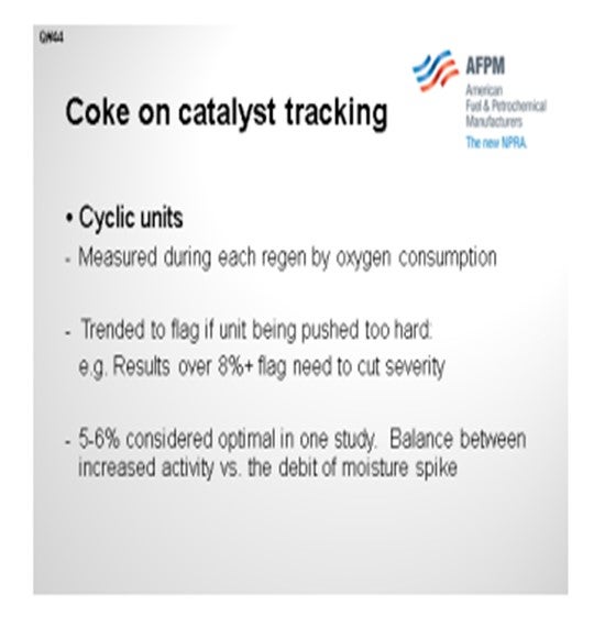
In our cyclic units, just based on the air consumption, we can measure the coke each time a reactor comes out for a regen. We are not grabbing samples. Our experience with the cyclics is that if you get up around 8% coke on catalyst, the unit will be pushed a little too hard. You will then need to think about backing it down on feed rate octane, finding a better-quality feed, or possibly increasing the hydrogen/oil ratio.
In one of our studies, we found that 5% to 6% coke on catalyst for a cyclic was just about optimal between the activity and the effect on yields. Every time we switch in a new reactor, we have a bump in moisture, resulting in more C4- until the unit dries out.
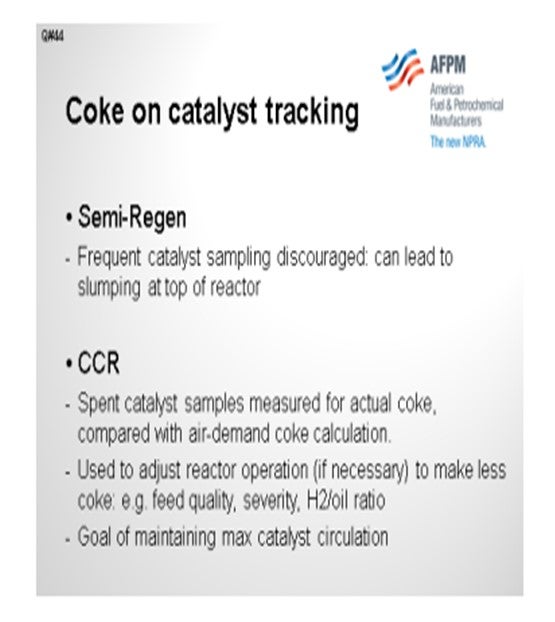
Where we could regen faster, we discovered that the optimum cycle was to allow 5% or 6% coke on catalyst. Some of our semi-regen vessels do have catalyst sampling options, but we actually discourage taking those samples frequently. The concern, of course, with a radial reactor is that you never want to uncover the top part because it could allow gases to bypass into the center downpipe.
The octane control on a semi-regen is just a matter of sending samples to the lab and tracking the octane. The purposes of the other components are to figure out the length of your run and manage feed rate and severity to make the run.
On CCRs, we do sample the spent catalyst directly for coke on catalyst. That number is compared with the calculated coke number, which is determined based on the air demand. Again, that number is used to track whether or not we are pushing the unit too hard. If it will be necessary to make less coke, then you could reduce the octane feed or increase the hydrogen-oil ratio. The goal is to maintain a maximum circulation of catalyst.
STEVES (Norton Engineering Consultants, Inc.)
My experience and comments are about a moving-bed reformer or CCR. We track coke in two ways. As Paul mentioned, we take a sample of the catalyst and measure the coke in the lab. We also then calculate, by oxygen balance, the coke in the regenerator that is being combusted. We do not use the coke results to adjust the operating conditions for octane, but we do use it to ensure that the amount of coke entering is within the coke burning capability of that
regenerator.
I have seen coke prediction spreadsheets used to estimate the coke being made on the catalyst when the regenerator section is taken out of service for maintenance or screen cleaning. With that spreadsheet tool, we evaluate multiple cases to determine the impact of feed rate octane and feed quality on the coke levels to ensure that the coke stays below the maximum target levels before the regenerator is returned to service.
PATRICK BULLEN (UOP, A Honeywell Company)
For CCRs, we recommend that you do weekly sampling of the coke in your unit’s local lab to make sure that you are at the right point for your calculations and that you then make adjustments as needed.
PIZZINI (Phillips 66)
On fixed-bed cyclic units, the coke on catalyst is quantified on each reactor when it cycles out for regeneration. This information is mainly used to identify if the unit is being pushed too hard with respect to rates, octane, and H2/oil ratio. Experience has shown that coke on catalyst greater than 8% may indicate a coke-imbalance which will require a rate cut to hold constant octane. A study on one of our cyclic reformers showed that a regeneration frequency that averaged 5% to 6% coke on catalyst provided the optimal yields and activity. For that unit, regenerating too often caused a drop in average C5+ and H2 yields due to the moisture spike that results when each reactor comes back into the process from regeneration. Otherwise, RITS are adjusted “as needed”, based on daily octane results.
On one of our CCRs, we measure actual coke on spent catalyst to validate the air-demand coke calculation. Both readings are used to adjust reactor operation if necessary to make less coke (e.g., feed quality, severity, feed rate, H2/oil ratio) with a goal of maintaining maximum catalyst circulation. Catalyst samples are also used for chloride adjustment.
On our semi-regeneration reformers, we discourage frequent catalyst samples to test for coke content because over time the loss of catalyst increases slump and causes bypassing at the top of the reactor. This can affect reactor performance and lead to catalyst fluidization and attrition.
SUBHASH SINGHAL (Kuwait National Petroleum Company)
In CCR units, the coke in spent catalyst is analyzed, and regenerator conditions are adjusted to achieve the target coke level in the regenerated catalyst. Constant octane is maintained by adjusting reactor temperature, preferably flat profile.
Process
Question 45: What is the maximum allowable limit for the iron content of a reforming catalyst? Is this limit the same for semi-regenerative and continuously-regenerative catalysts?
DUBIN (Axens North America)
We have seen that the maximum allowable iron on catalyst cannot be reduced to a simple number. Historically, about 3,000 wppm is the level at which we see yield start to suffer, but not every wppm of iron has the same impact on the unit. Iron deposited on the surface of the catalyst, usually from corrosion-related byproducts, tends to have less of an impact on the overall performance. Some units have tolerated quite a high level of iron as long as the iron stayed on the surface of the catalyst bead. However, if the iron is able to migrate into the center of the catalyst bead, then the quantity needed to hurt yields could be much less than the 3,000 wppm I noted earlier.
As the iron migrates, we see the larger iron species hindering redispersion during regeneration. The yield penalty seen from this loss of redispersion mirrors that of a decreased metallic function for a given octane. Higher inlet temperatures are needed to meet a given octane, and subsequent loss of reformate is observed.
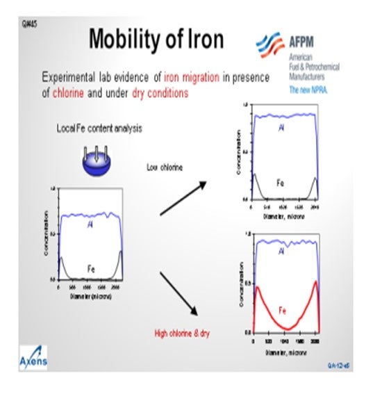
This slide shows a microprobe analysis of catalyst moving inward from the outer surface of the catalyst. You can see that the alumina is distributed uniformly throughout the catalyst particle. The iron concentrates on the outer surface of the bead, but we see that very little of it has migrated to the core. Under what we would consider low chlorine conditions, or sufficiently moist conditions, the migration of iron is mitigated. However, under higher chlorine content or drier reaction zones, the iron movement can increase and migrate into the center of the bead, leading to reduced yields. We consider a high chlorine environment to be 1.2 wt% to 1.3 wt% chloride on catalyst and dry being less than 10 wppm moisture in the recycle gas. Note that moisture tends to inhibit the migration of iron into the center of the bead.
Getting to the second aspect of the question about the allowable limit of iron on catalyst, we use the same limit on iron for fixed-bed and moving-bed reactors; however, the impact is not quite the same. For moving-bed reactors, the iron is distributed evenly across the catalyst due to the nature of the catalyst circulation, whereas in fixed-beds units, all of the iron deposit is in the first reactor. If the first reactor catalyst is sufficiently poisoned, the reforming reactions will move into the second reactor, and so on. However, it is difficult to play catch-up with the reforming reactions due to the endothermic nature of the reaction. Long term, it is hard to catch up on octane with a poisoned first reactor. For cyclic units, we have seen that the poisoning of the first reactor is essentially the same as a fixed-bed unit. However, with the swing reactor present, you have the ability to change out the first reactor catalyst if the catalyst underperforms
for whatever reason.
PIZZINI (Phillips 66)
It is really just a practical consideration regarding iron. We had a semi-regen unit that had to shut down, drop screen, and reload the first reactor without the benefit of a coke burn. We had removed most of the catalyst and were down to just the dust and fines. We then experienced a dust collector event on the vacuum truck. The dust contained pyrophoric iron since it had not been through a burn. In this case, the vacuum truck was set up with a nitrogen purge. However, the investigation showed that the truck did not have enough nitrogen purge. So just keep in mind that the iron can be pyrophoric, even on a reformer.
PATRICK BULLEN (UOP, A Honeywell Company)
UOP agrees with Axens that the situation is complicated.
DUBIN (Axens North America)
The maximum allowable iron content on catalyst cannot be reduced to a simple number. Historically, we have seen that at approximately 3,000 wppm, the impact on yields from iron starts to become significant. However, every ppm of iron on the catalyst is not equal in its effect on the unit. Often, iron that has deposited on the surface of the catalyst, typically from corrosion-related byproducts, has a limited impact on the overall performance of the catalyst. In several
instances, we have seen that the catalyst was able to tolerate high levels of iron while still performing at or near the expected level of conversion.
The quantity of iron needed to cause deterioration in the performance in certain circumstances can be well less than the 3,000 wppm mentioned earlier if the iron migrates to center of the bead from the outer surface. We have experience with a client who saw a decrease in performance at a lower content of iron on the catalyst. However, a significant portion of the iron in this situation had migrated to the center of the bead. As the iron migrates to the center of
the bead, platinum becomes less accessible as the larger iron molecules – e.g., FeS (iron sulfide)– plug the pores of the catalyst. The yield penalty observed during an iron poisoning situation mirror that of loss of metallic function. Higher average bed inlet temperatures would be required to compensate for the lost metallic function leading to decreased C5+ yields.
In Axens’ view, the iron contamination limit for semi-regeneration and continuously regenerative catalyst are the same, but the long-term operation with high iron catalyst is not. As the iron in the feed is distributed across the continuously regenerated catalyst evenly, the impact can be lessened or even delayed due to the catalyst circulation. For a semi-regeneration unit, the sulfur will accumulate on the first bed, potentially killing the activity of the first bed before the iron would theoretically migrate to the second bed; ‘theoretically’, because not many refiners would be able to maintain reformate production at an acceptable level with the long-term poisoning of the first reactor. Even moderate poisoning of the first bed in a semi-regeneration unit is a concern as it is unrealistic that a refiner can play ‘catch-up’ in subsequent reactors to meet the desired conversion due to the nature of the reforming reactions. Cyclic operations suffer from the same overall concerns as a semi-regeneration unit, but with a swing reactor present, the unit has the ability to replace catalyst on the fly when the yield penalty from poisoning is no longer acceptable.
PIZZINI (Phillips 66)
P66 also experienced a catalyst unloading issue related to pyrophoric iron on a lead reactor which had to be dropped and screened in an unburned condition. The presence of iron led to a vacuum truck dust collector event when vacuuming fines from the lead reactor. This was found to be the result of insufficient N2 purge on the vacuum truck.
Year
2012
Process