
Question 32: What is your suggested minimum temperature required to achieve adequate metals removal in the demetalization (demet) catalyst to protect primary treating catalyst in FCC and hydrocracker pretreaters?
TEMME (Albemarle Corporation)
The suggested minimum reactor temperature required for adequate metals removal is going to be metals specific. For silicon, the temperature is definitely greater than 570°F; and for nickel and vanadium, we suggest greater than 600°F. Now higher reactor temperatures may be required for adequate removal, depending on the space velocity through the metal-strapping catalyst and whether or not there may be a tolerance issue with the primary treating catalyst. It can also be very feed specific. If it is a very aromatic feed, such as a highly asphaltenic feed with high levels of porphyrin molecules, higher reactor temperatures may be needed to enable saturation of a ring(s) of the porphyrin structure to allow for the metal compound removal.
With very aromatic feed, close attention should be given to an optimal pore size of the metal-strapping catalyst with a larger pore-sized catalyst generally being needed. High nickel and vanadium content feeds require such a catalyst to avoid a premature form of plugging due to the metal deposition.
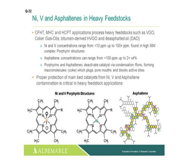
For hydrocracker pretreating's and other gas oil-types of processing applications, especially when processing heavy feedstocks, not only is nickel and vanadium problematic, but also the porphyrins and the asphaltenes. These molecules can deactivate the catalyst via a condensation reaction forming coke that is going to plug up pore mouths and block access to active sites. So proper protection of main bed catalysts for not only nickel and vanadium, but also for asphaltene contamination, is critical in heavy feedstock applications.
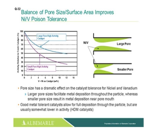
The left corner of this slide shows a comparison, in terms of large pore-sized catalysts versus small pore-sized catalysts, with the Y-axis showing the relative activity of the fresh catalyst as nickel and vanadium as deposited on the catalyst, which is the X-axis. You can see that the falloff and activity with the small-pore high activity catalyst can be much greater than that of the large-pore high activity catalyst. The graphic to the right really depicts this type of phenomenon where the larger pore catalyst allows for a fuller deposition of metal throughout the catalyst particle; whereas with the small pore-sized catalysts, there is pore-mouth plugging which restricts access to the active site. So, a good metal-tolerant catalyst is definitely needed for this full deposition of the metals through the catalyst particles. Now yes, there is usually some tradeoff in terms of a little lower activity; so, you definitely must have a good balance between your demet (demetallization) catalyst and your active catalyst to make sure that you have enough demet catalyst to protect your active catalyst.
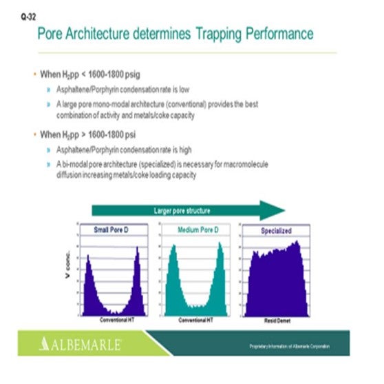
Just one other slide relating to asphaltene porphyrin condensation potential. The hydrogen partial pressure unit is below 1600 psig. A large-pore monomodal architecture type of catalyst, a conventional catalyst, is probably just fine for activity, as well as metals coke capacity. But for higher hydrogen partial pressure greater than 1600 where the condensation rates become higher, bimodal architecture specialized catalysts can be very helpful in terms of increasing the metals- and coke-loading capacity.
MORELAND (Valero Energy Corporation)
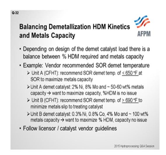
Thanks, Paul. That was a good summary. I told the guys at lunch today that we get a lot of the basics in this Q&A, and I think Paul covered really, really well the basic mechanisms in nickel vanadium plugging. So I will just bring a question to the audience describing a scenario I have seen while helping support our units within Valero. Some recommendations from our catalyst partners are a little different. We have two cat feed hydrotreaters – and this is for you experts in the room – that have two different recommended minimum temperatures for demetallization. Basically, this question asked about cat feed hydrotreaters and hydrocracker pretreats. Unit A is a cat feed hydrotreater for which our vendor recommended the demet temperature should stay below 650°F at start-of-run. I have a very similar unit in another one of our refineries. A different catalyst vendor recommended the start-of-run demetallization temperature be greater than 690°F. So, in one case, they say less than 650°F; and in the other, greater than 690°F. As I reviewed this issue more in-depth, I looked into the catalyst properties themselves. What we have found was that in Unit A, the catalyst itself that they were using in the demet beds was 2% nickel, 8% moly, and an expected 50 to 60 wt% (weight percent) metals pickup. So, my theory – and correct me if I am wrong – is that our goal here is to maximize the capacity of this demet catalyst. We are not really worried about the percent of nickel-vanadium removal. The second unit: You can see that the metals here were basically about half of what they were in the other. We are looking for almost twice the weight percent metals pickup. This is the one they recommended 690°F as the minimum operating temperature. The idea here is to try to maximize the nickel-vanadium removal and protect the downstream catalyst so that the capacity really would not be an issue. So, at the end of the day, when they asked me this question, I said, “Go back to your licensor or catalyst vendor and do what they say.” [Laughter]
EPSTEIN [Flint Hills Resources, LP (FHR)]
A tough act to follow. Flint Hills Resources Pine Bend Refinery has typically used around 500 to 550°F as a minimum temperature for treating. The minimum temperature required for metals removal depends on the metals that are present in the feedstock. Arsenic removal follows a kinetic reaction (chemically bonding to the catalyst) and therefore may require a higher temperature to maximize pickup than other metals, such as nickel, vanadium, and silicon. For specific poisons and catalysts, FHR would usually defer to the supplier. The people who provide the catalyst-supplier guidance are in this room. I am not going to name names, right? [Laughter]
RAMÓN LOUREIRO (KBC Advanced Technologies, Inc.)
Is the loaded density the same in both cases?
MORELAND (Valero Energy Corporation)
No, I do not believe it is. I think the demet catalyst in Unit B with the lower metals is about half of the loading density.
RAMÓN LOUREIRO (KBC Advanced Technologies, Inc.)
If one is half of the other – that is, 50 units per volume – and the other one is 100 units per volume, then you will end up with the same result, given that one loads twice the metals on a weight percent basis, right? Then it is independent of space available in the reactor to load the catalyst.
MORELAND (Valero Energy Corporation) You would end up with them, yes.
RAMÓN LOUREIRO (KBC Advanced Technologies, Inc.)
And it does not matter how much space you have to put in the catalyst?
MORELAND (Valero Energy Corporation)
That is true. I do not think it is a 2:1 ratio, but there is a density difference between the two.
PAT GRIPKA (Criterion Catalysts & Technologies)
Our recommendation, if you want to maximize the metals uptake, is to operate at a lower temperature and minimize pore mouth plugging, especially at the beginning. If you want to maximize removal of HDM (hydrodemetallization), you will want to operate at a higher temperature to increase the percent HDM. But your overall capacity through the whole cycle will be less because you will have increase pore mouth plugging, which was shown quite well by the first slide. So there are competing reactions and competing objectives, but we can work with either and design a system properly for either one.
MICHAEL SCHMIDT (Haldor Topsoe, Inc.)
The metal capacity of a hydrotreating catalyst is mainly determined by the catalyst’s porosity and thus not dictated by the temperature. However, the rate of metal removal is a catalytic reaction and is therefore very much dependent on the reactor temperature, as well as catalyst activity and residence time (LHSV). Based on experience, it is advisable to have reactor temperatures above 600°F to ensure that the rate of demetallization is high and the demet capacity of the catalyst is properly utilized. A higher metal content in the feed will results in higher metals pick up capacity for the catalyst.
DORIAN RAUSCHNING (Criterion Catalysts & Technologies)
The rate of feed metals removal and a catalyst’s capacity to trap metals, such as Ni and V (vanadium), in FCC PT (pretreat) feeds depends on temperature, pressure, feed metals concentration, catalyst pore structure, and catalyst size. In general, the higher the temperature, the higher the rate of HDM, but a minimum temperature of about 600°F should be maintained. Criterion’s demet catalysts contain moderate hydrogenation activity that generates exotherms and provides some additional driving force for the HDM reactions to occur, even with a suboptimum reactor inlet temperature. Other feed metals – such as Si, As, or Fe (silicon, arsenic, or iron) – can also be present and be removed from the feed by selective trap catalysts in this temperature range. Criterion offers a wide range of selective Ni, V, As, Si, and Fe trap catalyst whose depth, sizes, and properties can be optimized to remove metals from feed and protect the primary conversion catalyst.
Question 33: Phosphorus-based chemicals are used to neutralize naphthenic acids. Drilling and completion fluids also can contain phosphorus, so it may be in crude oil. What are your Best Practices to protect active hydrotreating catalyst from phosphorus poisoning?
MORELAND (Valero Energy Corporation)
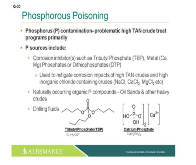
I am going to give a little background on phosphorous poisoning and then share one specific example we have seen in one of our refinery units. First of all, phosphorus is a strong catalyst poison. In our course materials, we say that 1% phosphorous on catalyst will reduce the activity by 50%. So, it is a significant poison. There have been examples of up to 3% phosphorous completely destroying the exotherm from a bed going down to almost nil. The deactivation mechanism is pore mouth plugging through surface deposition similar to nickel or vanadium. The common sources are crudes, drilling fluids, phosphorous-based corrosion inhibitors, and flow improvers. In particular, we have had more and more experience with phosphorous-based corrosion inhibitors, and the example I am going to discuss deals with that.
We have seen, in this example, the spent catalyst from the skim indicated up to 20% phosphorous on top-bed grading; so, significant amounts of phosphorous. And in this cycle, after seeing the exotherm decline, when we reloaded, we switched from the phosphorous-based naphthenic acid corrosion inhibitor to a sulfur-based inhibitor and saw the DT (differential temperature) decline halt or be held.
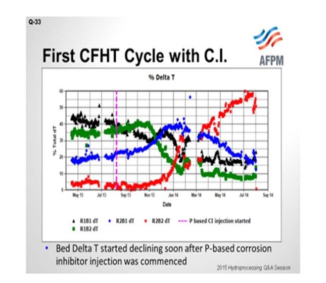
On the next slide is an example of the first cycle. The unit in question contains two reactors in series with two beds each; so the beds are delineated as Bed 1, Bed 2, Bed 3, and Bed 4. You can see that through the beginning of the 2013 cycle, the ΔTs (delta Ts; DTs; temperature differentials) were stable. The y-axis shows how the total temperature rise is distributed amongst the four beds. The vertical pink line marks the time when the phosphorous-based corrosion inhibitor was started. You can see that Bed 1’s temperature rise starts to decline. We actually tried to increase inlet temperatures to recover the ΔT, but it was not successful; the ΔT continued to decline. And as you would expect from plug flow and metals deposition, Bed 1 declines and Bed 2, which is the blue line, picks up the ΔT as it begins to decline. Bed 2 is the green. Bed 3 picks it up in the blue. And finally, when Bed 3 starts to decline, Bed 4 picks it up. We ended up changing the catalyst out in the cycle ahead of schedule.
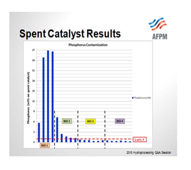
So when the catalyst samples were pulled out from the spent catalyst load, you can see that the Bed 1 samples were exceeding 20% phosphorous. If our threshold is 1% phosphorous or a 50% activity decline, even Bed 2 was above that and showed significant activity decline. We did have lower levels of phosphorous in Beds 3 and 4, and that is where the bulk of the HDS catalyst was located.
For the next cycle that started up after this, you can see the temperature rise response in the four beds, Bed 1, Bed 2, Bed 3, and Bed 4. The ΔT decline continued. You may ask, “Oh, did you guys at Valero not learn anything?” This delay at the start of cycle is the time it took us to get the spent catalyst sample results. When we unload the catalyst and send it to our supplier, we do not get those results back for several months. So it reinforces that having good technical service and timely return of spent catalyst samples can really help us make a change. As soon as we saw the high levels of phosphorous, we had a discussion and the refinery switched to a sulfur-based corrosion inhibitor. We worked with our chemical supplier. You can see that when we switched to that sulfur-based corrosion inhibitor, the ΔT stabilized. There was still some decline, as you would expect from metals poisoning throughout. However, the rapid decline that we observed in the previous cycle was not repeated.

So in summary, our Best Practice for phosphorous poisoning is to minimize the source of phosphorous poisoning. We do still use phosphorous-based corrosion inhibitors. They are very effective for naphthenic acid corrosion inhibition. However, it has to be an economic justification between the use for protecting the VGO (vacuum gas oil) circuits and any deactivation that may occur in a VGO hydroprocessing unit. There are demetallization catalysts that would be used for nickel and vanadium; they are also effective for trapping phosphorous. But still, a small amount of phosphorus goes a long way in terms of catalyst deactivation.
TEMME (Albemarle Corporation)
I agree with what Andy said. That is a really powerful example. Phosphorous is definitely becoming more problematic, especially with high TAN (total acid number) crude treatment programs. Andy has already mentioned the sources.
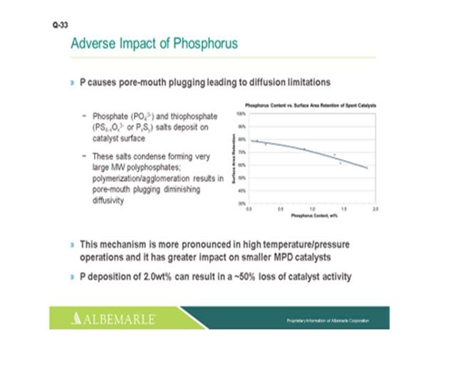
Phosphorous will cause pore mouth plugging leading to diffusion limitations. The mechanism is more pronounced with high temperature/high-pressure operations. And with that, the pore mouth plugging will have a greater impact on small pore size, smaller median pore distribution-sized catalysts. We have seen that phosphorous deposition of 2 wt% can result in a 50% loss of catalyst activity.
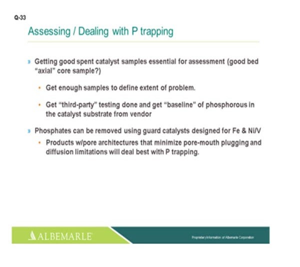
In terms of assessing and dealing with phosphorous trapping, as Andy indicated, getting good spent catalyst samples are essential for assessment. There are catalyst-handling companies that have core sample machines which work very well for getting a good axial core bed sample. Instead of having to try and vacuum off or pick samples out of flow bins, we want to make sure to get enough samples to define the extent of the problem. It does not hurt to get some third-party testing done, especially if they can do it in a quicker turnaround and get a baseline of the phosphorous and the catalyst substrate from the vendor to ensure that you have good accounting. And yes, phosphates can be removed using guard catalysts. They are designed for iron, nickel, and vanadium pickup, especially catalysts with the pore architecture that will minimize pore mouth plugging. We feel that catalysts with minimal diffusion limitations will deal best with phosphorous trapping.
PEDERSEN (UOP LLC, A Honeywell Company)
I will add that it is important not only to identify the concentration of phosphorus contaminant, but also the type of material with which this phosphorus is associated. Basically, the more acidic the phosphorus compound, the more lethal it is to your catalyst.
JEFF JOHNS (Chevron USA, Inc.)
I am curious about comments from the panel about protection from phosphorus in crude. Is there is any monitoring program or other procedures you have instituted to be able to prevent that poisoning? As an example, just so people are aware that that is a real problem, we had a diesel hydrotreater that completely went through a cycle in about six weeks due to phosphorus from crude poisoning. So, what have you done?
McARTHUR (Phillips 66)
I will say that we do not have a unit that has really had a significant phosphorus poisoning problem yet. So I do not think we have installed what I would call a top-of-the-line phosphorus monitoring program.
MORELAND (Valero Energy Corporation) All I want to say, Jeff, is that we would have been caught by something like that, too. We do not typically monitor for phosphorus in diesel streams. We have seen some phosphorus in some kerosene (kero) streams at one of our plants and some phosphorus-based fouling in the crude tower in the kero circuit. So maybe it is a similar case, but it did not seem to affect operations. In that refinery, the jet is not hydrotreated; so we would not have seen it in the hydrotreater. We have monitored it in VGO; but in diesel, we do not look for phosphorus very often.
NAGASHYAM APPALLA (Reliance Industries Limited) I have two specific questions. First, is there any industry-wide accepted limit of phosphorus in the gas oil stream going to the hydrotreater? Does anyone monitor this, and is there any permissible limit for the phosphorus levels? Secondly, in the presentation, it was mentioned that the customer switched from phosphorus-based chemistry to sulfur-based chemistry. Phosphorus-based chemistry is known to provide a better protection against the attack of naphthenic acid attack by forming a more stable Fe-S-P scale. Only sulfur-based inhibitors are not found to provide that level of protection. Also, as per experimental studies, the sulfur-based inhibitors need to be dosed in a higher proportion than the phosphorus-based to get the same level of protection. So, my question is: How did the customer ensure the same level of protection against corrosion from the naphthenic acid by switching to sulfur-based chemistry?
MORELAND (Valero Energy Corporation) I can answer the second question; I do not know about the first one. So in answer to the second part, we understood that switching to the sulfur-based inhibitor would be less effective for protecting against naphthenic acid corrosion. So the higher dosing went into the economic equation of how much high TAN crude we process at this particular facility. We have two different plants at which we are using the phosphorus-based corrosion inhibitor. One stayed with it and even dealt with the penalty on the hydrotreater downstream. The other, the example I showed, switched away from the phosphorus-based to the sulfur-based and then reduced the runs of high TAN crudes. As far as acceptable levels, I do not really have a number.
McARTHUR (Phillips 66)
The only time we review feedstock for phosphorus is if we have an opportunity feedstock come in, and then we would be looking for elevated phosphorus levels. We would steer away from something that had any appreciable amount of phosphorus, but I do not the number off the top of my head.
JAMES PROROK (Husky Energy Inc.)
About fouling in the crude tower, at the Lima Refinery, we experienced that phosphorus fouling there in a light gas oil cooler. We also experienced it then in the “water white” kerosene cooler – another air cooler – that basically plugged up with the same material, which shortened the life of the diesel hydrotreater catalyst.
MORELAND (Valero Energy Corporation)
We saw it in deposits in the crude tower. I do not know if we knew it ahead of time; because when we analyzed those deposits, that is when we saw phosphorus in those deposits. Is that a similar experience?
JAMES PROROK (Husky Energy Inc.)
After the pressure dropped in the kerosene section of the crude tower, we then got a sample where we could. We got a sample of the solids that were caught in a strainer on a pump, had them analyzed, and found out that there was phosphorus in that circuit. Then, we saw phosphorus in the heat exchangers downstream of that, on the way to the DHT (distillate hydrotreater).
MAUREEN PRICE (Fluor Corporation)
There is a question on this in the Crude Q&A tomorrow morning that covers phosphorous deposits in the crude unit equipment that may provide additional insight.
SALVATORE TORRISI, JR. (Criterion Catalysts & Technologies)
The panel talked about solids in the crude tower, and the focus of the question was activity on the catalyst. Can anyone on the panel comment about any impacts on pressure drop related to phosphorus?
McARTHUR (Phillips 66)
I do not have any experience with it, but my understanding is that there will be a pressure drop problem with phosphorus fouling on a catalyst, especially if you have a very low void space area where it is collecting. But again, we have not had that problem yet.
SALVATORE TORRISI, JR. (Criterion Catalysts & Technologies)
The experience I have seen has been more with regard to accelerated fouling in the feed preheat exchangers rather than in the catalyst bed itself.
MORELAND (Valero Energy Corporation)
Sal, you are probably as familiar with the unit as I am, so all I will add is that when you lose the activity this fast from phosphorus, the time onstream is not sufficient for development of a significant pressure drop issue. However, we have seen pressure drop start to increase. We ended up doing reactor skims before it really became a run limiter.
SALVATORE TORRISI, JR. (Criterion Catalysts & Technologies)
Okay, thanks. I was wondering about that because what happens is you use a corrosion inhibitor to neutralize the acids; and if you are not consistently neutralizing, organic iron can form as a result of the reaction of the acids with the equipment. We have observed some organic iron being converted back to solid iron sulfide by reaction with H2S in the reactor at the same time we observed the phosphorus being deposited in the catalyst bed. That is a secondary indicator that you may have a phosphorus issue because you are just starting to see some iron sulfide formation due to conversion of iron naphthenates. They can go hand-to-hand with phosphorus.
MICHAEL SCHMIDT (Haldor Topsoe, Inc.)
Phosphorus species are rarely found in typical crudes; however, some opportunity crudes – and in particular, renewable feeds – may contain significant amounts of phosphorus. Furthermore, phosphorus containing anticorrosion additives can be found in the diesel and VGO fractions. The phosphorus compounds are decomposed in the hydrotreater, and the phosphates react with the alumina support, forming very stable alumina phosphates. Accumulated amounts of phosphates will reduce the accessibility to the active sites of hydrotreating catalysts and lower the activity accordingly. Handling of organic phosphorus compounds in the VGO feed to FCC pretreaters or hydrocracker pretreaters is a major challenge in some refineries. The phosphorus deactivates the conventional catalyst fast and reduces cycle length dramatically. Often the phosphorus is co-present with silicon and calcium in the feed, and this combination makes the impact worse. The strategy for handling phosphorus is to capture it upstream the main high-active HDS catalyst. This is achieved by installing guard catalysts with improved porosity which allow the phosphorus to deposit in high amounts, thus protecting the main catalyst to a much higher degree. These guard catalysts, with proprietary properties and composition, will be able to prolong the cycle length of the unit.
Topsoe has a specialty product, TK-31, with a very high capacity for phosphorus (P). We recommend installing this phosphorus trap if the feed level is higher than 2 ppm P for protecting the downstream bulk catalyst from contamination and subsequent increased deactivation.
RALPH WAGNER (Dorf Ketal)
High temperature corrosion inhibitors used to control naphthenic acid corrosion are another source of phosphorus to be considered. A Best Practice is to use an inhibitor that is thermally stable and oil-soluble to control corrosion at the lowest possible phosphorus level. Many phosphate esters used for this purpose are vulnerable to thermal degradation. A thermally stable phosphate ester can reduce the level of phosphorus required to control corrosion by up to 80%, reducing exposure to the hydrotreater catalyst.
DORIAN RAUSCHNING (Criterion Catalysts & Technologies)
Phosphorus is increasingly being reported in a wide range of feedstocks including shale tight oils and recycle oils. The phosphorus is, in part, a result of different chemical additives. It may also be indigenous to some crude oils. Regardless of its source, phosphorous contributes to catalyst deactivation by depositing on the exterior surface area of a catalyst pellet and restricting hydrocarbon access to the catalyst pellet’s interior active metal sites. It has been detected on conventional hydrotreating catalysts with concentrations of 2 to 3 wt% and exhibits significant loss of activity. While narrower pore catalysts have limited phosphorous tolerance and deactivate quickly, wider pore demet catalysts can be effective in absorbing feed phosphorus and protect the lower bed primary conversion catalysts from phosphorous poisoning. Criterion offers a range of wider pore demet catalysts that facilitate greater interior pellet pore utilization for phosphorus deposition. These demet catalysts also provide some moderate hydrodesulfurization/hydrodenitrification (HDS/HDN) conversion activity while simultaneously trapping other feed contaminants such as Ni, V, Si, and As. One version of our MaxTrap demet catalyst demonstrated 10 wt% phosphorus pickup.

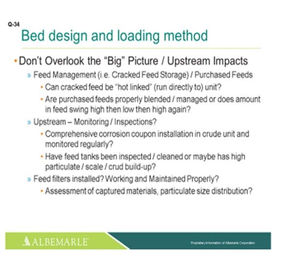
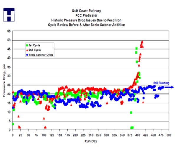
Question 34: Hydroprocessing reactor pressure drop can increase due to feed particulates, corrosion by-products and polymerization reactions. How can bed design and loading method be optimized to avoid pressure drop limiting the cycle length or throughput?
McARTHUR (Phillips 66)
There are a lot of approaches to helping out with pressure drop problems in a reactor, and I will go through them. We use all of these at Phillips 66. I will start at the top. There are particulate catching trays. These are relatively new. We have had limited use with these, although we think they have been fairly successful. We are reviewing potential applications at some of our other units that have some historical issues.
Many of our units have had, and some still do, trash baskets or scale-catching baskets. But in general, we are removing them because they are difficult to load around. Removing them tends to add a lot of time at turnarounds, and they can actually create some maldistribution issues at the top of the bed. That is not always the case. There are some cases where we choose to keep them in the reactor. It is a site-by-site decision.
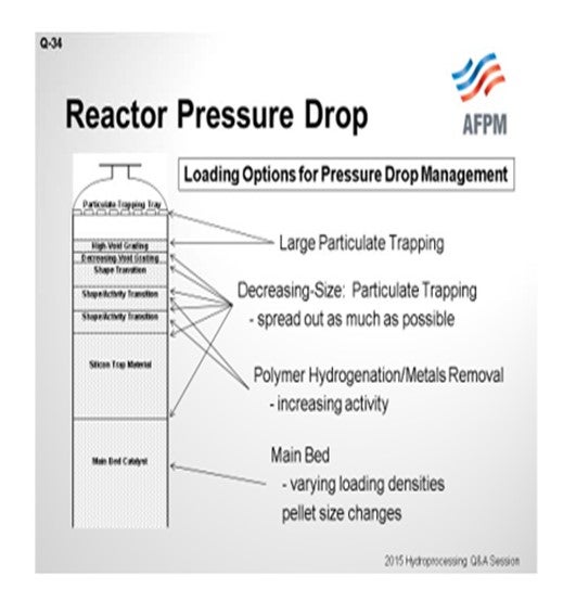
We think the primary workhorse is with the graded bed at the top of the reactor for two purposes. One is for particulate removal. There are many different kinds of particulates. They can come in with the feed and have several layers of size change. Shape change will spread this catch of particulates out across a large volume of material with a lot of void space and leave a lot of room for the oil to keep going through for longer and longer periods through the cycle.
Likewise, these graded beds can have some amounts of increasing activity built into them. We start with very low activity material to initiate some of those reactions, which helps avoid polymerizing compounds onto the main catalyst bed. The primary reaction here is saturation of the diolefin bonds that would otherwise, when hitting the primary high activity catalyst, polymerize right out. Also, if these polymers are going to foul out, I would rather they foul out in the high void space up in the graded bed rather than in the main bed.
Moving down to the loading method for the main catalyst bed, if there are typically DP (differential pressure) limitations associated with the main bed, then decreasing amounts of dense loading or eliminating dense loading can leave a little room for improvement in pressure drop across the reactor. This generally is not too significant, but it can help. And then actually, the choice of catalyst pellet size can be a factor as well. Smaller catalyst pellets tend to have a little higher pressure drop, so choosing a little larger pellet can have a small impact on DP across the main catalyst bed.
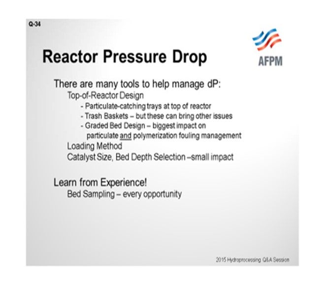
The diagram is what I have walked through. The main takeaway we would like to tell our engineers is that it is very site-specific; and really, the best way to learn the location of your issue is to do sampling at the end of the run, not just dump the catalyst and plan to load it like you loaded it last time because you got a “pretty good” run last time. It is really through sampling that you learn where the problem is in the reactor, what you are catching, and the cause of the problem. And then, you can optimize the bed for future runs after that.
WRIGHT (Hunt Refining Company)
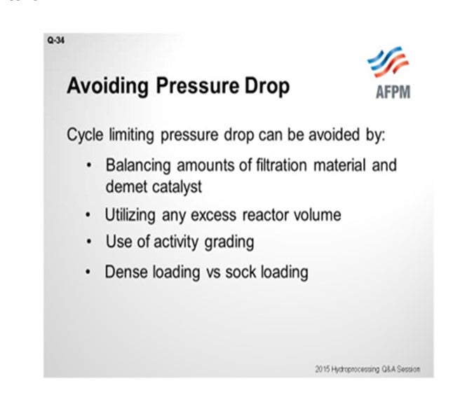
One method we have used to avoid pressure drop is, as Scott mentioned, balancing the amount of filtration material with the demet or graded bed. For example, our diesel hydrotreater was running into a particulate problem that resulted in high ∆P (delta P, pressure differential) on R1 (Reactor 1). So we stole some active catalyst volume and replaced it with filtration material to help us get the second half of the run finished. For our hydrocracker, we had the unusual experience of buying larger than required reactors relative to the design feed. [Laughter] We are on Cycle 2 now. In Cycle 1, we did not use up all of the space. We had some adventures in our feed resulting in some ∆Ps on R1, Bed 1. So during the skim, we filled up the volume that was there with the filtration material, again, to help us make the second half of the cycle. And as Scott mentioned, you can use the activity grading to help you balance pressure drop with activity, as well as employing dense versus sock loading at the appropriate times.
TEMME (Albemarle Corporation)
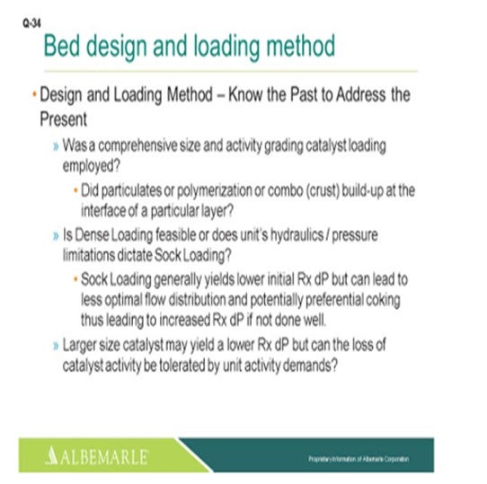
I agree with what Scott and Samuel just went over. Definitely, it is good to know the past to address the present. If you have something occur on the current cycle, it is hard to address quickly; but hopefully, you have had some past history to give you potential ideas for a path forward. You definitely want to make sure that a comprehensive size- and activity-grading catalyst loading is employed, looking particularly to see whether or not it is a particulates problem, a polymerization problem, or maybe a combination of the two and also whether or not that occurs at the interface of any one particular layer.
You have to check to see if dense loading is feasible. If not, do the unit hydraulics cause pressure drop limitations? In that case, sock loading has to be used. Yes, sock loading does give a lower initial reactor DP, but it can lead to less optimal flow distribution and potentially preferential coking, which then can lead to increased reactor DP if the sock loading is not done well. Another consideration is whether a larger sized catalyst may yield a lower reactor DP, but you must be certain that the loss of catalyst activity can be tolerated by the unit activity demands.
Really, you have to take a look at – I think in terms of a holistic way – the big picture and whether the upstream impacts are significant contributors. What is going on with the feed management? Is cracked feed storage problematic, in terms of nitrogen blanketing? Purchased feeds: Do they seem like a bad actor? Can the cracked feeds be hot-linked to run directly to the unit instead of going out to the storage? Are the purchased feeds properly blended and managed where you will not have purchased feed volume swings from high to low and back to high again, which can cause some issues, in terms of hydrogen consumption variability and potentially DP type of problems?
Upstream, especially at the crude unit: Are there good monitoring and inspection programs? Is there a comprehensive corrosion coupon installation in the crude unit that is monitored regularly? Have feed tanks been running for 10 years? Maybe they have not been inspected or cleaned, and you just have a high level of particulates, iron sulfide, or other solids buildup in the tank that is now working its way over into the unit. Now a lot of people have feed filters, but are they being worked on and maintained properly? And then there is their assessment of the captured materials. Have a particle-size distribution assessment been done to help give you an idea of how you might put your grading system together? So, we feel that all of this can be very helpful in avoiding pressure drop problems.
JAMES (TIM) CAMPBELL (Eurecat U.S. Incorporated)
I want to add a comment for those folks who use regenerated catalysts; because many times, there is a concern about pressure drop with regenerated. At Eurecat, we address that. We can test for relative pressure drop of the regenerated catalyst versus its fresh version and give you a factor that you could use in your evaluation.
SHRIKANT MADHAV VAIDYA (Indian Oil Corporation Limited)
I have one observation. The minute we have a recycle gas flow failure, after which the plant gets restarted, we have a step change in the R1, Bed 1∆P. So, could there be any reason for that?
McARTHUR (Phillips 66)
I guess there could be several reasons. If it typically trips your heater when you lose your compressor, the rapid cooling of the tube will sometimes cause coke material to slough off the tubes. And then when you start back up, you will carry that back onto the reactor bed. We have had that problem a few times. Also, any significant period of time where the oil on catalyst is a hot temperature with no hydrogen there, you are going to have some coking issues and fouling with that, too.
WRIGHT (Hunt Refining Company)
We were having recycle gas compressor issues in Cycle 1, so we were getting these nuisance trips. We saw that the fouling material in the CFEs (combined feed exchangers) would then flow to R1, Bed 1. And later on in the cycle, we were having charge heater limitation; so we intentionally pulled out the feed in order to slough the foul end off of the CFEs and onto the filtration material of R1, Bed 1. So we serendipitously observed that phenomenon and used it to our benefit later on.
PANKAJ DESAI [Shell Global Solutions (US) Inc.]
I agree with what the panel has said that having a well-designed graded bed is necessary to mitigate pressure drop issues. However in spite of that, upsets can occur. If you need extra insurance or protection against pressure drop, we offer a couple of devices in our reactor internals portfolio. If it is simply a case of inorganic iron or scale deposits, then we offer a simple scale-catching tray that helps to minimize pressure drop. For more complex feedstock issues with gum precursors or treating cracked feedstocks, we offer a more sophisticated device called a filter tray that helps to minimize pressure drop. Both of these devices sit in the dome of the reactor and do not take away any active space in the reactor from loading active catalyst.
JEFF JOHNS (Chevron USA, Inc.)
We have already invited you to come to the Principles & Practices session tomorrow morning. We have an hour set aside to continue the discussion. I appreciate the good responses from the panel. We hope to continue with more discussion and less advertisements.
SERGIO ROBLEDO (Haldor Topsoe, Inc.)
A properly designed catalyst system can go a long way in mitigating pressure drop issues. A key factor for designing a catalyst load is a properly designed graded bed. A fixed bed catalytic reactor can be graded in a number of ways, depending on the nature of the feedstock. We must differentiate between contaminants entrained in the feed as opposed to compounds, such as diolefins or metals-containing molecules in the feed that react upon entering the reactor environment and have the tendency to produce byproducts [polymer, Fe (iron), Ni (nickel), and V (vanadium) deposits]. In extreme cases, polymerization can manifest itself as a very hard crust which, in some cases, has to be jack-hammered out of the unit. Such agglomeration causes bypassing of catalyst and maldistribution in the catalyst bed.
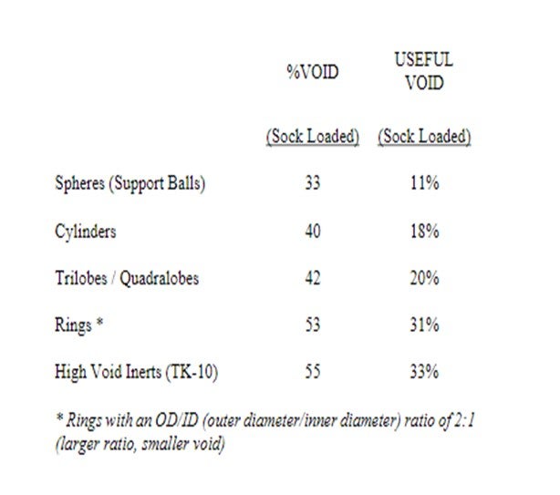
In other cases, the material is very fine, in terms of particle size (5 to 10 microns); and although not forming a crust, it will also deposit in a small area, resulting in a reduced void fraction which causes the pressure drop across the catalyst bed to increase exponentially. Our experience, since Haldor Topsoe, Inc. invented grading in 1979, shows that the critical point is reached when the available bed void is reduced to approximately 20 to 25%. We therefore prefer to use what we term “useful bed void”. This means the fraction of the reactor void which is available for deposition or storage of contaminants before the critical limit where the pressure drop increases. Please refer to the following table:
Inorganic material such as iron or polymers can quickly fill up the spaces between particles of a main bed catalyst effectively cementing them together, causing maldistribution and eventually crust formation with a resulting increase in pressure drop. The properly designed graded bed system can extend the cycle length of a main bed before pressure drop becomes an issue.
Fouling of a catalyst bed can be caused by a number of different factors or sequence of events in the refinery; however, in most cases, one of the most commonly encountered contaminants is iron. Organic iron can be present in refinery feedstocks; but more often than not, the iron originates from corrosion within the refinery itself. This is especially true for refineries using naphthenic-type crude. Processing these high TAN crude types accelerates corrosion in plant piping, tankage, etc., due to the presence of naphthenic acids. This iron can have a wide range of particle size distribution ranging from submicron up to large flakes.
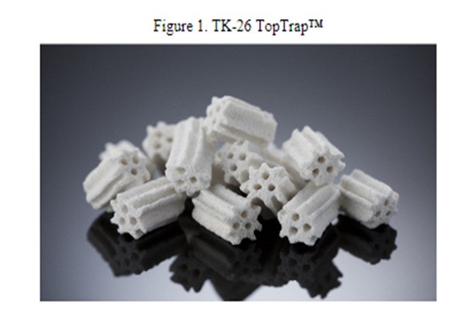
When grading for iron, the graded bed system must be able to handle the iron in all its sizes Haldor Topsoe, Inc.’s shape-optimized TK-26 TopTrap™ is the successor of our very successful TK-25 TopTrap™. The optimized shape of TK-26 TopTrap™ provides an improvement in pickup capacity of 21%. TK-26 TopTrap™ is designed to load with an interstitial void of 61% and an additional 25% void in the pore system, for a total void volume greater than 85%. This gives TK-26 TopTrap™ the ability to trap not only larger quantities of deposits but also the ability to trap the smaller sized particulates. Larger-sized material deposits in the interstices between the individual particles. Fines or smaller-sized materials enter the TK-26 TopTrap™ pore system and are trapped within the structure of the particle itself. Not all grading is created equal, and it is not just a question of creating a high interstitial void fraction. Porosity and surface area are also important functionalities for graded bed material designed to trap particulate matter. Please note that the material trapped in the pore system of TK-26 TopTrap™ will not add to the pressure drop. This is the reason why TK-26 TopTrap™ is more effective in mitigating pressure drop issues than other ceramic trap materials in the marketplace.
This specialty trap would be loaded right under the high-void, high-density topping layer, such as TK-10 or TK-15. TK-10 or TK-15 act as a hold-down, as well as storage space, for larger size inorganic material.
For units processing a high number of cracked stocks, a high quantity of olefins – which can cause large temperature rises in the reactor – need to be considered when designing a graded bed. In the presence of small amounts of oxygen, or at elevated temperatures above 450°F, these molecules will radically polymerize to form gum that can foul exchangers or reactors causing poor heat transfer, as well as high reactor pressure drop. If the feed blend contains coker naphtha, then we also need to consider the highly reactive diolefins compounds, which are severe coke precursors.
Cracked stocks should preferentially be sent directly from the upstream unit to the hydrotreater to prevent contamination with oxygen. Even straight-run stock that may be part of the feed component must be prevented from being contacted by oxygen by using nitrogen-blanketed storage tanks.
Even without oxygen ingress, the diolefins in the coker naphtha can polymerize at elevated temperatures. With high olefinic and/or cracked stocks, saturation will occur regardless of catalyst activity. However, an option does exist whereby the reaction front is spread out over a large volume, rather than at the top of the bed, or at the reactive interface between the inert topping and active catalyst.
This option is referred to as an “activity gradient”. We use a number of low- to medium-activity Raschig ring-shaped catalysts in 1/8” and 3/16” sizes on top of the main bed catalyst. Furthermore, high void inerts and rings have the advantage of improving the radial distribution and are also recommended to enhance distribution.
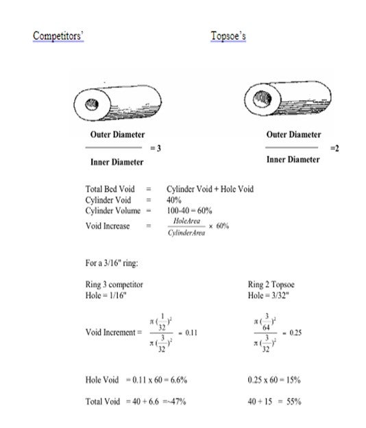
Haldor Topsoe, Inc. produces our 1/8” ring catalysts with a very large ID of the hole to allow for maximum feed contaminant capacity without sacrificing the crush strength. The ratio of the OD/ID for our 1/8” rings is 2:1. Furthermore, we manufacture all of our grading material to strict ISO (International Organization for Standardization) specifications from fresh raw material and not from scrap catalyst or regenerated catalyst, which may contain impurities from its prior use.
The particle size will definitely impact the SOR (start-of-run) pressure drop of the catalyst bed because each particle has an inherent interstitial void. For comparison, a 1/16” TL (trilobe) will have, on average, about an 80% lower SOR pressure drop than a 1/20” TL. This will have minimal to no impact on the SOR activity of the load but will allow for a larger window between SOR and EOR (end-of-run) pressure drop. This strategy can be further refined in reactors with multiple beds where a larger sized catalyst can be installed in the top bed where pressure drop is a concern, and a smaller sized (i.e., 1/20”) catalyst installed in the lower beds where pressure drop is less of an issue.
The same strategy is also true for loading method. On average, the SOR pressure drop of a dense loaded bed will be twice that of the same bed sock loaded. Therefore, sock loading can be considered when pressure drop is severely limiting cycle length and not activity. However, sock loading will mean that the activity will be about 15% lower than for a dense loaded bed. Again, the same method of titration can be employed in sock versus dense loaded portions of the catalyst bed. In multiple bed reactors, it is sometimes advisable to sock load the top bed and continue dense loading the lower beds. This will minimize the impact on the overall activity of the system but will improve the window for pressure drop build on the top bed where pressure drop is typically an issue. One point to keep in mind is that radial flow profiles in a bed may be impacted when changing to sock loading which could limit the cycle length due to peak operating temperature.
In units with severe pressure drop issues and where activity is not an issue, both a size change and loading method may be a viable solution. These two approaches – size and/or loading method – can also be employed in units with pressure drop issues in lower beds.
Scale Catchers
In addition to an effective graded-bed system, Haldor Topsoe, Inc. also recommends the use of our patented scale-catching trays, which are placed in the top of the reactor. The tray is installed above the tangent line to avoid reducing the catalyst volume. Haldor Topsoe, Inc. has designed scale-catching trays for both mixed-phase and 100% vapor-phase operation.
Clients have seen as much as a doubling of the cycle length after installing our scale catching trays, and we often find two to three inches of material deposited on the tray. This material would have fouled the catalyst bed without the presence of the scale catcher tray. This gas oil hydrotreating unit increased the cycle by 100% after installation of a Topsoe scale catcher.
CHRIS STEVES (Norton Engineering)
All catalyst vendors provide hydroprocessing reactor grading design that can help to manage pressure drop during the catalyst cycle in order to keep reactor throughput as desired. It is important to understand the historical sources of pressure drop in the unit, though, so that the proper grading system can be chosen: a system that is designed to handle particulate contaminants may not work as well in a situation where the pressure drop is due to polymerization reactions. Samples from the top of the bed after every run should be used to confirm sources of pressure drop and then taken into account when designing the grading system.
DORIAN RAUSCHNING (Criterion Catalysts & Technologies)
Catalyst bed pressure drop growth mitigation can be achieved by integrating the results of empirical bed unloading observations, spent catalyst fines analysis, and subsequent design of a deep bed filter. While a multi-cycle iterative approach using trial and error can often result in the final development of a deep bed filter system, a more rapid resolution can be obtained by taking the time to gradually remove (vacuum) the top bed catalyst, visually observe the location and quantity of dust/fines/crust and collect intermittent spent catalyst/crust/dust/fines samples for chemical and particle size distribution analysis.
Based on the combined observations and analytical results, a deep-bed filter can be developed which utilizes void fraction grading of specialized grading materials and catalysts that facilitate selective trapping of different sized feed particulates, gums, and/or soluble metal naphthenates. A large diameter and intersticial void catalyst layer is first used to remove large-sized feed particulates while simultaneously still providing sufficient void space to permit the medium/small-sized particulate to penetrate deeper into the reactor and not form a high-density crust. Subsequent ever-smaller diameter and intersticial void fraction grading or catalyst layers are then used to promote further selective feed particulate removal until the primary conversion catalyst is reached. These layers are all sock loaded. The net effect of such deep-bed filters is that the feed particulate is distributed over a greater depth of reactor volume and do not form immediate, high density, narrow layers that restrict feed or treat gas flows.
The deep bed filter should also provide an activity gradient to mitigate the formation of adhesive gums that can form from olefinic polymerization reactions. Feed unsaturates can react to combine longer chain polymers which can act as gums and form coke that bridges catalyst pellets. In addition, these gums interact with feed particulates causing rapid pressure drop growth. To mitigate these reactions, the deep bed filter should be graded for activity as well. The bed’s upper layers should have lower activity catalysts to slow down the rate of polymerization and promote hydrogenation. The deep bed filter’s subsequent catalyst layers’ activity begins to increase as the concentration of polymer-forming compounds decreases.
Criterion’s OptiTrap™ product line is designed to provide a wide range of top-bed grading catalyst products from which a deep-bed filter can be constructed. OptiTrap™ products offer selective particulate removal in combination with an activity gradient. In addition, Criterion has extensive troubleshooting experience in resolving reactor pressure drop growth issues in naphtha, distillate, FCC PT, and hydrocracking applications. Criterion also offers a full range of research and analytical support.
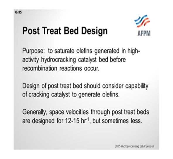
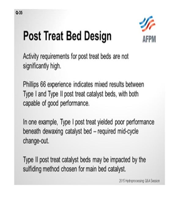
Question 35: What important parameters do you consider in designing a post-treat bed for a hydrocracker? What are the advantages and disadvantages between Type I and Type II catalyst when used as a post-treat bed in a hydrocracker?
McARTHUR (Phillips 66)
The post-treat bed is generally positioned at the bottom of the reactor in a hydrocracking reactor, and its main purpose is to remove sulfur compounds that have recombined with the organic compounds coming out of the reactor. Usually, it is a function of olefins that are generated in a hydrocracking catalyst. In our experience, designing the post-treat bed should be a little dependent on the type of cracking catalyst it supports. Now we have had some dewaxing catalyst post-treat beds that have performed poorly, and we think it was just because they were undersized. General space velocity recommendations, as we have heard, range from 12 to 15 hr1 (inverse hours). In our experience, I was just talking about how that was not enough and that we needed even a lower space velocity.
End-of-run post-treat bed temperature is also a consideration. The higher the temperature at the bottom of the bed, the more prone those recombination reactions are to occurring. But as far as Type I and Type II catalysts, olefin saturation and sulfur removal reactions are not especially difficult reactions. So, in theory, we do not really think there would be a need for a Type II catalyst in a post-treat bed. We do have some pretty good experience with both. I am going to put up a couple of slides and walk you through them.
This first example is on a hydrocracker in one of our refineries: two different cycles with very similar cycles, as far as feed and operating conditions. They may not be exactly apples to apples, but we think they are pretty close. One initial run had a Type II post-treat bed, as shown in blue. It had a pretty good performance throughout the cycle with mercaptan sulfur in the light hydrocracking stream. A subsequent cycle, as shown in red, had a significantly worse performance. This subsequent cycle was with the Type I post-treat catalyst.
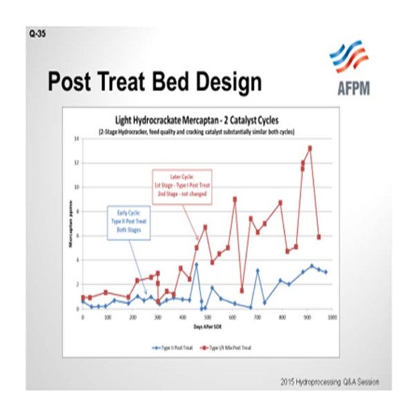
The second slide shows another unit at a different refinery. I actually have two cycles plus part of a third cycle. As you can see, Cycle A (in blue) was the Type I post-treat. It actually did pretty well through most of the cycle. The second cycle, in red, was a Type II post-treat bed, which had enough sulfur recombination in it that it was causing some blending issues by the end of the run. This third cycle, again, was a Type II post-treat. The sulfiding methods were different between the two Type II catalysts. The gas-phase sulfiding was not recommended by the catalyst providers, so we might have shot ourselves in the foot there.
If I have been coherent with my descriptions here, you will see that our data conflicts and that we do not really have a clear picture on which one is better: Type I or Type II. That is where we stand.
PEDERSEN (UOP LLC, A Honeywell Company)
The interest in post-treat catalyst, and the associated issue with mercaptans formation, primarily relates to the naphtha fractions. As shown in this example, higher sulfur and higher mercaptans content are typically found in the lighter fraction. In this chart, sulfur content is shown on the Y-axis and time onstream on the X-axis, where red symbols represent the light naphtha data and green shows the heavy naphtha measurements.
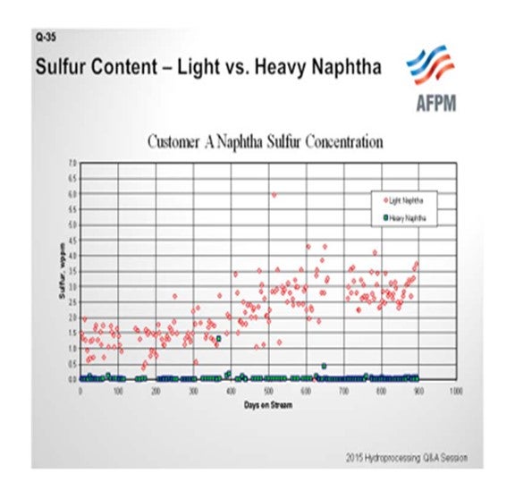
There are two factors that contribute to this type of result. First, the formation of light mercaptans is much more thermodynamically favored than the formation of heavy mercaptans. The second is, as we have all experienced, that the selectivity for heavy naphtha in a hydrocracking operation is much higher than for light naphtha; so we have a much bigger dilution effect in the heavy naphtha fraction.
As Scott already indicated, our purpose in looking at installing a post-treat catalyst is to saturate olefins, which are precursors to mercaptans formation downstream. Type I catalysts typically have more than adequate activity to accomplish the goal of saturating olefins. If this is the situation in which we find ourselves, Type II catalysts may actually be detrimental in that Type II catalysts are often formulated with a higher level of acid function. More acid function may result in slightly higher olefins content coming out of the reactor. If conversion of organic sulfur compounds is really the objective, then it can be important to use a higher activity catalyst like, perhaps, a Type II catalyst. And as Scott indicated, it may be necessary to drop the space velocity considerably in order to achieve this goal. Just one more comment: We very commonly install post-treat catalyst in hydrocracker operations. If sulfur in the naphtha fractions is not an issue, either due to blending specifications or the fact that the material will be treated again downstream, the space used for post-treat catalyst may be more optimally loaded with hydrocracking catalyst.
SUBHASIS BHATTACHARYA (Chevron Lummus Global LLC) I would like to add that the difference between Type I and Type II is mostly evident during the startup. Type II catalyst uses a particular reagent to get a better dispersion of the metals during startup. So as long as you are using a hydrotreating catalyst, whether it is Type I or Type II, if it does not have any acid/cracking function, it will not introduce more mercaptans. So if you have a Type II hydrotreating catalyst as your main hydrotreating bed, then you can continue with the same as your mercaptan control layer or the post-treat. As Scott showed with some of the results from his testing, it is very clear that Type II, with better metal dispersion, showed much better mercaptan control in those layers. So I would like to say that you do not have to go for Type II specifically for post-treat. You can continue with the same catalyst system you already have for your primary hydrotreating function.
DAVID VANNAUKER (Haldor Topsoe, Inc.)
The first question to answer is the purpose of the post-treat bed. Is it to handle mercaptans or to provide additional desulfurization of the partially cracked and easier to treat molecules? The traditional purpose is to saturate olefins to prevent mercaptan reversion that is most prevalent in the naphtha fractions. Other refineries require additional volumes of hydrotreating catalyst to provide additional desulfurization. Many units have been expanded and today are running with twice the original feed rate. In some of these units, the cracking catalyst volume is on the edge of the required amount, and the partial conversion of molecules occurs. In addition to mercaptans, thiophenes are sometimes found in the naphtha and diesel fractions. For these units, additional post-treat catalyst may be warranted and justified to improve the desulfurization. For naphtha streams, the costs of additional processing or sulfur traps can be avoided; and for diesel, the lower product sulfur can provide additional blending flexibility in the refinery.
The main advantage for Type II catalysts is the activity. Type II catalysts have higher activity. Therefore, a smaller volume of post-treat catalyst can be employed. However, Type I and Type II catalysts can both provide good performance. Startup procedures are another key consideration. Please check with your vendor to ensure that the startup procedures are compatible with the catalyst. Since Haldor Topsoe, Inc. Type II catalysts are manufactured to enable the standard startup, the traditional startup procedures can be employed.
JOE FLORES (Criterion Catalysts & Technologies / Zeolyst International)
Space velocity is an important factor to consider when designing the height of the post-treat layer, and the post-treat bed is typically designed with a LHSV in the 12 to 25 range. More severe operations tend to require more catalyst, and the amount of H2S in the recycle gas also has a bearing on amount of catalyst required. Prior experience in a typical service is helpful. Since post-treat beds are only needed for easy-to-treat sulfur species formed by recombination (i.e., mercaptans), Type II catalysts are typically not needed as their higher activity is not utilized. Since the post-treat catalysts tend to operate at high temperature at the bottom of the cracking catalyst bed, catalyst robustness is also a key consideration. Type I catalysts are usually all that are required.
Question 36: What has been your experience regarding selectivity and activity when using regenerated hydrocracking catalysts versus fresh catalysts? How do results vary with catalyst type, unit objectives, and conversion targets?
PEDERSEN (UOP LLC, A Honeywell Company)
There are well-established track records for regeneration and the reuse of spent hydrocracking catalysts, depending on service history, catalyst type, and conditions in which the catalyst was recovered. These catalysts can be returned to fresh or near-fresh performance, in most cases, and often come back basically equivalent to fresh. However, to ensure successful hydrocracking catalyst reuse, it is important that the catalyst did not experience extreme temperatures during the operating cycle and that there was no significant amount of metals contamination on the catalyst during the prior cycle. It is also important that during the regeneration of the catalyst, the temperature is carefully controlled and the regeneration is conducted according to the recommended procedures in order to recover catalyst activity.
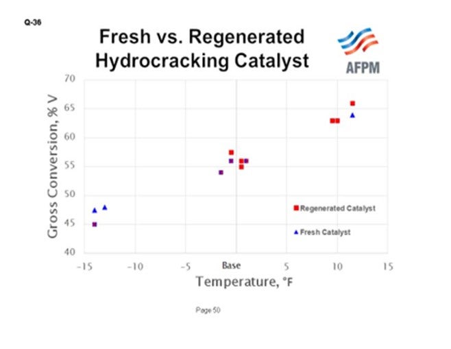
This chart shows results from a pilot plant comparison of commercially regenerated catalyst that was run through one cycle versus fresh catalyst which was a sample of the material that had been loaded for that cycle. The data show that at the same operating temperature, the same conversion was achieved, implying full recovery of activity. What is shown in this chart is gross conversion on the Y-axis and temperature on the X-axis. Blue represents the fresh catalyst data points; the red data points indicate the regenerated catalyst.
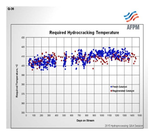
Similarly, in back-to-back commercial operation shown on this chart, we see required temperature for constant conversion versus time onstream. Blue, again, is fresh catalyst, and the data points in red indicate the performance of the regenerated catalyst. In this case, equivalent performance on cracking catalyst activity between the fresh and the regenerated catalyst is observed. The operating data also show very good catalyst stability throughout the cycle for the regenerated catalyst (red data points).
These are two examples of good outcomes. This is not a guarantee that regenerated catalyst performance is always good. I will remind you of my earlier point that it is important to pay attention to how the catalyst is handled in the prior process cycle, in order to ensure success on regeneration. Although regeneration of distillate selective catalyst is most common, catalysts across the activity spectrum have been successfully regenerated, in fact, multiple times in many cases. We tend to see a bigger shift in performance and properties with the max naphtha catalysts versus distillate catalysts, if there is a deviation from fresh catalyst performance. Typically, when we see good results like those indicated in the charts, we are talking about catalyst activity from the standpoint of the cracking function.
However, as we know, hydrocracking catalyst is bifunctional. Regeneration does not always produce equivalent recovery of the hydrogenation function. In those cases, the selectivity might suffer a little relative to the fresh catalyst; although in some cases, the selectivity comes out just as good as fresh.
Generally, if regenerated catalyst is used in low conversion operations, there is a lot less sensitivity to differences in performance. So, there is a lot more flexibility in those cases for selecting regenerated catalyst. In some instances, it may be necessary to install some fresh catalyst to make up for a potential loss of activity or shortage in quantity of the regenerated catalyst. Our recommendation is to load the fresh catalyst (the higher activity cracking catalyst) nearer the reactor inlet, primarily from a temperature control and safety standpoint.
McARTHUR (Phillips 66)
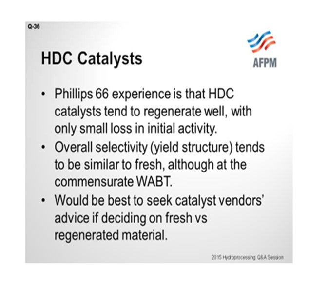
Phillips frequently makes some use of select regenerated cracking catalysts in our bed design. This is catalyst for which we know the operation history, so it is typically catalyst from our own units. Our experience is that a hydrocracking catalyst regenerates fairly well and with only a small loss of initial activity. The yield selectivity tends to be similar to fresh catalyst when run at similar operating temperatures. The yield decline over the run is similar to, or maybe even a little better than, that of fresh catalyst. But in our experience, it is best to bring in the catalyst vendor. It will be worth your decision when you are deciding whether or not or how much of it to load.
WRIGHT (Hunt Refining Company)
We are on Cycle 2 of our hydrocracker. We have not used regenerated catalyst yet. We plan to use it in Cycle 3 relative to the fresh catalyst though. The pilot plant data shows that the selectivity is higher, but the activity is slightly lower.
JAMES (TIM) CAMPBELL (Eurecat U.S. Incorporated)
Is there any difference in your comments for nickel tungsten versus nickel moly hydrocracking catalyst? Have you seen any difference of regen versus fresh?
McARTHUR (Phillips 66) I am going back in memory here, which is a little scary; [Laughter] but no, we do not see a lot of difference between the two.
SHRIKANT MADHAV VAIDYA (Indian Oil Corporation Limited)
On the presentation slide that Mr. Pedersen of UOP showed about the regenerated catalyst and fresh catalyst, there was a comparison between fresh and regenerated catalyst activity and selectivity, which showed the regenerated catalyst data for the fresh catalyst as being quite encouraging. But still, invariably the users always go for the new catalyst. That is the general feeling. So why is it not so popular to use the regenerated catalyst if the results are going to be so good? Why is there no confidence among the users? Why, therefore, are they not preferring the use of regenerated catalyst?
PEDERSEN (UOP LLC, A Honeywell Company) That is a good question. Why is there not more use of regenerated catalyst? I think that is somewhat of a company-specific and regional-specific question. Some refiners are a lot more risk-averse than others. As I indicated in my comments, you do, of course, have the potential to recover activity very well through regeneration, but it is not always guaranteed. The second factor is that in a fair number of cases, a refiner will contaminate his catalyst during the cycle, either through temperature excursions or through lack of adequate demetallization pretreat; and in that way, he will diminish the suitability for the catalyst to be regenerated. There are some lower activity amorphous catalyst systems where there is no pretreat, so the contamination with metals is a higher risk in those cases.
MORELAND (Valero Energy Corporation) In Valero, we have not used regenerated hydrocracking catalyst. And in our opinion, when we look at a catalyst selection for a hydrocracker, we are almost always trying to consider the latest, greatest generation just from the yield perspective. So even if there is no activity or selectivity difference between a regenerated catalyst and a fresh catalyst, there is potentially a new grade out from a catalyst supplier – like UOP, Criterion, or Chevron – that has higher yield and better activity than even the fresh catalyst from the previous generation.
PEDERSEN (UOP LLC, A Honeywell Company) There is one more factor that we probably should mention. With the use of regenerated catalyst, it is typically required to keep a spare batch of catalyst. The reason is that turnaround on catalyst regeneration, particularly for refiners who are in a more remote location, does not allow for dumping regeneration and reloading all in one turnaround.
TARIQ MALIK (CITGO Petroleum Corporation) As owner-operators, we are interested in the run-length. When you are primarily focused on run-length, including conversion and yields from your hydrocrackers, you are scared of regenerated catalyst. You do not know what you or the previous owner have done to that catalyst, so you always go for fresh catalyst.
MORELAND (Valero Energy Corporation) Well, I think what you are saying is that the risk is on me, or on us as the SMEs (subject matter experts) if we recommend a regenerated catalyst. It can only go poorly for us. [Laughter]
TARIQ MALIK (CITGO Petroleum Corporation) That could be a career-limiting move.
MORELAND (Valero Energy Corporation) That is correct. [Laughter]
DAVID VANNAUKER (Haldor Topsoe, Inc.)
The catalyst regeneration process exposes the catalyst to high temperatures and steam. The hydrocracking catalyst can lose metals functionality, zeolite functionality, or both. A loss in metals functionality leads to less aromatic saturation and more nonselective cracking. Light gas yields increase. A loss in zeolite functionality can lead to high temperatures for normal operations and an increased sensitivity to nitrogen slip and more difficult feeds. If the unit requires high conversion, the previous conversion level may not be able to be reached. The regeneration quality determines the results. Some units have been able to successfully use regenerated catalyst with minimal impact, while others have seen increases in light gas production and catalyst deactivation rates.
JOE FLORES (Criterion Catalysts & Technologies / Zeolyst International) Typically, regenerated hydrocracking catalysts exhibit reduced activity and selectivity when compared to fresh catalyst. The amount of reduction is usually dependent on the service the catalyst was in its previous life, i.e., how long it was in service, the final severity before the catalyst was taken offline, and whether it was subjected to any temperature excursions. Regenerated catalysts can have a place in a replacement catalyst load as a cost-effective alternative to fresh. Oftentimes, a higher activity catalyst that is regenerated can be used in place of lower activity fresh catalyst. Each individual situation is unique, and the unit objectives of cycle length, desired conversion, and yield selectivity need to be considered when employing regenerated catalyst. Regenerated catalyst can be evaluated in a pilot plant to baseline the remaining activity and yield selectivity before it is recommended in a replacement load.