New Orleans Tour
Split into smaller groups for concurrent tours of more restaurants or venues based on individual preference
Session Start End
-
TRAGESSER (KBR)
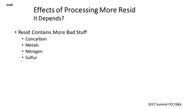
I will let my colleague Mike handle the catalyst side of this question. Like most things in FCC, the answer starts with, “It depends”, which really applies here as this is a very open-ended question. But in general, as resid processing is increased, more bad actors will be included in the feed, such as Concarbon, metals, and sulfur.
Higher Concarbon in the feed will increase the coke make, assuming operating conditions are not adjusted to offset it. Therefore, more air will be required for the higher coke make. If the air blower is at capacity, then oxygen enrichment is a possible option to deal with the higher coke make. However, if the air rate is expanded, it will be important to review the regenerator cyclones to ensure they can handle the higher air rate.
Regenerator bed temperature could also be an issue with higher Concarbon. This can potentially be addressed by modifying operating conditions, such as lowering the feed preheat. If enough resid is being processed, it may be necessary to add a catalyst cooler to maintain the bed temperature.
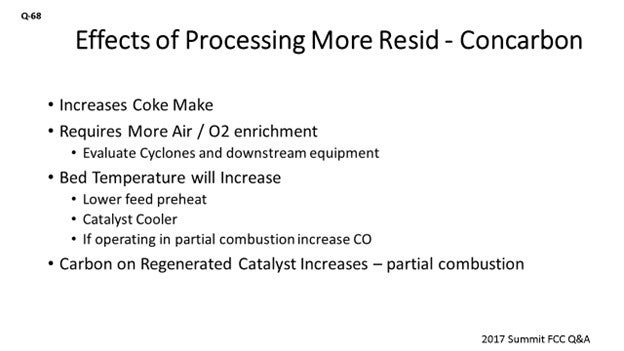
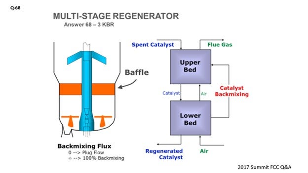
If your unit is operating in partial combustion and has a higher-than-desired carbon on regenerated catalyst, KBR offers a technology called RegenMax™, as I mentioned earlier, which essentially creates a two-staged regeneration effect in a single vessel. This modification is accomplished within the regenerator by installing a baffled packing section, which will significantly minimize vertical mixing of the catalyst such that the upper section operates in partial combustion and the lower section operates in complete combustion burning the catalyst clean.
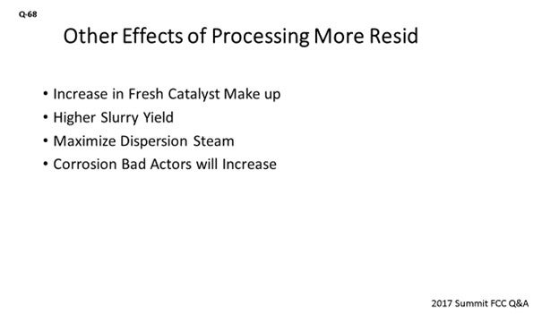
It would also be a good idea to maximize the dispersion steam to your feed nozzles, or even consider replacing them with a design that allows the use of more dispersion steam.
A properly performing stripper is even more important when processing resid to minimize hydrocarbon undercarry, so you may want to look at that as an option.
Processing more resid will also increase slurry make, so it would be a good idea to make sure the slurry circuit can handle the extra material.
FEDERSPIEL (W.R. Grace & Co.)
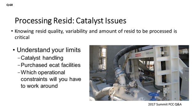
What we consider to be critical in this assessment of processing resid – at least catalytically – is to really understand the quality, variability, and amount of resid to be processed; because depending on the answers to those questions, there will be two different pathways available. If you are pursuing a short-term opportunity, then changing over to a new catalyst will effectively not be an option for you. You will need to examine different potential solutions. So, in the shorter term, one option that might be available could be the use of purchased e-cat as a flushing agent; again, to handle the increased metals, you will be moving more catalyst around.
Knowing your limits of catalyst handling will be critical, as will making sure you have facilities to handle that purchased e-cat. Understanding which operational constraints, you might have to work around and what you expect to run into when you process the resid will play a part.
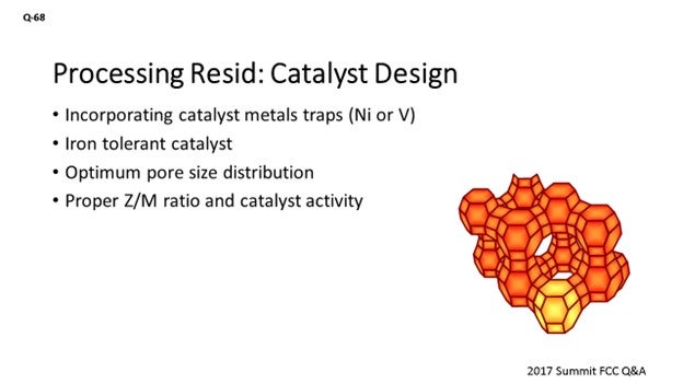
Assuming this will be a longer run and you will be able to change over your catalyst, then we can start playing around with the design of the catalyst and get one that is proper for handling resid in there. We can incorporate metal straps for the nickel and vanadium we would expect to see. There is an iron-tolerant catalyst that can be used. It is also important to ensure that the pore size distribution is optimized so we do not end up in diffusion limitations, which could result in an unnecessarily high slurry yield. We also need to be critical about optimizing the Z/M (zeolite/matrix) ratio and the overall catalyst activity to address the higher amount of coke that processing resid brings to the table.
BHARGAVA (KBC Advanced Technologies, Inc.)
I want to add that KBC recently evaluated resid processing in one of our client sites by taking the resid from their crude unit and trying to put it into the existing FCC that was designed for gasoil operation. Just as a word of caution: Most crudes result in a heavy load of metals, Conradson carbon, and asphaltenes on the FCC. Very few crudes are suitable for any even 10 or 20% resid processing. So, if you are going to process resid, you might have to reevaluate your crude composition and look at more paraffinic crudes that have low metals and asphaltenes to make sure your regen temperature and catalyst loadings allow you to process that resid.
Resid processing will again increase fouling coking in the main fraction of the bottom section. In the previous question, we talked about having additional exchangers, using antifoulants, and injecting LCO to help with the fouling on the exchangers. For refineries that do not have a post-gasoline hydrotreater on the FCC gasoline, the gasoline sulfur does have a big impact because it goes up a lot. You can reduce it by using an expensive proposition on catalyst additives or with naphtha recycling.
STEVE AMODA (BASF Corporation)
I think we talked about both the hardware and the catalyst approaches of handling resid. But before we make that commitment, I think we need to have a firmer understanding of the resid because not every resid is created equal. One of the parameters I would like to look at is the tail end or the distillation point of the endpoint. I know a lot of labs are not able to measure beyond 70 or 80%. However, it is equally important to know those endpoints, because I think you should choose – again, as Sanjay said – the tops of crude or the kind of endpoint you want to achieve and match that up against the kind of process conditions, hardware, etc. you have available. As Paul mentioned earlier, I am a firm believer of the fact that the resid fraction is not a vaporizable feed component initially; nor is the resid fraction vaporizable or strippable, which means that the FCC operator will really add to the overall delta coke of the unit. So, keep in mind that before committing to making these changes, you need to know the distillation tail of that resid.
DANIEL NEUMAN (BASF Corporation)
Just one clarification I want to make: Adding resid and Conradson carbon to your unit does not, in and of itself, result in higher coke make. The unit will re-establish the heat balance, and that new heat balance may be at a condition that is not acceptable within unit constraints (for instance, 1400°F regenerator temperature). In response, you may have to change your operating conditions by going to partial-CO combustion or by reducing your riser outlet temperature. Those actions will change your coke make. But in and of itself, changing your feedstock will not change your coke make, just your delta coke. It is a heat balance calculation, and it is easy to make.
WARREN LETSZCH (TechnipFMC Process Technology)
If you happen to have a cat feed hydrotreater, increasing the severity would help lower the delta coke. This could help the operation. Also, rather than trying to blend resid with the gasoil to the maximum amount, it might be worthwhile to bypass the vacuum tower with a portion of the atmospheric resid to save energy and provide better control of the feed quality.
MELVIN LARSON (KBC Advanced Technologies, Inc.)
I want to emphasize the fouling element. KBC has been on units where there was a severe resid hydrotreater, and the slurry circuit still fouled rather rapidly. The asphaltenes that come into the unit do not necessarily react. They will come through and preserve asphaltene material in the slurry circuit. Even though you might get acceptable reactor yields, your fouling of the hardware and your slurry circuit system can really have a negative effect on your being able to achieve your pre-set economic goals. So, you have to look at the lifecycle of that hardware in this heat removal system because the hardware may limit your ability to be profitable.
ZIAD JAWAD (Phillips 66)
To add to Steve’s comments about resid distillation endpoint, anytime you notice the endpoint of your feed going down, even if you add resid to the unit, or in advance of a feed change, you should take a baseline of your reactor overhead line pressure drop. There is a possibility of coking in the overhead line. It is always good to have a baseline; so going forward, you will know if you have an increased amount of coking. You can do other things like thermal scans of the overhead line, if accessible. And if you are going to add reside, especially if it is just for a short period of time, consider passivation of feed metals.
PHILLIP NICCUM (KP Engineering, LP)
I would like to answer this question in the context of the marine fuel oil question we have been discussing. The questions might be phrased a little differently by the refinery manager: If we put some residue in the FCC unit and take out some of the gasoil feeds so we can send that to the ships, how much will our feed rate and conversions be impacted? What is the net result? In many – probably most – cases, people are already using their available air. So, the question may be: What can you do with what you have?
BOB LUDOLPH [Shell Global Solutions (US) Inc.]
Let us not forget about flue gas emissions in this discussion. Depending on your combustion mode, if you are using additives for controlling your emissions, the additive performance may shift as the resid content of the feed increases. You may have to worry about SOx (sulfur oxide). Perhaps the operation of your flue gas boiler may lead to higher NOx (nitrogen oxide). If you require higher catalyst additions, which results in more fines going through the system, you may face higher stack opacity. So, be mindful of the emission implications when you are evaluating the incentive for cracking resid.
MICHAEL FEDERSPIEL (W.R. Grace & Co.)
One specific challenge related to catalyst in processing resid is achieving a proper balance of metals tolerance, catalyst activity, and bottoms upgrading. Recommendations on catalyst changes will be dependent on the quality and variability of the resid. It is critical to understand these parameters.
For example, when processing resid, refiners experience an increase in metals contamination on the circulating equilibrium FCC catalyst. The crude slate will determine the type of metals that will be present in the resid being processed in the FCC. Understanding the metals profile, which includes both the expected concentration and variability in concentration of contaminants, is critical in a catalyst selection strategy. Different strategies are implemented for varying types of metals. Catalyst strategies – such as catalyst reformulation, increased catalyst additions, and introduction of a flushing purchased equilibrium catalyst – are all options that should be considered when dealing with significantly increased metals contamination.
One of the contaminant metals that needs to be addressed is nickel (Ni). Higher levels of Ni on equilibrium catalyst cause incremental coke and dry gas, principally as increased hydrogen. Addressing the increase in Ni is particularly important if the unit is expected to experience, or is currently experiencing, wet gas compressor limitations. The negative impacts of Ni can be offset by catalyst reformulation, antimony injection, or a combination of both. Catalyst can be formulated to incorporate nickel trapping components. Grace utilizes a matrix alumina to trap nickel to reduce the harmful effects. In this system, nickel that deposits on the catalyst undergoes a solid-state chemical reaction that diminishes nickel’s dehydrogenation activity36. Figure 1 shows how a refinery utilized a nickel trap to help reduce the harmful impacts of the metal. The refinery was able to achieve similar dry gas despite the increase in nickel.
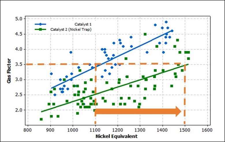
Figure 1. Gas Factor versus Nickel Equivalent
Antimony (Sb) injection can also be utilized to offset the harmful effects of Ni. Industry data suggests that typical refiners start to use Sb at nickel levels of 1,000 ppm (Figure 2).
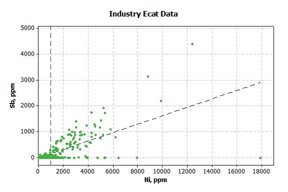
Figure 2. Industry E-Cat Data: Sb (ppm) versus Ni (ppm)
Vanadium can also become an issue when processing resid because it destroys zeolite and increases the production of coke and dry gas. Vanadium takes the form of vanadic acid, which is volatile in the regenerator; and as a result, it is mobile. Vanadic acid is a strong acid that destroys zeolite by hydrolysis of its silica/alumina framework. Vanadium also acts as a dehydrogenation catalyst; however, the dehydrogenation activity of vanadium is roughly one-fourth that of nickel. It is advantageous to trap the vanadium into an inert form. Grace uses an integral rare-earth trap technology, which has proven to be very effective for controlling vanadium poisoning. The rare earths are “basic” oxides and can react with vanadic acid, trapping it and preventing reaction with the zeolite to reduce the harmful impact of the metal.
Iron (Fe) and calcium (Ca) are other metals that can pose potential complications when processing a percentage of resid. To address iron and calcium problems, it is crucial to have an FCC catalyst that is designed to resist negative impacts of the metals. High-alumina catalysts, especially catalysts with alumina-based binders and matrices, are best suited to process iron- and calcium-containing feeds because they are more resistant to the formation of the low melting-point phases that destroy the surface pore structure. To avoid experiencing negative impacts due to these metals, refiners should evaluate switching to a more iron/calcium-resistant catalyst and may also consider higher catalyst addition rates to flush the metals from the system.
One catalyst strategy that can be implemented in conjunction with catalyst reformulation is the use of purchased e-cat as a flushing media. Purchased e-cat will need to be evaluated to ensure that it is the proper quality for a resid application. If available, a purchased e-cat with low metal content and the proper zeolite-to-matrix should be selected as a flushing catalyst. It can be challenging to identify a suitable e-cat, since many e-cats available for purchase are from VGO units whose catalysts are not designed to handle resid feedstock.
To prepare for the increased metals loading and the anticipated increase in total catalyst additions, it is important to assess the capability of your catalyst transfer and loading systems to handle the higher rates of solids.
Another specific challenge is targeting the proper catalyst activity for the new mode of operations. Regenerator temperature typically increases when processing a percentage of resid. To stay within regenerator temperature limitations, fresh catalyst activity will need to be reduced to allow for increased catalyst additions to purge contaminate metals.
Another change that will need to be considered is the catalyst design. The catalyst needs to be formulated to improve bottoms cracking while maintaining superior coke selectivity, which will help offset the higher bottoms yield. Optimum pore volume, pore size distribution, and zeolite-to-matrix ratio are crucial to optimizing bottoms cracking and coke selectivity. It is recommended that you have a discussion with your catalyst supplier to ensure that you are receiving the optimum catalyst for the new mode of operation.
In addition to catalyst changes, operational changes will also need to be considered when processing resid. Regenerator temperature may become an issue and can be addressed by reducing riser temperature, reducing feed rate, or, if available, adjusting catalyst cooler duty.
Decreasing feed preheat is another option that can be considered, but feed nozzle operations should be monitored when making adjustments to preheat. The minimum feed temperature while processing resid could be different than processing vacuum gasoil. Understanding this minimum feed temperature is important for ensuring proper feed atomization. There can be a point where regenerator temperature increases instead of decreases when feed preheat is decreased. If this occurs, it will indicate that the feed atomization is not adequate at the set feed temperature. This is illustrated in Figure 3.
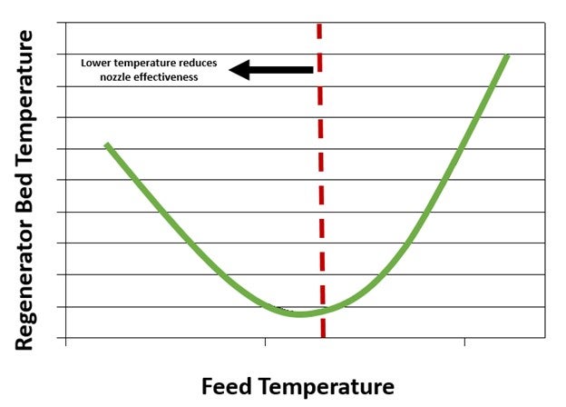
Figure 3. Regenerator Temperature as a Function of Feed Temperature
In conclusion, it is critical to understand the quality, consistency, and quantity of the resid that will be processed in the unit. This knowledge is needed to create a well-thought-out catalyst and operating strategy for successfully processing resid in the unit.
SANJAY BHARGAVA (KBC Advanced Technologies)
Process changes center around maintaining conversion due to higher delta coke resulting from higher Concarbon resid processing and the combustion air requirement. In the absence of a redesign of feed nozzles, naphtha recycles, a cat cooler, or two-stage regenerators, the process changes we recommend include higher dispersion steam to minimize high regen temperature to maintain cat-to-oil ratio and conversion. The other change that would allow resid processing would be to evaluate FCC-friendly crudes that are more paraffinic, and which have low metals and low Concarbon to allow for economical operation. Resid processing will increase fouling in exchangers as a result of asphaltene deposition in the slurry exchangers.
Catalyst changes and using additives together is an efficient way to allow for resid processing without expensive capital investment and allows for the flexibility of returning the operation back to gasoil cracking, as economics permit. The addition of resid increases the average size of the molecules, requiring a more active matrix with a larger average pore size for enhanced bottoms cracking (similar to the addition of a bottoms cracking additive if the base catalyst is not changed). The addition of resid also needs more metals-resistant catalyst to counter the effect of higher coke and gas due to higher Ni, V, and possibly Na in the feed, in spite of higher cat additions to maintain MAT activity. More coke and gas selectivity assists in reducing the deleterious effect of higher coke make tendency of resid feeds due to both higher Concarbon and the more refractive nature of the resid feeds. Catalyst additives, besides naphtha recycle, can also be used to reduce SOx by 15 to 30%. Bigger changes will need feed pretreatment and/or flue gas desulfurization.
REBECCA KUO (BASF Corporation)
If an FCC unit that typically runs gasoil starts to process a percentage of resid, the first step is to analyze the feed properties to understand metals content (particularly Ni, V, Na, Ca, etc.), gravity, and Concarbon (Conradson carbon). If possible, input these new feed properties into a kinetic model – such as FCC-SIM – to understand the impact on yields and conversion. If there will be a large amount of Concarbon in the feed, leading to higher delta coke, the model is useful to see which handles can be used (such as riser outlet temperature, feed temperature, or feed rate) to lower the delta coke within unit constraints. A long-term strategy is to reformulate to a lower delta coke (more coke-selective) catalyst. If there will be a larger number of metals that lower activity (such as V, Na, or Ca), a short-term mitigation strategy is to increase the catalyst additions (whether fresh or purchased) to dilute the metals in the circulating inventory. If the refinery plans to process this higher amount of resid for a longer amount of time, another strategy is to reformulate the fresh catalyst to a higher activity [through higher SA (surface area) and/or REO (rare-earth oxides)] to counteract the loss in activity. Refiners can also use V (vanadium) traps, either loaded separately as an additive or pre-blended into the catalyst formulation, to trap vanadium and prevent activity loss. If there will be a larger number of metals (such as Ni) that cause dehydrogenation reactions, a short-term mitigation strategy is to inject antimony (Sb) into the feed. However, while Sb is very effective at passivating Ni, it can cause NOx emissions or bottoms fouling to increase in certain scenarios. Many refiners also do not have the capability to inject Sb. A long-term mitigation strategy is to reformulate to a fresh catalyst that is designed for metals passivation. These technologies include specialty aluminas incorporated within the catalyst particle which passivate Ni and BASF’s Boron-Based Technology (such as BoroCat™ and Borotec™) which uses mobile boron to passivate Ni. If refiners do have the ability to use Sb, it is recommended to combine with a metals-tolerant catalyst as the benefits are cumulative.
MALLER (TechnipFMC Process Technology)
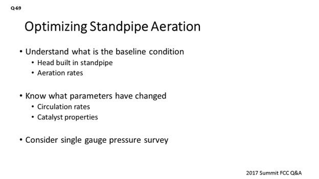
Standpipe stability is highly dependent on the design. Some units do not have any aeration; some units have aeration that they never look at over the run; and some units require constant monitoring on a weekly or even daily basis. So, it really depends upon the design. What we are looking at is the number of head built inside the standpipe and the density through the various sections in the standpipe. It is important to have an understanding of the baseline condition and targets before you run outside and start trying to adjust the aeration.
So, what would prompt a change? If you are going to turn down, you will be looking at lower circulation rates. There is a regime where the standpipe is not going to perform well, wherein the flux rates are about 60 to 100 pounds per second per foot squared. That is the regime where the bubbles are no longer flowing downward. They start wanting to flow upward and coalesce into bubbles that are large enough to start affecting the catalyst flow.
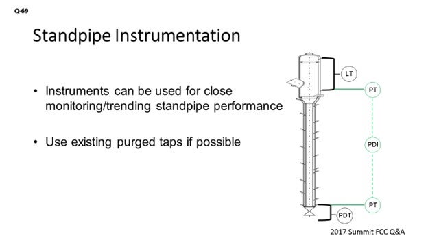
What I like to do is monitor the pressure profile all the way down to the standpipe, with a single-gauge survey on various intervals, to get a good understanding of how it should be performing. You should be able to use the aeration taps to measure the process pressure inside the standpipe. You can take a pressure reading on each one of the taps and make a map plotting the height elevation of that tap versus the measured pressure.
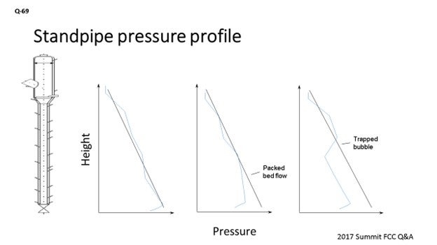
What a well performing standpipe will show is more or less a linear increase in pressure as you go down on the same pipe. Seeing areas where you are not getting the pressure being built up as much as it is in other areas could be an indication that you will want to adjust the aeration in that area. Also, seeing areas where you have pressure drop in the standpipe can be an indication that you are putting in too much aeration. Some FCC units that have really finicky standpipes have installed purged taps with pressure transmitters down the standpipe in order to monitor this profile online. That may be a good option if standpipe stability is a major concern. That way, everything is recorded so you can go back into the historian to see trends so you will be prepared for future standpipe performance.
If that is not possible, you can always look at the instruments you do have available. A standpipe will typically have some kind of level instrument on the upstream side of it. There should be purged tap there. You can either use an online calculation in the DCS (distributed control system) to get a pressure reading at that location, or you could put in a dedicated pressure transmitter instrument which would piggyback on that existing tap. Then, do the same on the upstream side of the slide valve to get the pressure reading directly above the slide valve. You would then have an online measurement of what the head is being built in that standpipe, independent of what is happening on the downstream side of the slide valve.
TRAGESSER (KBR)
Alex did a good job of answering the question. I will just add a more high-level comment. The overall goals of a FCC standpipe are to transfer catalyst from one vessel to the other and to help ensure that the slide valves or plug valves are operating within a reasonable range and have a steady dP to ensure a steady flow of catalyst. Since we are in Austin, I think a quote from Darrel Royal may apply here. He used use to say, “When you throw a pass, three things can happen and two of them are bad.” I think the same applies to adjusting standpipe aeration: The potential outcomes could be that 1) nothing will change; 2) it may get worse; and 3), you could get lucky and it might actually improve. So, if you have good steady slide valve dPs, it is not recommended to try and make it better.
I would like to mention one thing related to the standpipe: In order to have a standpipe with a good pressure buildup, it is important for the catalyst to be properly fluidized before entering the standpipe. If it is not well fluidized when it leaves the cone, there is not much that can be done to correct this problem in the standpipe and it will be a frustrating exercise to try. Depending on the design, there may be fluidization in the cone that will need to be set properly for this to occur.
FEDERSPIEL (W.R. Grace & Co.)
I agree with what has been said. I just want to touch on the catalyst contribution to standpipe aeration. Not only do changes in operating conditions, feed rates, and fluxes prompt an evaluation, changing the catalyst type should probably also prompt that same evaluation. The graph on the slide is demonstrating this maximum stable expansion ratio: a ratio of the density for incipient fluidization over the density for incipient bubbling. It really gives you a window of a healthy operation. As we go through standpipes, we are compressing the catalyst flow and changing the circulating density. What we see here is not just the average bulk density; it is actually a proxy for particle density. It plays a role in that maximum stable expansion ratio, but the fines content does as well. So, anytime you run into an issue where you might be losing fines material, it is likely that you will probably need to go out and adjust the standpipe aeration because it might be moving the window of your healthy operation.
J.W. “BILL” WILSON (FCC Consultant)
All of these comments are good. I want to add one more that was prompted by the statement said about optimization. I think the best rule for dealing with standpipes is: If it is not broken, do not fix it. As Steve said, there are three things that can happen, and two of them are bad. More often than not, the two that are bad will happen when you are playing around with the standpipes. By being ‘not broken’, I mean that you are getting adequate pressure buildup in the standpipes. So, if you have good pressure drop across the slide valves and that pressure drop is stable, do not fix it. So, if you are not getting the most delta, the most apparent density, or the most pressure buildup you can out of the standpipe, who really cares if you are getting enough? You can spend a lot of time going from a 35- to a 40-lb/ft3 (pound per cubic foot) apparent density in that standpipe and gain absolutely nothing, in terms of unit operation, and greatly increase the chances that somewhere in the process you will shut down the unit.
ZIAD JAWAD (Phillips 66)
I think one of the biggest problems with troubleshooting standpipes is the fact that the taps are not accessible. So, it is important that during the turnaround, when you have access to those taps, make sure that the root valves are working and not plugged. When you go through your inspection, stick a wire rod through just to make sure you actually have a tap you can work with during the run if there is a problem.
ALEX MALLER (TechnipFMC Process Technology)
Standpipe aeration is something which has been studied and reported on since the inception of cat cracking. Some standpipes require no attention and may not even have any aeration provisions provided. Others may be so sensitive to changing conditions that adjusting aeration is a daily action. Standpipe design is the most important factor. They tend to be very sensitive to changing direction, such as going from vertical to slanted.
The operational changes that would prompt a review of the standpipe performance are changes in catalyst circulation rate. Standpipes tend to not perform well in a certain range of catalyst flux, where the bubbles formed by the aeration flow neither down nor up. Instead, they coalesce together until they are large enough to have buoyancy to flow in the upward direction. These large bubbles can block the catalyst flow and are a source of instability in the slide valve dP. The range of catalyst flux which is to be avoided is generally 60 to 100 lb/ft2/sec (pounds per square foot per second).
An important aspect to monitor when reviewing standpipe operation is the pressure profile in the standpipe. Some units have dedicated, purged, pressure instruments along the standpipe for this purpose. Another option is to consider a pressure instrument on the aeration tap to give an indication of the pressure inside the standpipe. Most units just use the slide valve dP to indicate standpipe performance as the downstream pressure is usually constant; therefore, any variance in dP is changes in the head being built in the upstream standpipe. One suggestion is to consider a pressure instrument that piggybacks off the upstream slide valve dP tap. This pressure transmitter would give a direct reading of the pressure at the base of the standpipe. Having the same type of pressure tap upstream of the standpipe, such as on the high pressure tap of a level instrument, will give a direct reading of the standpipe head being built.
Regardless of your instrumentation arrangements, it is important to take regular single-gauge pressure surveys to understand the baselines for standpipe performance. These surveys should be taken at multiple elevations down the standpipe. If taking a reading off of an aeration tap, ensure that the aeration air is temporarily throttled to ensure that the backpressure through the tap is not impacting the pressure reading. An area in the standpipe where no head is being built is an indication that aeration adjustment may be warranted.
Although it is important to ensure standpipe fluidization over all modes of operation, when standpipes are not stable, operators have a tendency to want to increase the aeration rates to the taps. Overaeration of a standpipe can show similar symptoms as an underaerated standpipe. Both should be avoided. Establishing a good baseline of proper standpipe performance will help to give you a better idea of which direction to turn the valve when adjusting aeration of a finicky standpipe.
MICHAEL FEDERSPIEL (W.R. Grace & Co.)
Standpipe aeration is provided to replace the volume of gas lost in a fluidized catalyst as head pressure builds and compresses the gas. Not all standpipes have provisions for aeration; usually those without aeration taps are short in length and have minimal change in direction. Longer standpipes require aeration to ensure the smooth circulation of catalyst and sufficient slide valve delta P.
To calculate how much aeration a given standpipe requires, the first step is to calculate the volume of circulating catalyst emulsion (VEmulsion).
VEmulsion = QCatalyst/ρEmulsion
VEmulsion is used to calculate the volume of gas circulated with the catalyst.
VGas = VEmulsion * (1 – ρEmulsion/Skeletal Density)
The next step is to calculate the absolute pressure at the inlet to the standpipe and at each aeration tap location.
PInlet = PDilute + ρEmulsion * ΔH where ΔH is the distance from the inlet to the top of the bed
and
PTap = PInlet + ρEmulsion * ΔH where ΔH is the distance from the tap to the inlet
Finally, the calculated terms VGas, PInlet, and PTap are used to compute the change in gas volume due to the increased pressure.
ΔVGas = VGas – (VGas * PInlet)/PTap
ΔVGas is the theoretical amount of aeration required at each tap. Note: Each tap must be calculated individually, and experience shows the actual aeration requirement is usually 30% lower than theoretical.
Large changes in catalyst circulation rate, bed density (emulsion density or ρ in the calculation above), or system pressure should trigger an optimization of standpipe aeration. Additionally, if any taps along the standpipe were to become plugged with catalyst, the surrounding taps would need an adjustment.
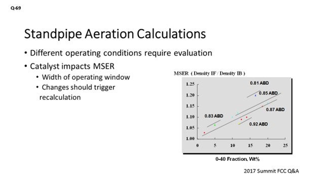
Although the skeletal density of different FCC catalysts is usually very similar, changes in catalyst can impact the emulsion density and pressure profile and require aeration optimization. Catalyst properties (along with aeration medium) also sets the maximum stable expansion ratio (MSER), which is defined as:
MSER = Catalyst Density at Incipient Fluidization/Catalyst Density at Incipient Bubbling
The MSER indicates the “width of the operating window” over which a bed of fluidized catalyst is well-behaved. In the context of a standpipe, the MSER indicates how much a fluidized bed can be compressed before it will revert to a packed bed (defluidizes). The MSER is a function of catalyst particle density (with ABD used as a proxy) and 0-40 fines content, as shown in Figure 1.
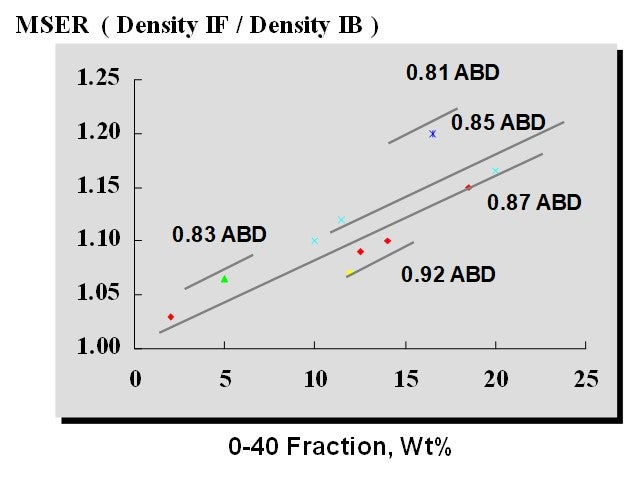
Figure 1. Maximum Stable Expansion Ratio at Different Catalyst Properties
Monitoring the physical properties of the FCC catalyst is an important part of standpipe aeration optimization. Changing catalyst types should cue an evaluation of the standpipe aeration. Taking a single-gauge pressure survey of the standpipe can give valuable insight into the condition of the standpipe’s aeration. This survey is especially important to do while the unit circulation is healthy in order to establish a baseline, as shown in Figure 2.
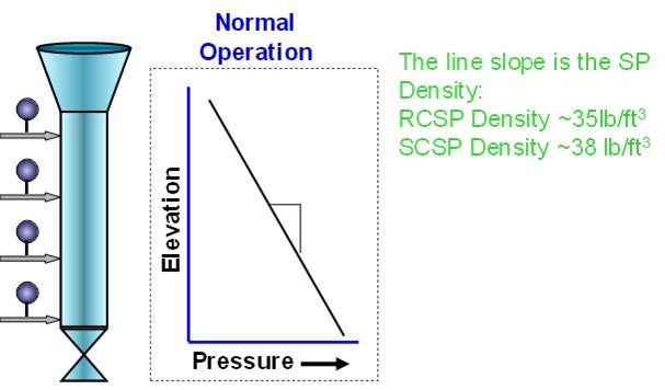
Figure 2. Typical Standpipe Pressure Profile
Pressure profiles, like those in Figure 3, indicate it is time to adjust standpipe aeration.
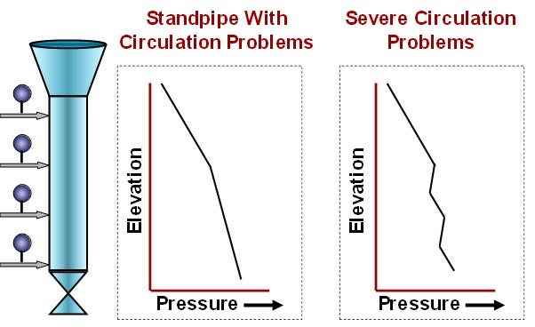
Figure 3. Abnormal Standpipe Pressure Profiles
Finally, monitoring slide valve delta P is another method of tracking standpipe aeration. If the slide valve delta P unexpectedly changes or becomes erratic, the standpipe aeration should be reviewed.