
Question 89: In shifting from partial burn to full burn in a side by side unit, what has been your observed impact on the NOx emissions? What is necessary to achieve 20 ppm NOx?
David Hunt (Grace Davison)
Several Grace customers successfully operate with NOx emissions less than 20 ppm in full combustion without the use of NOx removal hardware in the flue gas circuit.
These units have the following common theme:
•Regenerator Flue Gas excess O2 levels are less than 1.5 vol%.
•If necessary, a non Pt combustion promoter like Grace’s CP® P is used to control afterburn and/or CO emissions. Additions of promoter are minimized since excessive additions of any CO combustion promoter can increase NOx.
•Some of these units inject ammonia into the flue gas stream to meet NOx limits.
•Some of these units use a NOx reduction additive such as Grace’s DENOX®.
•The regenerator combustion air and spent catalyst are extremely well mixed.
Year
2010
Submitter
Process
Question 90: Does any refiner use an on-line particulate emissions (PM) analyzer to measure PM concentration and/or particle size distribution in the flue gas? Are any of these analyzers using continuous emission monitoring systems (CEMS)? How reliable and accurate have these systems been?
Emerson Domingo (Sunoco)
Sunoco currently has a particulate matter (PM) analyzer in one location on the stack of a Wet Gas Scrubber. It is there to measure Filterable PM only, not particle size distribution. This was installed as a requirement of a local environmental permit. In general, the permit required that a PM analyzer be installed on a trial basis and collect data for a period of months and compare the results to stack testing data. During this trial period the analyzer is not considered a CEM. Afterwards, if the PM analyzer data is found to be representative of actual PM emissions, then the PM analyzer could be deemed as a CEM.
During the trial period, Sunoco has conducted several stack tests, representing a full range of emission concentrations for which there were no unit issues and no analyzer issues. The testing represented a wide range of unit rates and PM emissions. Sunoco has found the PM analyzer data to be inconsistent with stack testing data taken. Since then, Sunoco has been asked to work directly with the PM analyzer vendor to verify these initial findings.
Year
2010
Process
Question 91: Assuming the FCCU already has a third stage separator, what are the various options you consider for further reduction of particulate emissions (PM) and what is the expected level of PM to be achieved?
Steve Shimoda (SHAW)
The first thing to consider is the fourth stage collector. For designs that re-introduce the collected fines downstream of the expander, a fourth stage collector with fines removal and filter on the TSS underflow gas will aid in reducing PM. Additional measures that can be taken include adding an electrostatic precipitator or a flue gas filter. In one of Shaw’s licensed units, a flue gas filter was added downstream of the waste heat boiler and has been successful in reducing the particulate emissions since 2004. This system has been robust in that it was able to capture large excursions due to upsets in the regenerator. Particulate emissions also are reduced when a wet gas scrubber is installed, though generally for a different reason. Some typical PM values are:
•ESP (<100 mg/Nm³)
•Wet Gas Scrubber (<50 mg/Nm³)
•Flue Gas Filter (<10 mg/Nm³)
David Hunt (Grace Davison)
Many FCC units which use third stage separators operate with particulate limits <1 lb/1000 lb of coke burn. The absolute PM emission will depend, of course, on unit conditions such as the design characteristics, cyclone velocity, unit pressure and particulate loading of the third stage separator.
To ensure low emissions from a third stage separator, an exhaustive review of the following FCC operations should be confirmed:
1.No excessive catalyst attrition sources are present: a.Vapor velocities should be less than 300 fps and preferably less than 100 fps b.Restriction orifices are present and the correct size c.Torch is not being used
2.Regenerator Cyclone velocities are within acceptable operating limits.
3.Regenerator Bed Level should provide the correct burial requirements for the cyclone dipleg valves, and the transport disengaging zone should terminate below the cyclone inlet.
4.Secondary Cyclone dipleg levels should terminate well below the top of the dipleg (3ft).
5.All steam sources are dry.
6.Regenerator superficial velocity is minimized.
7.Regenerator air and spent catalyst distribution is adequate to ensure the diplegs terminate in well fluidized zones and each primary cyclone has similar catalyst entrainment.
The catalyst design can also be optimized to minimize particulate entrainment to the third stage separators to ensure maximum third stage separator efficiency.
Catalyst attrition is likely the most important catalyst property to consider; however, consideration of the amount of micron fines (<1 micron) generated during catalyst attrition is more important.
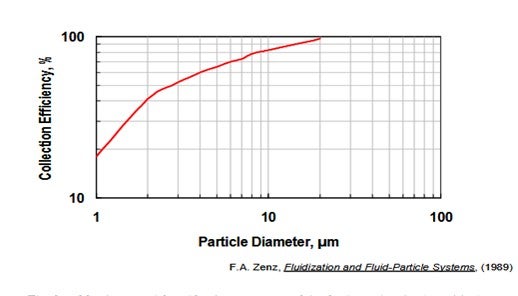
The figure below confirms that the cyclone efficiency falls by almost a factor of 10 for a 20-micron particle versus a 1-micron particle. As a result, two catalysts which have the same attrition index can have much different particulate emissions, depending on whether micro fines are generated during attrition versus particles in the 5-to-20-micron range.
Cyclone Efficiency vs. Particle Diameter
The 0 to 20 micron and 0-to-40-micron content of the fresh catalyst is also critical to ensure low particulate emissions from a third stage separator. These particulate fractions should be minimized within the constraints of the catalyst circulation system. (Many units need higher fresh fines content to ensure stable catalyst circulation.)
A catalyst with a higher particle density, not necessarily higher apparent bulk density, will increase TSS efficiency. Al2O3 content can be used to increase the particle density.
An article entitled Optimizing your FCC Regenerator Operation and Catalyst Design Can Minimize Catalyst Losses provide a detailed review of many of the issues discussed above. (1)
Grace recommends our Al-Sol catalysts such as ALCYON®, IMPACT®, GENESIS®, AURORA®, and AdVANTA® for units which use third stage separators. Worldwide, Grace supplies more FCC units with third stage separators than any other catalyst supplier. While we are the world’s largest supplier of FCC catalyst, our market share of units using third stage separator devices is even larger. This market advantage is a testament to the fundamental advantage of Grace catalyst and our Al-Sol catalyst, in particular, for minimizing emissions from third stage separators.
1. Hunt, et. al, “Optimizing your FCC Regenerator Operation and Catalyst Design Can Minimize Catalyst Losses”, Catalagram® 90, 2002.
Year
2010
Submitter
Process
Question 33: What downstream processing issues have been associated with the overfeed of NaOH at the crude unit?
Caustic is injected with the crude charge on some units to reduce chlorides in the crude overhead system and impact the salting and corrosion potential.
Year
2019
Process
Question 35: What is the importance of sodium to reliability in the coker? What are some of the potential sources of the sodium in coker feed? In light of IMO how should sodium be managed in purchased coker feed?
DENNIS HAYNES (Nalco Champion, an Ecolab company)
Sodium in the coker feed can be introduced via sodium content of the salts in crude, caustic addition at the crude unit for corrosion control purposes, as a contaminant in recovered oil material in the refinery, sodium content of other purchased feedstocks (as mentioned in the question) among others. Elevated sodium levels in the feeds will increase fouling of the Coker furnace. Potential solutions are enhanced dehydration of slops, crudes, or feedstocks where possible in tankage, improved reliability and optimization of crude unit caustic feed rates via addition of caustic blend tanks for improved control of strength and also automation of overhead chloride analysis tied to caustic feed pumps, optimization of the crude unit desalting process, and addition of heavy oil desalting for imported feeds.
Year
2019
Process
Question 37: With higher anticipated charge rates at the coker due to IMO, what are your best practices around defoamer application to minimize impact on hydrotreater catalyst life?
STEVE WILLIAMS (Marathon Petroleum Corporation)
- As equipment ages and reaches end of useful life, the opportunity arises with necessary replacement to include enhancements or upgrades at little additional cost.
- Since the only cost associated with an upgrade, in these cases, would be any incremental cost of the upgraded components, the associated capital cost is significantly reduced and makes for a prime opportunity to obtain performance enhancement.
- However, the key to successfully identifying and capitalizing on these opportunities is an integrated, multi-functional team-based approach to work scope identification and planning to ensure that upcoming opportunities are realized far enough in advance to allow for the engineering and procurement associated with the upgrade scope.
- Failures to capitalize on equipment replacement activities as opportunities to affect performance enhancements, resulting in simple replacement in kind, are typically the result of late realization of the planned work.
- Typical project economics and justification, such as increased throughput or product recovery, are suitable, and can typically be applied to the incremental capital costs of the upgraded components only.
- Presentation will include specific examples where this approach has been successful.
Year
2019
Process