

Question 6: The use of infrared pyrometers for monitoring tube temperatures in steam reformers is a well known practice. What is your recommended frequency for use of these devices ( how many times per week)? Can you offer any recommended alternate devices or methods available such as fixed infrared pyrometer skin thermocouples or infrared imaging?
Brian Slemp (CITGO)
CITGO’s operating philosophy is to monitor our tubes with an optical pyrometer every shift. We monitor the tubes from multiple locations on each level of our terraced wall furnace. This method has been extremely effective in extending the life of the furnace tubes and catalyst. The original load of catalyst lasted in excess of 15 years and the original tubes were in service nearly 20 years.
I am unaware of any alternate devices used for this purpose at this time. A vendor has identified an experimental effort to insert a new technology, internal tube temperature. This technology may provide more reliable continuous temperature monitoring.
Praveen Gunaseelan (Vantage Point Energy Consulting)
The typical monitoring frequency with hand-held infrared (IR) pyrometers is at least once per shift during normal operation. Additional monitoring beyond this would be needed during abnormal operating scenarios. Due to differences in steam reformer designs, it is prudent to consult with your technology provider or their recommended engineering contractor for specific recommendations on this issue.
The alternate approaches mentioned are useful to supplement hand-held IR monitoring.
•IR imaging (camera) is useful for screening broader sections of the furnace at a time, and can help to identify potential concerns for more detailed follow-up with hand-held IR pyrometers.
•Skin thermocouples have a reduced life in SMR furnaces due to the high temperatures, and are thus not used as a primary method for monitoring. When functioning, they are relatively accurate and useful for remote monitoring.
•Fixed IR pyrometers are potentially useful for continuous monitoring of a specific location.
Randy Peterson (STRATCO)
The isobutane recycle sample can be neutralized at the sample location using a chamber filled with alumina or KOH pellets. If using a KOH chamber, it is best to add a filter downstream to filter out any fines.
Alternately, the sample may be neutralized in the lab upstream of the GC by the same method. In some refineries, KOH pellets have been added directly to sample bombs prior to sampling.
The iso recycle from the side draw of an isostripper typically contains about 1% HF. However, if the tower is refluxed and the iso recycle stream comes from the tower accumulator, the sample may contain more HF.
Josh Siegel (Johnson Matthey Catalysts)
The tubes in a steam methane reformer (SMR) operate close to the limits of materials technology. Stresses induced as a result of very high temperatures, combined with large differential pressures across the tube, mean that tubes undergo irreversible creep and therefore only have a limited life before they fail. Operation at tube wall temperatures significantly above design can result in a rapid increase in the number of tube failures. Inversely, an operator wants to avoid operating a reformer with tube temperatures below design will result in the full capacity of the reformer not being realized. An operator must therefore have confidence in the temperatures measured.
If the hydrogen plant is running at a fixed rate, then tube wall temperature measurements are generally taken for maintenance purposes anywhere from once a week to once a month. This frequency of measurement allows data for tracking tube wall temperatures over time and to verify that design conditions are not exceeded. Typically the measurements would be taken when the plant is running at high rates, as this is normally when the tubes would exhibit their hottest temperatures. For reformers in which the tubes are running hot, have hot spots, giraffe necking, or another indication that something is causing non-optimal operation, we recommend more frequent measurements. When these conditions are present, it is good practice to conduct spot checks once per shift to keep an eye on the known hot spots in the reformer. During times where the plant is ramping up and down in feed rates or changing feedstocks, it is also a good idea to do spot checks to ensure no heat imbalances or hot spots exist.
While infrared pyrometry for monitoring tube temperatures in SMRs is a well-known practice, it is important to understand the proper methodology of measuring the tube temperature as well as understanding what effects the readings. Infrared pyrometers read the level of radiation from a target that, in this case, would be the SMR tube. However, the tubes in a SMR receive other radiated energy within the reformer. This radiation can be from sources such as the refractory, flames, or even adjacent tubes. In order to account for this extra radiation, the proper background corrections need to be performed to get an accurate tube wall temperature measurement. If no background correction is used, temperatures close to 60°F higher than actual temperatures can be measured for a top-fired reformer. For a side-fired reformer, the reading can be up to 90°F higher.
Laser pyrometers are also used for tube wall temperature measurement. Laser pyrometery operates by sending out a low powered pulsed laser of known energy at the target. The return signal is detected with a conventional infrared signal to quantify the background radiation. To fully account for the background radiation this method requires impact of the target to be at right angles. This is not achieved with cylindrical reformer tubes, creating some concern about the accuracy of the measurements. This error in measurement can contribute to a high estimate of the target temperature.
Manual infrared imaging has been receiving much more attention over the last decade. This imaging does allow good trending analysis of SMR tubes, in that it is able to see multiple tubes in the image at one point in time compared to the more targeted analysis of a pyrometer. This trending enables awareness of hot and cold areas of the reformer as well as tube wall temperatures at a single point in time. Technology also exists where infrared imaging cameras are installed on the reformer providing a live feed to the control room. This technology has provided value during transient and start-up conditions, a time where severe tube damage is most likely to occur. Operators can see the burners and their flame patterns without being on the reformer. With both types of infrared imaging, it is still difficult to correct for the radiation effects, so the temperatures measured are a high estimate.
One technique that can be used for measuring tube wall temperatures that eliminates the background radiation is a Gold Cup pyrometer. The Gold Cup pyrometer is an infrared radiation detector on a water-cooled probe that is placed squarely on the tube thus eliminating the reflected radiation. While this technique provides very accurate tube wall temperature measurements, it is limited by line of site access from the reformer portholes. In addition, it is labor intensive requiring a practiced team of two operators.
Skin thermocouples provide a continuous measurement of tube wall temperatures. Skin thermocouples, when installed correctly, can give accurate tube wall temperatures, however, under typical conditions they have been known to have short and unpredictable lifetimes. Another issue for skin thermocouples is how they are attached to the tube. If the tubes are slotted to attach the thermocouple it weakens the tube wall. One way to get around this would be spray welding. However, this technique has a drawback in that it will not provide an accurate indication of the tube wall temperature at much above 1,100°F.
Monitoring of tube wall temperatures is an important practice. Tube wall temperature measurement should be a weekly part of plant monitoring, increasing in frequency as the severity or performance of the SMR dictates. Infrared pyrometers are the most well-known means of conducting tube wall temperature measurements. However, the accuracy of those measurements requires background radiation correction. Gold Cup pyrometry provides accurate tube wall temperature measurements, but is laborious in its technique. Correction methodologies for infrared pyrometry provide a means to get close to Gold Cup measurements. Alternative technologies are available for use and while providing good qualitative results, still need improvement to address the accuracy of the temperature measurements.
Year
2010
Submitter
Process
Question 7: What is your experience with reusing molecular sieves in pressure swing adsorption hydrogen purification? What is your recommended inspection criteria for the molecular sieve to be reloaded?
Brian Slemp (CITGO)
CITGO has successfully reloaded the same PSA adsorbents multiple times in the same PSA skid.
We review operating history to ensure the system was not exposed to a significant amount of liquid water carry over. We monitor the hydrogen recovery from the PSA and ensure the system is operating within the design parameters to determine if the adsorbent is worth retaining. The material is carefully vacuumed from the vessel to minimize cross contamination of the layers. The adsorbent is screened with an inert system to minimize moisture adsorption and stored in a location protected from the elements in sealed metal containers.
Vern Mallett (UOP)
The Molecular sieve adsorbent is routinely reused when vessels are unloaded for routine vessel inspection. The adsorbent must be screened, segregated from other adsorbent, and stored such that it is protected from exposure to ambient air. Typically, 15-20% fresh molecular sieve is required to make up for losses during the unloading/loading activities. A LOI (Loss on Ignition) test can be performed to test the molecular sieve activity. Finally, if the PSA unit was not meeting the design performance prior to the unloading, then reuse of the molecular sieve is not recommended
Dan Webb (Western Refining)
We don't have any experience with these however I have heard from others in the industry that the mole sieves give relatively few problems. The mole sieve would likely only be dumped when the vessels are due for internal inspection. The alumina should be replaced as a precaution along with the activated carbon. as for the mole sieve material it would be intermixed with the other products due to the dumping procedure. The mole sieve and other components to a PSA vessel are fairly cheap and the cost of replacing them is likely not worth the risk of operational issues associated with not replacing them.
Randy Peterson (STRATCO)
Oxygen is a major cause of monel denickelfication. Oxygen can enter the circuit during loading operations. Care should be taken to avoid pressuring air contained within loading pipes/hoses into the unit. Whenever monel is overlayed on carbon steel, a “butter” layer of nickel should be laid down prior to the monel layer. This step reduces the potential of a poor-quality overlay. A corrosion problem has been reported with packed regenerators using monel rings. Due to distribution problems commonly associated with packing, portions of the packed beds run dry and hot. The monel tends to severely corrode under these conditions leaving only a copper residue. Although packed regenerators typically work well when first commissioned, trayed regenerators tend to have less corrosion over time as the trays are kept cool by the flowing liquid. Therefore, fixed valve trays are recommended in this service. Chase Homen (El Paso Refinery) We don't have any experience with these however I have heard from others in the industry that the mole sieves give relatively few problems. The mole sieve would likely only be dumped when the vessels are due for internal inspection. The alumina should be replaced as a precaution along with the activated carbon. as for the mole sieve material it would be intermixed with the other products due to the dumping procedure. The mole sieve and other components to a PSA vessel are fairly cheap and the cost of replacing them is likely not worth the risk of operational issues associated with not replacing them.
Randy Peterson (STRATCO)
Oxygen is a major cause of monel denickelfication. Oxygen can enter the circuit during loading operations. Care should be taken to avoid pressuring air contained within loading pipes/hoses into the unit.
Whenever monel is overlayed on carbon steel, a “butter” layer of nickel should be laid down prior to the monel layer. This step reduces the potential of a poor-quality overlay.
A corrosion problem has been reported with packed regenerators using monel rings. Due to distribution problems commonly associated with packing, portions of the packed beds run dry and hot. The monel tends to severely corrode under these conditions leaving only a copper residue.
Although packed regenerators typically work well when first commissioned, trayed regenerators tend to have less corrosion over time as the trays are kept cool by the flowing liquid. Therefore, fixed valve trays are recommended in this service.
Chase Homen (El Paso Refinery)
We don't have any experience with these however I have heard from others in the industry that the mole sieves give relatively few problems. The mole sieve would likely only be dumped when the vessels are due for internal inspection. The alumina should be replaced as a precaution along with the activated carbon. as for the mole sieve material it would be intermixed with the other products due to the dumping procedure. The mole sieve and other components to a PSA vessel are fairly cheap and the cost of replacing them is likely not worth the risk of operational issues associated with not replacing them.
Year
2010
Process

Question 8: With respect to hydrogen purification pressure swing adsorption vessels, what are the best practices regarding inspection? Can their working life be extended beyond design with vessel inspection?
Vern Mallett (UOP)
The intent of a thorough vessel inspection would be to assure that the effects of corrosion, fatigue service, or other operating conditions have not deteriorated the integrity of the vessel. The inspection would determine if the vessel wall thickness has been reduced below the minimum required, or if cracks have developed in any vessel parts. The priority for determining fatigue related cracks would be to inspect the vessel interior, giving special emphasis to the inside weld surfaces. A thorough magnetic particle examination would be highly recommended. We would also suggest checking with local authority, code, or plant requirements about permitting continued use.
UOP recommends that PSA adsorber vessels be periodically inspected to determine if cracking or other potentially harmful defects are present. Typical inspection periods customers have used are in the 2-5 year range. The inspections typically concentrate on the inside weld surfaces, although defects could occur anywhere. Inspection methods that are typically used are magnetic particle inspection (MT), ultrasonics (UT), and less frequently acoustic emissions. A wet magnetic particle examination of all weld internal surfaces is the most thorough method.
Performing external UT while the vessels are online can be considered a good screening method. Ultrasonics will detect imperfections that are within the vessel material and can detect most crack indications on the inside surface. UT requires more operator experience than MT and even an experienced operator might not pick up internal surface cracks which are not very long (less than 1/2") or not very deep (less than 1/16"). If an internal surface indication is detected or suspected with UT the refiner then can consider unloading that particular vessel for an internal exam with MT. Note that if an indication is detected by UT you would not know if it was new or an existing flaw unless a baseline UT exam or “fingerprint” had been performed during fabrication.
Additionally, a thorough inspection should reveal the actual minimum thickness of the vessels as well as any defects which would require repair. Actual thickness measurements might verify that there is more material than the original design. This could be due to various "design factors" that would have been used in the original material order (i.e. extra thickness above our specified minimum, round-offs, tolerances being on the plus side, and corrosion allowance that might be reduced).
This method of extending service life has been effectively used by other UOP Polybed™ PSA System owners and in fact it is not uncommon for PSA adsorber vessels to operate trouble free for 20-30 years. If the life of the PSA adsorbers is extended by the above mentioned, it is then recommended that periodic examinations of the vessel be rigorously continued.
We also share with customers UOP’s co-authored ASME paper, “PSA Vessel Technology: An Overview”. This provides a good background of PSA, evolution of our fatigue design, in-service inspection techniques, and repair of PSA vessels.
Dan Webb (Western Refining)
We conduct regular external inspections. The feed to the PSA will be free of water and other corrosive elements except for unit upsets. We do internal inspections as mandated by OSHA regulations. We would have to dump the vessel and perform an internal inspection then reload it, and as stated above we would recommend replacing all of the media.
Randy Peterson (STRATCO)
Fouling in the DIB column is almost always caused by salt deposits. These salts are typically sodium sulfate and sodium sulfite but can also contain calcium or magnesium if the effluent treating water is not demineralized. If these water-soluble salts are present in the DIB feed, the water will evaporate once inside the column leaving the solids behind. The salt deposits are typically found on or near the feed tray.
The long-term solution is to make changes to the effluent treating system. The quickest operational change is to increase the water makeup rate to the system to dilute the aqueous salt concentration. Monitor conductivity in the water effluent and maintain a level less than 5000 μmhos/cm (microSiemens/cm) to minimize salt carryover.
Properly designed and functioning water wash static mixers are very important to wash any salts out of the tower feed. A retrofit of coalescing media should be considered in all effluent treating vessels to minimize carryover of the salt-containing aqueous phase. If the unit does not have a water wash downstream of an alkaline water wash, a water wash coalescer with static mixer should be considered.
Improving the water quality with softer water can also help. However, it is important to note that some refiners have experienced foaming problems in their water washes when using water that is too soft. Mixing a little hard water with the demineralized (soft) water typically solves the problem (40-50 ppm total hardness in the makeup water is a good target).
A quick fix to improve DIB operations while running is to perform an online water wash. Although this carries some risks, several refiners have successfully restored column operations. The typical method is to add water to the column feed. In doing so, the salts fouling the feed tray are made soluble. The salts are then carried away from the feed tray and redeposited on nearby trays as the water evaporates. This is not a permanent solution as the salts typically remain in the column until washed properly off-line. It is best to add the water as close to the tower feed nozzle as possible to avoid stagnant pools of water in the feed line which can lead to corrosion in low points.
Reboiler Fouling
Reboiler fouling is almost always caused by ineffective effluent treating. If the reaction intermediate esters (typically propyl or butyl sulfates) are not decomposed within the treating system, they enter the DIB and travel down the tower. When they reach the hot reboiler, they thermally decompose releasing SO2 while the organic component fouls the reboiler tube bundle. An indication that this is happening is low pH and high iron in the DIB overhead accumulator water draw. The evolved SO2 and water forms corrosive sulfurous acid. A good target pH is 6.5 – 7.5 with less than 10 ppm iron.
To avoid reboiler fouling, an increase in the temperature of the effluent treating water wash temperatures (>120 F) may help break the esters down. Typically, new static mixers, designed specifically for immiscible fluids, are required.
Some refiners report success with online water washing of the reboiler. Either water is directly added to the reboiler hydrocarbon inlet or enough water is added to the feed so that water goes down the column to the reboiler. In many cases, the boiling water breaks up the foulant and sends it downstream. If not severely fouled, the reboiler performance is restored. Care should be taken with the resulting wash water as it will have low pH (1-2) and will contain solids. In severe cases, the tube bundle requires pulling and hydroblasting to mechanically remove the foulant.
Year
2010
Process
Question 9: What experience do refiners have regarding fired heater stainless steel tubes OD/external polythionic acid attacks due to sulfur in fuel gas such as the ones in hydroprocessing units? What criteria are refiners using to decide when to neutralize the external side of the tubes with soda ash during turnarounds?
Vern Mallett (UOP)
UOP’s recommended neutralization procedures follow the recommendations found in NACE RP0170-2004 1.6. It states:
“The need for protection of the external surfaces of austenitic stainless steel and other austenitic alloy heater tubes should be considered when sulfur-containing fuels have been used for heater firing. In many applications, however, combustion conditions do not form the iron sulfide film that is a key to polythionic acid formation. Consequently, many users do not require protection of the external surfaces of austenitic stainless steel heater tubes. It is only when poor combustion practices lead to reducing conditions that it is possible to generate sulfide scales versus oxide scales externally on heater tubes.”
If it has been determined that sulfide scale is present, then the heater tubes can best be protected by maintaining a balanced set of small fires (or pilots, as applicable) in the heater box at all times, even when there is no process circulation.
UOP conducted a survey of several refiners’ neutralization practices in 2009 and found that the majority of refiners did not take any steps to protect the OD of heater tubes when the heater was shutdown. Out of the refiners that do take steps to protect the OD of heater tubes during shutdown, they are divided between running pilot burners and neutralizing with a soda ash solution.
Of the total 13 total responses, 7 conducted no neutralization of the heater tubes, 1 left pilots on in the heater, 3 conducted soda ash solution neutralization, and 2 left pilots on but conducted soda ash neutralization if entering the heater
Dan Webb (Western Refining)
Austenitic stainless steel (300 series) heater tubes should always be protected against if the fuel contains any appreciable about of sulfur compounds. These metal sulfides form polythionic acids (H2SxO6) when exposed to a wet oxygen environment. We recommend that the refinery Inspection department be consulted prior to shut down when 300 series stainless steel is involved.
Austenitic SS become sensitized to polythionic acid attack after long term service at high temperatures 700° to 1300°F. Sensitization describes steel that has formed chromium carbides along the grain boundaries, producing adjacent chromium-depleted regions that are not as resistant to many corrosion mechanisms. Even stabilized SS may become eventually become sensitized to polythionic acid attack although the time required is greater.
Standard practices for avoiding Polythionic acid SCC are fully described in NACE Standard RPO170. But, in general, the best protection is to maintain a dry air free environment during shutdown. If this is not possible the SS should be neutralized with soda ash solution prior to exposure to air. Austenitic SS that will not be opened should be sealed in a nitrogen-ammonia atmosphere.
Example Neutralizing Procedure:
· 5000 ppm anhydrous ammonia should be injected with the nitrogen if the equipment is cooled to within 130°F
· Inert atmosphere should be maintained by using valves, blinds or rigid plastic covers and duct tape.
· 2% soda ash solution (Na2CO3) should be sprayed over 300 series SS, leaving the soda ash residue to remain on the tubes during the exposure to air. 0.5% sodium nitrate solution to minimize chloride stress corrosion cracking if chloride concentration in over 60 ppmw.
· 1.5% soda ash solution (Na2CO3) should be sprayed over the tubes unless the tubes are kept above 300°F. If tube temperatures will be < 150°C for 4-6 hours, soda ash washing is not necessary
Michael Chuba (Sunoco)
Within the Sunoco system for those heaters using stainless steel tubes we do not generally neutralize the external surfaces of heater tubes during temporary shutdowns or turnarounds. The main reason for this is that the conditions in the fireboxes do not favor formation of sulfide scale on the metal surface. This is one of the critical factors for concern over polythionic acid stress corrosion cracking or PASCC.
Since our hydrotreaters are gas fired, sulfur contents are generally low. In addition, we generally operate with at least 3% excess O2. This results in an oxidizing versus reducing environment. In this environment any iron sulfide scale that may form is quickly converted to an iron oxide, with the sulfur being returned to the flue gas and exiting the firebox as SOx. Thus, for reactor charge heaters in the Sunoco system there is little potential for sulfide scale on the tube surfaces to present a PASCC concern; consequently, passivation of tube ODs during unit outages is typically not necessary. We have not experienced any PASCC failures due to tube OD corrosion.
For heaters that operate in a reducing atmosphere (zero excess O2), where a stable iron sulfide scale may form on the tube surfaces, passivation should be consider. Another case where passivation may be required is where the type of fuel burned in the heater (such as heavy fuel oil) may create heavy ash deposits on tube surface. Localized reducing environments at the tube surfaces (under the deposit layer) can restrict the oxidation of the iron sulfide scale during operation making it susceptible to PASCC.
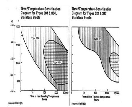
There are other factors that would need to be considered to determine if soda ash passivation of the tube surfaces is needed. The first factor is the tube metallurgy, and whether the heater tubes are a “stabilized” grade of austenitic stainless (such as grades 321 or 347). For these stabilized metallurgy grades the metal operating temperature must be above 850F for at least 1000 hours before the materials would be “sensitized” and susceptible to PASCC. For heaters that have these materials and operate at reduced metal temperatures the soda ash passivation would not be needed even if sulfide scale were present on the tube ODs.
For heaters that operate with metal temperatures above 850F, or the tube materials are from non-stabilized grades (such as grades 304 or 316) then PASCC potential is a concern if the conditions for sulfide scale formation are also present. The final factor to consider in this case is whether moisture will be present inside the fire box during a unit outage. The sources of water can be dew point condensation, rain leakage into the fire box, or any water-washing activities inside the heater. The best method to avoid PASCC is to keep the tubes dry during outages (using dry air purges, N2 purges, space heaters to stay above dew point, etc.). If dry conditions cannot be assured then a sodium carbonate solution should be used to wash (to remove as much ash as possible) and rinse the tube ODs – with the neutralizing residue re-applied whenever it is washed away.
Year
2010
Process
Question 10: What are refiners' experience with respect to unit availability, catalyst performance and product quality when co-processing "renewable" feedstocks in a ULSD unit? Is there a big variation in operability with different sources of renewable feedstocks?
Brian Moyse (Haldor Topsoe)
The co-processing of renewable feedstocks in a ULSD unit means introduction of feed components that are completely foreign to a diesel hydrotreater. These oxygenates will react quite readily with hydrogen to form normal paraffins in the diesel range but in doing so consume high amounts of hydrogen and cause high heat release. In a coprocessing mode these reactions will often occur in the topmost layers of active catalyst. This region will be subjected to low hydrogen partial pressures and high temperature and therefore be prone to increased dP build-up.
Adding to the problem is the existence of numerous contaminants in most ‘renewable’ feeds that will deposit on the grading catalyst layers. This has also been the experience of several refiners that have introduced even small amounts (roughly 5%) of renewable feeds. This actually limited the cycle length as the dP was continuing to increase in co- processing mode. The solution to these challenges are connected to both catalyst and process design. Topsoe has developed a series of biofuels catalysts that have been tailored to ensure gradual conversion of the bio-components and exhibit excellent stability by being able to tolerate higher levels of coke. In one instance, a skimming with subsequent installation of Topsoe tailored grading and biofuels catalysts has eliminated the high dP buildup rate and brought it down to normal “fossil”-operation levels.
Catalyst performance is also closely related to the chemistry of the oxygenate conversion reactions. These produce oxygen containing gases (CO,CO2, and H2O) that may severely inhibit the HDS and HDN activity of certain catalyst types. Even ppm-levels of CO thus decrease the HDS activity of CoMo catalysts by several degrees F, whilst NiMo catalysts are almost unaffected. Gas formation and hydrogen consumption is also related to whether reactions occur by a hydrodeoxygenation or a decarboxylation pathway. The relative usage of these two pathways depends on catalyst type and process conditions.
The main influence on product properties stems from the poor cold flow properties of the normal paraffins produced from the ‘renewable feed’. This will result in higher cloud and pour unless a dewaxing step is introduced. Topsoe markets TK-928 and TK-932, which are sulfidic catalysts that are installed in the bottom of the reactor, in order to improve the cold flow properties with minimum yield loss.
The major component of most tallow and renewable oils is almost always of the triclyeride structure, but may vary in chain length and degree of unsaturation. These differences have implications for product properties and hydrogen consumption.However, it is very important to pay attention to the amount and type of contaminants in these alternative feedstocks because they may severely limit cycle length due to plugging and poisoning of the grading and active catalyst. An effective scheme to remove contaminants is by proper grading design and/or by feed pretreatment to ensure stable operation.
Topsoe has spent a lot of effort in understanding the reaction chemistry and developing catalyst and process technology to handle the challenges of co-processing. Based on this knowledge, the introduction of renewable feeds can in most cases be carried out with no cycle length penalty. This is provided that the proper changes in catalyst loading are made and a moderate unit revamp is carried out. This is especially true for cases where large amounts of coprocessing must be handled. Topsoe has been able to validate the performance of our biofuels catalysts and process design features in industrial operations. We continue to learn from a growing number of references using Topsoe renewable fuels catalyst and technology.
Vern Mallett (UOP)
UOP does not have any direct commercial experience with UOP Licensees co-processing vegetable oils in hydroprocessing units. We have done pilot plant studies co-processing various amounts of vegetable oils with diesel and found that there is significant suppression of HDS reaction rates due to the presence of CO and H2O.
There are several other issues to keep in mind when considering the co-processing of “renewable” feedstocks in an ULSD unit:
1. The olefin and oxygen contents of these feeds are relatively high. This results in increased hydrogen consumption and higher heat release in the reactor.
2. These feeds typically contain free fatty acids, so plant metallurgy must be evaluated to see if it is appropriate.
3. Simple hydrotreating of “renewable” feeds will typically result in an increase in the diesel pour point and cloud point.
4. “Renewable” feed stocks may contain impurities not normally seen in petroleum feed stocks, including phosphorous, sodium, potassium, calcium, magnesium and other impurities. These impurities vary greatly depending on the feedstock source and pretreatment the feed has received. These impurities can have an adverse impact on the hydrotreating catalyst life.
This question was previously addressed at the 2009 NPRA Question and Answer session, question number 70. UOP provided along with other panelists detailed answers to this question.
Praveen Gunaseelan (Vantage Point Energy Consulting)
The reason for co-processing renewable feedstocks such as vegetable and animal fats and oils in refinery ULSD units is to produce diesel that contains a portion of biodiesel, in contrast to blending biodiesel in a subsequent step. Co-processing can have significant impacts on ULSD operation, as outlined below:
· Unit availability:
· Can be impacted if the feed poisons or impairs the activity of the catalyst
· Catalyst:
· Can be rapidly fouled or deactivated
· Produced water can destabilize the catalyst
· Product quality:
· Normal paraffins produced from renewable feeds can impair cold flow properties. An isomerization reactor may be required downstream of the ULSD unit to address this.
· Off-spec product can be generated (because the renewable feed can introduce competing reactions that interfere with the traditional desulfurization and denitrification reactions)
· Impact of feedstock type:
· Can have a variable effect on the life of catalyst, volume of side products, etc.
· Additional pre-processing or post-processing may be required depending on the feedstock contaminants or side products.
Brian Watkins (ART)
ART has conducted testing on various petroleum blends containing between 10-80% renewable sources of feedstock. The catalysts most active for this type of processing are AT580 and NDXi, both premium high activity NiMo catalysts used widely in ULSD and hydrocracking pretreat service. The data show that simple bio-based oils such as soybean, rapeseed & palm oils, when co-processed in a diesel feedstock require essentially the same temperature for 10 ppm product sulfur as the diesel feed alone.Comparing the feeds at ultra low sulfur levels suggests that the co-processing of the renewable oils has a small effect on the performance of the hydrotreater with the variability being about 10°F for <10 ppm product sulfur.
Due to the nature of the renewable sources, a boost in the product cetane index is also observed due to the increase in n-paraffin content in the diesel product. These n- paraffin’s, however, raise concerns about the diesel product cloud point. Normal paraffin’s have a significantly higher cloud point than other hydrocarbons of similar carbon number. Since hydrotreating converts the fatty acid chains into long chained n- paraffin’s, the cloud point of the hydrotreated product will increase compared to the product using a SR base feed only. At lower blending concentrations the effect is minimal, but it needs to be considered depending on the target market for the product.
Based on these results, the use of ART’s high activity hydroprocessing catalysts can enable refiners to co-process renewable oils through conventional refining equipment. Co-processing can be incorporated into a refiner’s operating strategy with minimal detriment to catalyst stability or yields, but the effect on an individual operation willdepend on the base feed and conditions requiring ART to evaluate the optwho wish to consider incorporating co-processing biofeeds into their operation, but want to understand the optimum configuration to maximize their profitability.
Year
2010
Submitter
Process
Question 11: Are any operators still using salt dryers for ULSD or Jet? If so, do you have any related product quality or corrosion issues?
Michael Chuba (Sunoco)
Sunoco has a few ULSD units that employ salt drying of their ULSD rundown product. These units produce an on-specification product that meets the D4176 Haze spec of 2. As far as corrosion, no major issues have been identified to date. When using salt drying there will be a tendency to accumulate a water/brine layer in the finished product tanks that must be drained periodically. Provided the driers are sized and operated correctly no other major issues with product quality should be observed. The main issue with these driers is trending salt level and predicting when they need to be reloaded with salt. Salt level is predicted based on total oil processed in combination with frequency and duration of water draw-off.
Earlier this year an attempt was made to install and test a guided wave radar level device for online trending of the level. However, we are having issues interpreting the results of this new guided wave radar application.
Vern Mallett (UOP)
The decision as to what equipment is needed to meet product specifications is mainly based on customer product requirements. Drying will not be required if there is a Fired Reboiler Side Cut Stripper or a Reboiled Side Cut Stripper. If the side cut is steam stripped, UOP will design a combination coalescer and salt dryer for the diesel product if the required water content is equal to or greater than 250 ppm. If the diesel product water content required is 100 ppm, a vacuum drier is added. Further drying can be achieved through the use of molecular sieve drying which can reduce the total water content to less that 10 ppm.
For straight run Kerosene or Jet product needing to meet WISM (ASTM-D2550) clay treating of the product is required. Usually hydrocracker derived Kerosene does not need to be clay treated. Clay treating will filter out water and also color bodies and surfactants such as naphthenate and sulphonates which stabilize haze. Molecular sieve drying and vacuum drying are also options that can be considered depending on the product requirements.
Product Quality - The most common product quality issue for ULSD coming from a salt drier is a hazy product that does not meet the “bright and clear” test. The haze point, or saturation point, of the diesel product is the temperature at which water dissolved in the diesel will start to precipitate and become free water droplets in the diesel causing it to appear hazy. There are common causes for diesel product treated with a salt drier to become hazy:
· Drier Temperature - One common cause of a hazy product is when the storage temperature of the product is much less than the drying temperature of the product. Haze will be a problem unless water is removed by a salt filter. This will reduce the temperature at which haze is a problem to about 25ºF below the saturation temperature.
· Salt Choice – UOP specifies commercial grade rock salt (sodium chloride) to be used in the drier. Using the wrong type of salt such as solar/marine salt or CaCl can lead to salt bridging or high pressure drop in the drier.
· Drier Operation – UOP recommends a total change out of the salt every two years, top off of salt as needed (~ every 3 months), and draining water from the brine solution daily. Failure to follow these recommendations can lead to the drier not functioning properly and hazy product.
Corrosion Issues – UOP doesn’t have hard data on the corrosion issues pertaining to downstream equipment. There should be no free water leaving the drier. If there were a problem with the coalescer or drier that lead to free water in the diesel product, that water would contain chlorides and could potentially lead to corrosion in downstream units and tanks. Failure to regularly empty the briny water solution from the bottom of the drier or regularly top off the salt could also lead to chlorides in downstream units.
Salt Specification
UOP recommends that only commercial grade rock salt should be used. Rock salt has a crystalline surface that dissolves slowly without mechanical crumbling. Rock salt is mined and crushed into discreet pieces of glass like crystal – often with a yellow or brown color tinge. It is translucent just as window glass. It is not opaque or optically white in the way that table salt and sugar usually is.
Solar/marine salt is not recommended. Solar/marine salt is re-crystallized from brine production. Since impurities are often insoluble in brine, there is risk that it will eventually result in an ineffective desiccant due to gross accumulation of the insoluble residues. Also, solar salt, marine slat and salt produced as brine will generally be in small particle size, possibly compressed into lumps similar to sugar lumps but of low density. These dissolve too rapidly or disintegrate into fines such that the bed volume decreases as the interstitial spacing gets filled, giving rise to potentially greater pressure drop, short contact time due to channeling, carryover of fines to the finished product. Solar/marine salt has also been shown to retain biologically active materials unless specially treated. These materials can continue to grow in.
Dan Webb (Western Refining)
Yes, several refiners do operate salt driers downstream on their ULSD product particularly when a live steam treated product stripper is used in the process unit. The major product quality issue directly related to salt drier operation is that the online product analyzer may be negatively affected if the drier is not routinely drained, and brine is entrained into the product stream. This has been directly confirmed by refinery lab tests that have revealed off-spec ULSD product meets the sulfur specification after the aqueous phase (brine) was separated from the product sample.
Year
2010
Process
Question 12: Now that ULSD production has seen several cycles, what are the SOR and EOR operating conditions? What catalyst formulations are you using (NiMo, CoMo, regen, various blends)?
Brian Moyse (Haldor Topsoe)
The operating conditions for ULSD vary and will depend on the feed to be processed as well as specific requirements to the product quality. This is apart from the typical US and European standards for ULSD, such as low aromatics, color, cold flow properties or other additional specifications.
Topsoe has been involved in the design and/or revamp of more than 80 ULSD units, plus our catalysts are the most widely used in ULSD service worldwide. In the study phase for a grassroots unit one of the first decisions we make is the choice of operating pressure. Once the pressure is fixed, all other operating parameters (LHSV, H2/oil, reactor temperatures) including catalyst are chosen. All of the process parameters inter- correlate and the final solution should also be able to function with up-stream and down- stream equipment. If an existing unit is revamped into ULSD the refiner may want to use as much of the existing hardware as possible to reduce CAPEX. In this case the unit pressure is fixed.
In case of a simple catalyst replacement in an existing unit, the catalyst system is optimized to provide the client with highest NPV over the lifetime of the catalyst. The prime objective is to meet the product specifications for fixed cycle length, and once this is met, we look into factors that will reduce cost. Low H2 consumption, low operating temperature, high diesel yield, use of second generation ULSD catalysts, regenerated catalysts, etc are some of the secondary objectives that will reduce the cost. In a time when the refinery margins are low, many ULSD hydrotreaters are using from 30 to 100% regenerated or reactivated (ReFRESH TM) catalysts at the cost of cycle length or feed capacity. With the current lower demand on the ULSD supply this is an acceptable solution.
Below we will present some very general operating conditions and catalyst solutions for three ranges of the operating pressure:
· Low H2 pressure: < 600 psi
· Medium H2 pressure. 600 to 950 psi
· High H2 pressure: > 950 psi
Low H2 pressure: < 600 psi
At low pressure it will often not be possible to remove the basic nitrogen compounds that inhibit desulphurization via the hydrogenation route, and as a consequence a CoMo catalyst is preferred. It is possible to co-process some cracked feed, but since the reactions are slow the LHSV will have to be reduced. The hydrogen consumption will be modest compared to operation at higher pressure due to less aromatic saturation, and the
unit can therefore operate with a low H2/oil ratio. Topsoe’s industry leading CoMo BRIM™ catalysts are installed in units that operate at an H2/oil ratio as low as 250 SCF/bbl at a reactor outlet hydrogen pressure of less than 150 psi. With such low hydrogen availability and pressure, a CoMo catalyst with a high activity for the direct desulphurization route is required, and use of NiMo will only lead to both poor start-of- run activity and high deactivation rate. The temperature during the cycle is ranging from 610 to 740°F, but we have experience with units that start at 715°F and reach end of the cycle at 770°F. The LHSV can be anywhere between 0.5 to 5 hr-1.
Medium H2 pressure: 650 – 950 psi
Operating at medium pressure is not well defined. If the inhibiting N species in the feed are removed the fast hydrogenation route can be used with NiMo preferred and if they cannot, the slower direct route will predominate and CoMo is selected. Since cracked feedstock’s have a high N content, the ratio of these in the feed blend will in essence be dictating the choice of NiMo or CoMo. If the hydrogenation route can be used but the H2 availability is too low to cover the consumption, it is possible to load some CoMo together with the NiMo, but this will reduce cycle length.
This is illustrated in Figure, 1 based upon testing of 100% CoMo, 100% NiMo and three stacked bed configurations of CoMo/NiMo at 640 psi H2 on a feed containing 70 wtppm
N. In this test all N is removed and the 100% NiMo loading, which has the highest hydrogenation activity, also shows the highest HDS activity and the highest H2 consumption. The lowest activity is obtained with 100% CoMo, but this system also consumes less H2 than any other loading. The three stacked bed solutions are in between these two extremes, both in terms of HDS activity and H2 consumption. It is therefore possible to balance activity and H2 consumption as needed for a specific unit.
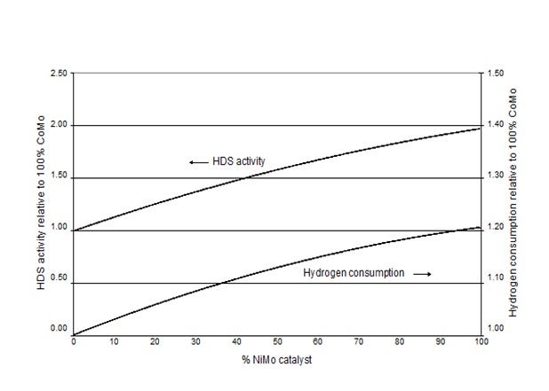
Figure 1: Pilot plant testing of 100% CoMo, 100% NiMo and three combinations of CoMo/NiMo at 640 psi H2.
From the above it is obvious that the required H2/oil ratio is highest when using NiMo and lowest with CoMo.
The EOR temperature is generally lower when a NiMo catalyst is used compared to a CoMo solution. This is because the N cannot be removed due to equilibrium constraints at high temperatures, and with higher contents of organic N in the oil the hydrogenation route cannot be used. Since the NiMo has a low activity for the direct desulphurization route it is not recommended to operate at these conditions. In some Asian countries there are specifications on product color, which also deteriorates with temperature. Some of the units Topsoe have designed for this part of the world are equipped with our color removal technology (polyshift) downstream the HDS section in order to operate the HDS catalyst at a higher EOR temperature.
High H2 pressure: > 950 psi
In high pressure operation a NiMo is in general the preferred choice due to its high hydrogenation activity. Despite the favorable pressure the LHSV is still in the same range, but as the aromatic saturation increases with pressure these units need to have a high H2/oil ratio, sometimes higher than 6,000 SCF/bbl. High pressure units are used when very difficult feedstocks are treated, e.g.,
crudes of South American origin or any feedstock containing more than 50% cracked LCO.
Michael Chuba (Sunoco)
Sunoco has multiple hydrotreating units including one hydrocracker that produce ULSD. These units' range in operating pressures from 475 to 1450 psig with EOR temperatures ranging from 670-770F, depending on pressure, feed, heater RACT limitations, and/or metallurgical temperature limitations.
The majority of our ULSD units use high efficiency CoMo catalyst. Now that we are into our second and third loads, we have begun using a combination of regenerated and fresh catalyst loads. Initially we had limited the use of regenerated catalyst to the top beds or in applications where the service was not as severe. With experience, we have found good activity with the regenerated material and have pushed more and more regenerated material into the mix with as much as 100% regenerated catalyst in some of reloads.
As for how many times ULSD catalyst can be regenerated, this depends on the condition of the catalyst. The main limitation to multiple catalyst regenerations is catalyst L/D. In applications employing vacuum catalyst unloading the abrasive handling of the catalyst can result in particle L/D of less than 2. Below this range we would typically not reuse this material. Other criteria for not reusing catalyst are high metals and other contaminate levels. Overall, multiple regeneration of ULSD catalyst can be done.
Charles Olsen (ART)
The types of catalysts being used in ULSD are typically current generation, high activity Type II catalysts, and the catalyst loadings cover the range from 100% CoMo catalysts for lower pressure units to 100% NiMo catalysts for higher pressure units with no H2 constraints. A large percentage of units have been using a combination of NiMo and CoMo catalysts as in the SmART Catalyst System® from Advanced Refining Technologies. The SmART system is based on a staged catalyst approach utilizing a high activity CoMo catalyst like 420DX for efficient removal of sulfur via the direct abstraction route and a high activity NiMo catalyst like NDXi which effectively removes the multisubstituted dibenzothiophenes via the hydrogenation route.
One of the big advantages of using a staged catalyst approach like this is illustrated in the figure below. The figure shows that as NiMo catalyst is added to the catalyst system there is a large increase in HDS activity relative to all CoMo reference, and eventually, a maximum in HDS activity is reached.
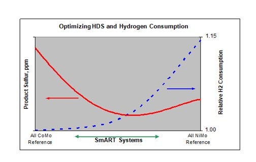
The position and magnitude of this optimum varies with feed and operating conditions, especially H2 partial pressure. The figure also includes the relative H2 consumption, and again, as the percentage of the NiMo component increases, the H2 consumption relative to the base CoMo system increases. Notice, however, that in this case the relationship between H2 consumption and the fraction of NiMo catalyst is nonlinear. In the region where the system shows the highest activity the hydrogen consumption is only slightly greater than that for the all CoMo system, and well below that for the all NiMo catalyst. It is this ability to balance HDS activity and H2 consumption to meet individual refiner requirements that sets SmART apart.
Exact start of run conditions will of course vary with feed and operating conditions, but a typical SOR WABT is around 640-660°F. The typical ULSD unit has a LHSV around 1 hr-1 with an inlet pressure of around 850 Psig, although ULSD unit pressures vary from a low of around 500 Psig to a high around 2000 Psig. Observed deactivation rates have been in the range of 1-3°F/mo depending upon the feed and operating conditions.
End of run conditions have been determined by a unit constraint such as a reactor inlet temperature limitation or some product attribute, most commonly product color. We’ve observed, as an average, an EOR WABT around 730-740°F. It’s important to note that for diesel product color it is the reactor outlet that is important. We’ve observed reactor outlets as high as 760°F in some cases with no detrimental impact on product color.
There are also a number of ULSD units which suffer from Silicon and Arsenic poisoning. These units tend to have shorter run lengths and will include a sizeable bed of guard catalyst to protect the active catalyst below.
Perhaps somewhat surprising is the number of ULSD units which have exceeded expectations in terms of cycle length. Many grassroots and revamped units were designed for 2 year cycles and actually ran 3-4 years. For the units which have changed out we’ve seen catalyst loadings which include adjustments to the relative amounts ofNiMo and CoMo catalysts, the addition of new, higher activity catalysts which weren’t available when the unit started up, and in some cases a portion of catalyst load is made up of reactivated catalysts. These reactivated catalysts are regenerated and further processed to redisperse the active metals using proprietary processes such as PHOENIX™ which was developed by ART and is now currently offered by TRICAT. In most of the latter cases reactivated catalyst makes up only part of the reactor fill with the remaining volume new catalyst.
Dave DiCamillo (Criterion Catalysts & Technologies)
Actually, some ULSD units containing Criterion catalysts are still on their first cycle, some due to use of 2nd generation ULSD catalysts in units designed on 1st generation products or operating with a significantly easier feed than assumed in the design basis. Each ULSD operation is unique, so there is not a single answer to the first part of this question (See also response for Question 22).
· SOR operating conditions are dependent on the unit design and feed quality. We have observed SOR temperatures ranging from 600 to 700°F. Obviously the more robust the unit design, the lower SOR temperature is likely to be.
· EOR operating conditions are dependent on refinery objectives for things like fixed or flexible turnaround/catalyst changeout date. With a flexible EOR date, the refiner can run the normal ULSD feed until the run becomes limited by reaching charge heater or catalyst activity limits. In many units, aromatic saturation thermodynamic equilibrium still limits the ability to make sulfur or color specs at EOR, however the maximum temperatures achievable are higher than originally anticipated, particularly in units processing only straight run feeds. Maximum reactor outlet temperatures remain a strong function of feedstock type, operating pressure (H2 partial pressure), catalyst type and LHSV.
There is also no single answer to the second part of this question - catalyst selection. Catalyst selection can depend on many factors such as:
· Unit design
· Feed quality
· Product quality requirements
· Hydrogen consumption and availability
· Cycle length targets
· Cost
· Refinery philosophy on catalyst type, e.g., fresh only, internal reuse, resale catalyst, etc.
Discussion of next cycle expectations with your catalyst supplier will help to formulate objectives, especially if they differ from the current operation. The best approach is to be clear on processing objectives (minimum requirements and desired targets) and prioritize them in the catalyst RFQ (request for quotation) so that vendors can provide some options to consider. A catalyst supplier will typically have a portfolio of products that can be customized for different operating modes such as maximum cycle length, maximum feed rate, minimum hydrogen consumption, etc.
Year
2010
Process