Novel Encounter Training for Console Operators
Session Start End
-
Peter Blaser (CPFD Software, LLC)
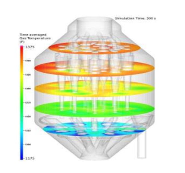
CFD has been successfully used to predict afterburn in FCC regenerators. A published example was presented as part of the CFD Case Studies workshop at the 2012 AFPM Cat Cracker Seminar (session CAT-12-101) as well as at the 2012 AIChE annual meeting. For more information see: 'Clark, S., Snider, D., and Fletcher, R, "Multiphase Simulation of a Commercial Fluidized Catalytic Cracking Regenerator",Presented at the AIChE 2012 Annual Meeting, Pittsburgh, Pennsylvania, (2012)'.
In that example, the CFD model accurately predicted the magnitude of the afterburn (approximately 100 degrees F as shown in the attached image) as well as the non-uniformity of cyclone temperature distribution. Once validated, the model was used to rule out the distribution of spent catalyst as the primary cause of the afterburn for that case. Instead, the afterburn was attributed to poor mixing of the multiple air sources with the catalyst in the shallow bed, leading to some undesirable dilute phase combustion. An animation of the results can be found at http://cpfd-software.com/resources/videos/cfd-simulation-of-a-full-scale-commercial-fcc-regenerator.
However, other unpublished CFD studies have reached different conclusions for other FCC regenerators. Recent analysis of a regenerator at a US refiner showed asymmetric afterburn was directly related to the mixing of the spent catalyst in the bed as directly influenced by the spent catalyst distributor. Based on this, it's not likely that a single hardware change will be effective in all cases. Instead, CFD can be used as a tool to understand the root cause of the phenomena resulting in the afterburn for a particular regenerator operating under a particular set of process conditions. Using the CFD models, proposed modifications can be evaluated and compared prior to shut down and installation.
Kenneth Bryden (Grace Catalysts Technologies)
Fundamentals:
A number of factors influence butylene selectivity in the FCC LPG stream. Figure 1 summarizes the fundamentals of butylene selectivity and maximization. The cracking pathways involved can be thought of as four stages. In Figure 1, the desired pathways for maximizing butylenes are in green and the undesired pathways are in red. The first stage is cracking of the feed to naphtha range olefins. These cracking reactions can occur on zeolite or matrix. In the second stage, these naphtha olefins can react to naphtha paraffins by hydrogen transfer (an undesired pathway), or crack to C3 and C4 olefins. The cracking of gasoline range olefins to C3 and C4 olefins is much faster on ZSM-5 zeolite than Y-zeolite. Catalyst factors that influence the selectivity of butylene versus propylene will be discussed later in this answer. The C3 and C4 olefins that are produced in stage 3 can further react by hydrogen transfer to form propane, iso-butane and butane, which are undesired when maximizing butylene. These reactions occur much faster on zeolite than on matrix. Based on this fundamental reaction scheme, butylenes can be maximized by decreasing the hydrogen transfer activity and by minimizing the cracking of naphtha olefins to propylene. The effects of individual factors on butylene selectivity are discussed in detail below.

Feedstock Effects:
The chemical nature of the starting feedstock will affect the products that can be produced from it. As a feed becomes more paraffinic, butylene production increases. As a feed becomes more aromatic, the olefinicity of the LPG stream will drop.1 As a feedstock becomes more naphthenic, LPG olefinproduction drops. This is because naphthenes are good hydrogen donors and react with gasoline range olefins to make aromatics and gasoline range paraffins.2 Since gasoline range olefins are the precursors to LPG olefins, this depletes the pool of available material to make LPG olefins and reduces LPG olefinicity.
Operating Condition Effects:
Typically, total C4 production depends on conversion, regardless of if the conversion is achieved by reactor temperature or catalyst-to-oil ratio.3 However, the ratio of isobutane to butylene is strongly influenced by reactor temperature. Since hydrogen transfer has higher activation energy than cracking, the rate of cracking increases faster with temperature than the rate of hydrogen transfer4. Thus, as reactor temperature increases, the ratio of iC4/C4= is lowered. As a rule of thumb, the ratio of iC4/C4= drops by 0.025 per 10°F increase in reactor temperature.
Changing reactor pressure will also affect the olefinicity of the C4 stream. Since hydrogen transfer is a bi-molecular reaction, decreasing reactor pressure lowers hydrogen transfer and increases the olefinicity of the LPG stream. Data quantifying the effect of reactor pressure on butylene selectivity can be found in Reference 5.
Increased carbon on regenerated catalyst (CRC) reduces the rate of hydrogen transfer reactions and results in a more olefnic LPG stream. Also, increased CRC will usually lower overall conversion.
Catalyst Effects
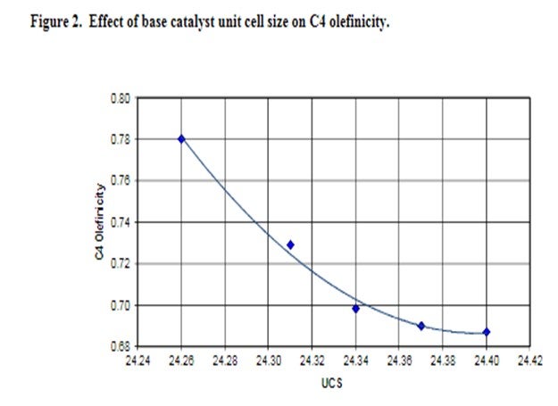
Base catalyst affects butylene selectivity through both the rate of hydrogen transfer and through the amount of naphtha range olefins produced. Since increased hydrogen transfer reduces LPG olefinicity, butylene olefinicity drops as the amount of rare earth on zeolite increases, as measured by unit cell size (UCS). Figure 2 presents C4 olefinicity as a function of base catalyst unit cell size. Higher matrix activity increases C4 olefinicity. Lowering the zeolite/matrix ratio of the base catalyst increases gasoline range olefins and thus the amount of butylene produced from these precursors.
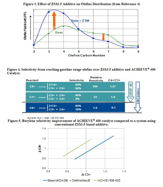
ZSM-5 based additives have a significant effect on the olefinicity of the LPG stream. ZSM-5 cracks the C6+ gasoline range olefins to propylene and butylene. Figure 3 shows the effect of ZSM-5 on the olefins distribution. Adding more ZSM-5 additive will deplete the gasoline range olefins and produce both more propylene and butylene. The increased propylene yield with ZSM-5 additives is not always desirable. A better solution is to boost zeolite isomerization activity within the catalyst to selectively increase the yield of FCC butylene. Grace’s ACHIEVE® 400 catalyst is formulated with multiple zeolites with tailored acidity, to deliver an optimum level of butylenes to keep the alkylation unit full and maintain refinery pool octane. With traditional ZSM-5 technology, cracking of gasoline olefins continues past C7 into the C6 and generates a disproportionate amount of propylene relative to butylenes as shown in Figure 4. The newly developed dual-zeolite technology in ACHIEVE® 400 works synergistically with Grace’s high diffusivity matrix, to selectively enhance olefinicity, preferentially cracking gasoline olefins at C7 and above into butylene. The result is a higher ratio of C4 to C3 olefin yield than separate light olefins additives. Figure 5 illustrates the butylene selectivity improvement of ACHIEVE® 400 catalyst compared to a system using conventional ZSM-5 based additive6. In addition to increasing butylene selectivity, ACHIEVE® 400 has been shown to increase the octane of FCC naphtha.
In summary, butylene selectivity is influenced by a number of complex factors in the FCC. Proper choice of catalysts and additives based on operating objectives and unit constraints is critical in maximizing butylene selectivity. Grace’s technical service team has the experience and resources to help refiners evaluate feed, operating condition and catalyst shifts to maximize butylene selectivity.
Kenneth Bryden (Grace Catalysts Technologies)
While you would expect oxygen to mostly react with hydrogen to form water in a riser, some oxygenates do form.
Phenols and other oxygenates can form in the riser via two mechanisms-
•Cracking of molecules in the feed that naturally contain oxygen bonded to the aromatic structures (for example: phenols, benzofuranes and quinolones)
•Reaction of extraneous molecular oxygen with hydrocarbons in the riser.
Sources of extraneous molecular oxygen in the riser include:
•oxygen carryover that is entrained in the catalyst from the regenerator
•oxygen from using air as the aeration media for the regenerator standpipe
•air entrained or dissolved in the feedstock
Since increasing reactor severity will result in an increase in catalyst circulation, it is likely that the increased oxygenate production being observed is from the higher catalyst circulation which is increasing the entrained molecular oxygen carryover to the riser.
The responses to question 106 at the 2006 NPRA Q&A and Technology Forum and question 91 from 2013 AFPM Q&A and Technology Forum contain additional information on this topic.
David Strangmeier (NALCO Champion)
Monitoring parameters of the FCC such as density and height of catalyst beds, gas and/or solid distribution of the cyclones, air distributor, slide valves and standpipes are accomplished through measurements of pressure, pressure drop and temperature at various locations. These measurements are indirect. Gamma scans (density measurements) and tracer studies (flow and distribution of gas and/or solids) will provide real time direct measurement for improved diagnosis and troubleshooting around the riser, reactor, stripper, regenerator, and standpipes. A well-planned benchmark test can help to document the before and after effects of design or operational changes.
Specific examples include:
• Identify mal distribution of catalyst at the air grid
• Gamma scan to evaluate dip legs, flapper valves, and bed levels
• Main Fractionator Gamma Scans to identify damage, fouling, flooding, entrainment, or weeping
• Radioactive gas tracing of the stripper for hydrocarbon carries under detection
Minh Dimas (CITGO)
One of our refineries has developed limits for pressure drop through the reactor circuit. The maximum allowable pressure drop is determined by the difference between the upstream reactor or heat exchanger design pressure and the set pressure of the relief valve on the high-pressure separator. The purpose of the alarm is to ensure that the upstream vessel’s design pressure will not be exceeded before the pressure at the downstream relief valve reaches the set pressure.
Tim Lewer (Shell)
Pressure drop limitations across the high-pressure section of a hydrotreating unit are common in refineries. They can be set for many reasons, including but not limited to
1. Equipment design – High pressure separators are controlled to provide the proper suction pressure to the recycle compressor. If the reactor and exchanger train build high pressure drop, the maximum allowable pressure in those vessels may be exceeded in order to maintain the proper high pressure separator pressure. A pressure drop alarm may be set to avoid exceeding the upstream equipment design pressures.
2. Reactor catalyst monitoring – High differential pressure alarms are common for entire reactor trains if individual catalyst bed pressure drop indication is not available. This is important for catalyst health monitoring, especially if guard beds are not present. In addition, reactor internals may have specific differential pressure limitations.
Exchanger fouling detection – It is not typical to have a lot of pressure or temperature indication on the feed/effluent exchanger train so it can be difficult to detect exchanger fouling.
Martin Gonzalez (BP)
The buildup of system pressure would push a centrifugal recycle compressor back on its curve, so setting a pressure drop limit across the entire reactor circuit would help prevent compressor surge.