
Dan Sack
Becht

James R. Esteban
Global Director, Technical Sales, Catalyst and Reactor Engineering
Unicat Catalyst Technologies


Question 24: Given the potential consequences of back flow in high pressure hydroprocessing services, such as furnace tube rupture and pump shutdown, what layers of protection are being employed to reduce risk?
ESTEBAN (Suncor Energy, Inc.)
We are going to skip the first slide.
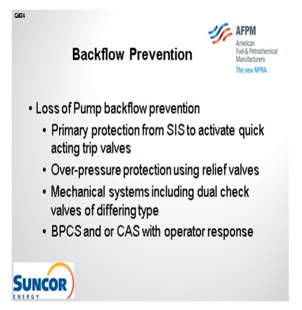
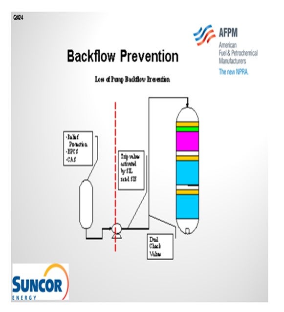
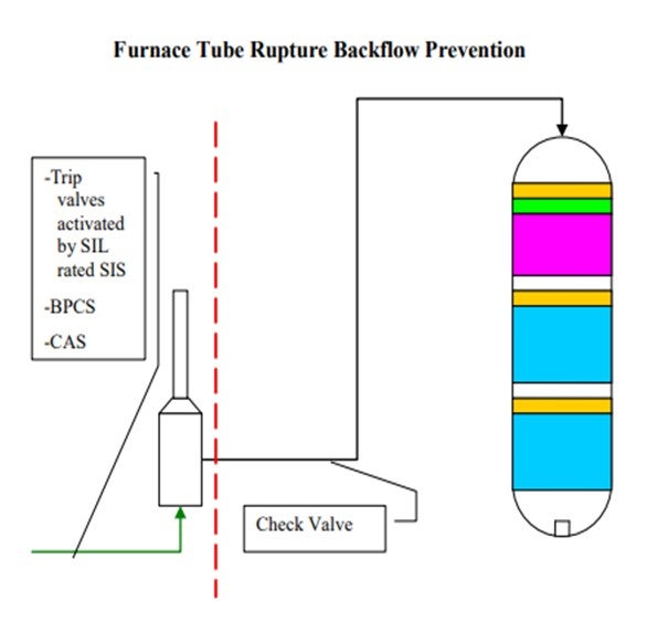
The second slide shows a simple depiction of the layers of protection that we use at our different sites. In some cases, we have relief protection, basic process controls, and critical alarm systems on our feed drums to prevent a backflow scenario or the consequences of a backflow scenario. That being said, though, relief valves do not always provide an adequate level of protection for high pressure units. So obviously, take that with a grain of salt. Our primary layer of protection is provided by our trip valves which are activated by SIL-rated instruments. We do not have an SIL rating in all cases; but in some cases, it is required to get the level of protection we need. And then, of course, we also employ dual check valves of differing types downstream of our pumps. Those check valves will typically wind up on our critical check valve system as well.
The scenario is similar where you have backflow. It is not so much the concern of backflow of reactor contents through the furnace, but more just a loss of containment in the furnace itself. We do not treat these furnaces in our hydroprocessing units any differently than we do any of our other furnaces in the refinery. They all have an integrity operating window that we would like to stay in. That window defines at what burner pressures we need to operate and, of course, at what skin and overall box temperatures we can operate.
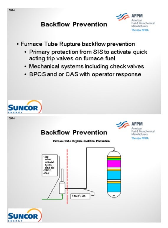
Our layers of protection are very similar here in that we have trip valves activated by SIL-rated instruments and which are only SIL-rated as required. And of course, we have basic process controls and critical alarm systems. In some, but not all, cases, we do have check valves downstream of our furnaces. That is not a standard at all our sites. However, on some sites, we are consistent about having check valves downstream of our furnaces.
KEVIN PROOPS (Solomon Associates)
I would like to comment on the heater part of the question. Reactor charge furnaces potentially have substantially higher consequences of failure than do most of the other furnaces in your refinery, so you need to be a lot more scared of them than you do of the other ones.
First, this is generally an exothermic process; so, the best case is probably that the furnace is not firing or is only minimally firing. Adequate feed-effluent heat exchange reduces firing and thus the risk of failure from flame impingement. Second is the inherent safety design. If you can go to a single-phase furnace instead of a two-phase furnace, then if it does rupture, your consequence will probably be a lot less. That also gets into the control system issues. Some refiners use hot oil utility instead of a fired heater in the hydrotreater. This is inherently safer.
Then you get into how to avoid a tube failure in the first place. There are a lot of ways to do that, but consider dry point in naphtha units, burner ring pressure controls and interlocks, and maintaining the cleanliness of the burners (fuel gas filtering). Adequate burner-to-tube spacing, feed filtration, tube monitoring (thermography), operator rounds frequency, and upgraded tube metallurgy can all add layers of protection.
Finally, it comes down to culture as well. You do not want to get into a situation of risk of a failure competing with profit to keep the unit maximizing at full throughput. Unfortunately, I have seen a case where that did happen: A furnace was experiencing flame impingement, and the operators did not reduce charge to the unit. After one shift, a tube failed, which led to the entire unit being consumed in a flash fire within a few seconds. We were very fortunate that there was no one outside at the time it happened; if there had been, we would have killed anyone in the unit.
ESTEBAN (Suncor Energy, Inc.)
We do treat them differently depending on their operating pressures and/or requirements. Certainly, from a design standpoint, the operating envelope for each individual piece of equipment changes how the furnace is designed overall. That being said, we evaluate all equipment using the same standard with a process hazard analysis to determine the appropriate layers of protection. Given the required layers of protection, we identify additional safeguards as required by LOPA. SIL-rated instruments, for example, are not required for all burner management systems. However, in some cases, they may be required because the consequences of failure are higher.
So yes, the consequences are significantly greater on a high-pressure furnace. The assessed risk ranking would define how those layers of protection will appear. In some cases, you will see a simpler system on a furnace; and in others, much more complex layers of protection will be applied because of the potential consequences of equipment failure for that furnace. So, to re-phrase my response, I will say that we evaluate every piece of equipment using the same processes.
ESTEBAN (Suncor Energy, Inc.)
In order to reduce the risk of potentially catastrophic consequences related to backflow in high pressure hydroprocessing services Suncor Energy, Inc. uses several independent layers of protection at operating pressure boundaries. One common boundary is for hydroprocessing units, is between the unit feed drum and the reactor charge pump. A typical hydroprocessing unit will have relatively low design pressure equipment upstream of the reactor charge pump which boosts the operating pressure of the feed stream to the much higher reactor operating pressure. As such preventing back flow in the event of the loss of a feed charge pump is critical to prevent equipment failure in upstream equipment with catastrophic consequences. In this application Suncor Energy, Inc. applies the use the following layers of protection:
1. Primary protection is typically a Safety Instrumented System (SIS) that monitors the run status of the feed charge pump via multiple direct and indirect instrumented signals and activates quick acting trip valves and in some cases closes the feed charge control valves in the event of a shutdown. In some cases, depending on the unit specific hazard analysis these systems may be SIL-rated to ensure reliable operation when activated. In addition, these systems are often designed to be activated by any one of several different instruments used to sense a potential backflow scenario, i.e., low-low flow shutdowns and low-low feed controller differential pressure shutdowns.
2. In some cases, pressure relief valves are used as layers of protection for overpressure due to backflow, but caution must be applied when relying on a relief valve as protection for vessels, such as feed drums, since these valves are not always sized for backflow scenarios.
3. Mechanical safety systems are also employed depending on unit design. While these systems are often not credited in a process hazard analysis of a unit they can provide additional layers of protection. Typical installations include dual check valves of different design which are often deemed critical check valves that require routine maintenance.
4. Provided the design of the system and equipment in some cases basic process controls and/or critical alarms with operator response are employed as additional layers of protection.

In addition to backflow prevention and protection as it relates to pressure boundaries, furnace tube ruptures can result in backflow from multiple large high-pressure vessels to atmosphere with catastrophic consequences. In order to address the release of reactor and high-pressure circuit equipment, layers of protection must be applied to the feed furnaces that prevent operating windows that have the potential to create damage resulting in tube rupture. The layers of protection employed for this scenario do not differ from those on other furnaces in Suncor’s refineries, as all furnaces are evaluated for tube rupture scenarios. However, in this application Suncor Energy, Inc. applies the use of the following layers of protection:
1. Primary protection is typically a SIS that monitors furnace flows, temperatures, and fuel and box pressures via multiple direct and indirect instrumented signals and activates quick acting trip valves on fuel supply and in some cases closes the fuel supply control valves in the event of operation outside a preset operating window. These SISs often activate related SISs to stop process flows. In some cases, depending on the unit specific hazard analysis these systems may be SIL-rated to ensure reliable operation when activated. In addition, these systems are often designed to be activated by any one of several different instruments used to sense operation outside of the specified window, i.e., low-low flow shutdowns and high-high burner pressure shutdowns.
2. Mechanical safety systems are also employed depending on unit design. While these systems are often not credited in a process hazard analysis of a unit, they can provide additional layers of protection. Typical installations include check valves downstream of furnaces to prevent the backflow of reactor contents. In general, these check valves are not relied upon as fail-safe devices and are not considered critical check valves.
3. Provided the design of the system and equipment in some cases basic process controls and/or critical alarms with operator response are employed as additional layers of protection.
Year
2012
Process
Question 25: What is your philosophy for mitigating fouling and corrosion in reactor effluent cooler systems in hydrotreater or hydrocracker units during a short-term washwater pump failure scenario? How much time is allowed before initiating a unit shutdown?
ROBERTSON (AFPM)
We are going to finish with Question 25. Twenty-six was an Answer Book-only question anyway, and Robert and James have provided answers to 27 and 28 respectively in the Answer Book.
LEICHTY (Chevron USA, Inc.)
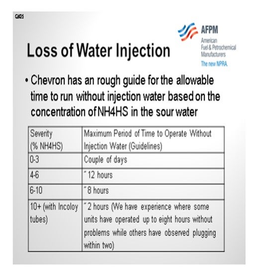
Chevron developed a rough set of internal guidelines that determine the allowable time to run without water injection. The guidelines are based upon ammonium bisulfide (NH4HS) concentration. For units that run at what we call low severity, which is zero to 3% NH4HS, we will allow a couple of days of operation without water injection. As the normal NH4HS concentration of the operating unit sour water increases, we allow progressively less time to run without water injection.
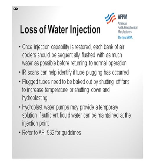
Once injection capability is restored, each bank of air cooler should be sequentially flushed with as much water as possible with all other banks receiving minimum water at all times. We use infrared scans to determine whether or not we still have tube plugging. You can shoot the fin fan banks from up above or from down below, depending on the configuration.
The NH4HS salts in plugged tubes can sometimes be re-sublimed by sequentially shutting off air cooler fans. The increase in bundle temperature can sometimes be enough to allow the ammonium bisulfide salts to vaporize. We have also used temporary solutions, such as hydroblast water pumps, as a mechanism to get water into the unit, but only if 25% liquid water can be maintained. Having less than 25% liquid water can be more damaging than having no water at all because of the potential for rapid hydrochloric acid corrosion.
PUI-NANG LIN (Flint Hills Resources, LP)
Is the table that you presented for the duration of the water outage based on corrosion rate or plugging of a certain percent of the tubes by salt? Does metallurgy of the tubes affect the result?
LEICHTY (Chevron USA, Inc.)
The duration of the water outage is based on plugging and the potential for subsequent corrosion.
STEPHEN PERRY (Motiva Enterprises)
I would propose to you that the Shell’s criteria are slightly different. I also encourage you to do a salt balance because when doing a salt balance, in less than eight hours, you can find out that you could start plugging off tubes that are not going to recover without your ability to get water in there. Companies will have different policies. Also, units salt up at different rates. So, I would definitely do a salt balance, understand your situation, and then make a decision based on all of the information.
LEICHTY (Chevron USA, Inc.)
That is how these tables were developed.
KEVIN PROOPS (Solomon Associates)
I have a follow-up question for Steve Leichty, and maybe for Steve Perry. Do you consider reducing feed rate or cutting out specific feeds when you lose washwater to reduce salt formation?
LEICHTY (Chevron USA, Inc.)
Absolutely. The first action is to shed higher nitrogen crudes and reduce the unit feed rate.
KEVIN PROOPS (Solomon Associates)
I would agree with also pulling the high nitrogen feedstocks out of the unit as a first step.
Year
2012
Process
Question 26: What catalyst and metallurgy design considerations are important when evaluating the co-processing of highly acidic renewable distillates? What can be done to mitigate carbon monoxide formation?
STEFANO MELIS (Albemarle Corporation)
Acidity of renewable distillates can be intrinsic of the material (free acids of the vegetable oil) or generated during its conversion in the hydrotreating unit. Typically, free acids in vegetable oil amount to about 5%. This means that crude vegetable oil has a TAN number around 7, which requires special metallurgy for the pipelines to the feed drum. Once the vegetable oil (VO) is mixed with oil, acidity is reduced by dilution. For a typical co-processing operation, where VO intake ranges around 5% to 10%, standard metallurgy is, therefore, suitable for the connection between feed drum and reactor. At increasing intakes (i.e., above 10%), special metallurgy would be required.
An alternative is to directly resort to refined vegetable oil. In this case, VO is acid-free; therefore, no corrosion issues are expected in any part of the feed section. This solution also prevents fouling problems associated to VO impurities, such as sterols and phospholipids.
Acids are also formed during the conversion of VO to hydrocarbons. Indeed, triglycerides decompose to carboxylic acids (which then further react to yield paraffins). Since the triglycerides decomposition proceeds gradually along the reactor and the produced acids are readily converted, no local spots with acidic material are expected. Standard metallurgy of hydrotreating units is, therefore, suitable for these operations, except for those units with very poor metallurgy (often with very low design pressure).
As mentioned above, decomposition of triglycerides leads to carboxylic acid formation which, in turn, yields paraffins. This latter step can occur through different mechanisms: hydrodeoxygenation (HDO, yielding paraffins and water), decarboxylation (DCX, yielding paraffins and CO2) and decarbonylation (DCN, yielding paraffins, CO and water). The latter two mechanisms are linked by the Water Gas Shift reaction. The straightforward way to decrease CO is to force the reaction to proceed through HDO, favored by high pressure and low temperature. Catalyst selection is important since the system requires high activity both for HDS (in order to reduce the operating temperature to reach the S target) and for hydrogenation (to enhance HDO). Another possibility is to catalyze the hydrogenation of CO to methane. This reaction, however, being highly exothermic, can cause local high ΔT, resulting in possible formation of hot spots. Additionally, the methanation reaction has high hydrogen consumption and, as such, is an inefficient way to use hydrogen. This should also be taken into account is considering downstream methanation, for example, in the high-pressure separator.
In general, CO generation from bio-feed co-processing can be managed. Driving the reaction of renewable material through DCN leads to a significant reduction in H2 consumption compared to alternatives. Produced CO accumulates in the recycle gas and leads to strong inhibition of HDS reactions, but this effect can be kept under control with proper catalyst selection. Depending on the configuration of the refinery hydrogen network, CO containing gas can be either purified (for example, by PSA) or directed to other units where its inhibition effect is less severe.
Overall, operating strategy and catalyst selection for the co-processing of renewable material should be analyzed in great detail to find the optimal reaction path that provides the best compromise between H2 consumption, detrimental effects of CO and product yield structure.
Year
2012
Process