
Cybersecurity Session: Regulations, Policies, and What is on the Horizon
Cybersecurity threats continue to the ONG and petchem industry and the government has countered these threats with new regulations, policies, and voluntary programs. Hear the latest on this new evolving regulatory landscape
Session Start End
-
FSO Best Practices: From Inspectors to Protestors
FSOs are the front line of security and now have to deal with demonstrations, drones, and new cyber inspectors--are you prepared when they arrive at your gate?
Session Start End
-
Selling Security to Upper Management
Obtaining capital within any organization presents challenges to security practitioners, as it often difficult to compete with direct operational investments. However, in this session Dr. Wilkins will provide practical strategies to increase the likelihood of funding – allowing you to convert your ideas into funded projects. This process requires an understanding beyond the boundaries of risk mitigation and traditional project management, focusing instead on core business acumen and political awareness. With over two decades of experience in the industry, Dr. Wilkins systematic approach to project budgeting, planning, and execution will provide you the tools and credibility to sell to the C-Suite.
Session Start End
-
Cyber-Physical Security Teams Working Together
Join us for a session discussing the important need for increased collaboration between the security team members to deal with new cyber threats and current and future regulatory requirements, and soooo many new voluntary initiatives.
Session Start End
-
TSA Pipeline Security Directives Implementation
Implementation of the TSA Security Directives are in full swing---hear the latest on any implementation and compliance issues and the next steps for pipeline security.
Speakers
Session Start End
-
DHS-CFATS Changes, Cyber, and Global Chemical Security
DHS’s Cybersecurity and Infrastructure Security Agency works closely with industry to help build a sector that can defend against both cyber and physical threats. During this session, CISA will speak to the future direction of the Chemical Facility Anti-Terrorism Standards (CFATS) regulations, CFATS reauthorization priorities, and insights from the first year of CFATS inspection audits. This session will also provide brief conference attendees on the current and future work of the Global Chemical Security Congress.
Session Start End
-
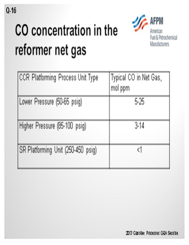
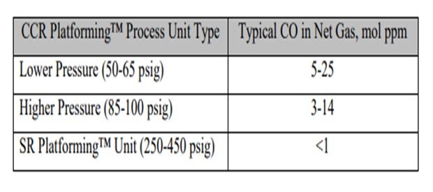
Question 16: What is the typical carbon monoxide (CO) concentration in the reformer net gas? How is the CO content measured? What are the potential effects to downstream units from the CO?
MELDRUM (Phillips 66)
Carbon monoxide can form in reformer units as the hydrocarbon reacts with moisture under very low-unit pressure conditions. Typically, semi-regeneration reformer net gas would have nil CO and only a minimal amount in a CCR-type unit. I expect it to probably be on the order of 5 ppm (parts per million), though some units report routine measurements of 10 to 20 ppm CO in their net hydrogen off gas.
One of our cyclic units that was operating at 400-pound had CO as high as 20 ppm in its net hydrogen stream when the recycled moisture rose to around 300 ppm. The excessive water entered the reformer from a leaking side reboiler on a wet debutanizer that used a slipstream of the reformer reactor effluent as the heat source. The water then returned to the reformer product separator. The high CO caused deactivation in the catalyst in a downstream isomerization unit.
Accurate measurements of CO in the net gas are difficult. Reformer units are not expected to have much CO, so they seldom have an online analyzer. A colorimetric tube – Gastec or Dräger type – can be used to give an indication of the presence of CO, but accuracy for a quantified number is difficult and requires the use of a carbon pre-tube to remove the hydrocarbons.
CO is detrimental to downstream hydrogen-using units in three principal areas. CO in hydrogen being fed to a distillate hydrotreater will methanate, consuming the hydrogen that would have otherwise been used for the desulfurization reactions. This will have the effect of lower catalyst activity. CO in hydrogen fed as a makeup stream to an isomerization unit will also methanate and form moisture that will deactivate the isomerization catalyst. CO that did not methanate in the second example could act as a poison to the platinum metal function of the isomerization catalyst. UOP suggests a CO limit of 1 ppm max for isomerization hydrogen makeup gas. My Answer Book response also includes some of the common steps used to minimize CO formation in reformer units, particularly in a CCR unit.
BULLEN (UOP LLC, A Honeywell Company)
As you can see in this table, we have correlated some different types of operation and ranges of CO levels. As Craig alluded, the numbers vary quite a bit, which can be due to conditions in the unit, as well as analytical capabilities. There seems to be a trend that the lower pressure units generate more CO than higher pressure units.
The laboratory method we recommend using is UOP 603, which is a laboratory method for CO and CO2 and hydrogen. However, a lot of refiners cannot do this method. The gas detection tube route is fairly common. Our point of view is that with the gas detection tubes, if one carbon pre-tube is good, then two is better. So, we usually ask them to use two tubes instead of one to help eliminate the breakthrough of hydrocarbons that can make a false high value for CO.
As Craig said, the issue with chloride and alumina isomerization catalyst is that you will deactivate the catalyst. However, if you are using another type of catalyst, like the Par-Isom catalyst or zeolitic catalyst, the actual suppression you will get will be very dependent on what temperatures you are running. As you approach the 400°F temperature, you tend to methanize the CO in the first part of the bed. So CO tends to have less of an effect on the metal function of the isomerization catalyst and becomes more of an issue of activity suppression due to the water on the acid sites. The same would apply if you had a saturation unit with platinum catalyst. It would also behave in a similar manner to these higher temperature isomerization units.
R.K. (RICK) GRUBB (Chevron Products Company)
Another aspect needs to be mentioned for the lower pressure reforming units. You have to take into consideration your nickel carbonyl formation when you shut down a hydroprocessing unit that is using the reformer hydrogen. You may have to either swap the hydrogen source or think of another shutdown procedure that will ensure no nickel carbonyl formation.
CRAIG MELDRUM (Phillips 66)
CO is detrimental to downstream hydrogen using units for three principal reasons:
1) CO will methanate in HDS (hydrodesulfurization) units consuming hydrogen, which will take away catalyst activity.
2) Much of the CO will methanate in isomerization units, forming water that will deactivate the isomerization unit catalyst.
3) The non-methanated CO in the isomerization unit will poison the metal function of platinum on the catalyst.
Note: The UOP suggested CO limit on isomerization unit hydrogen makeup gas is 1 ppm (10 ppm for CO + CO2). UOP reports that CO levels greater than 6 ppm will not allow the isomerization unit catalyst to meet its cycle life guarantee.
The common steps to minimize CO formation in the reformer are:
• Minimize moisture in the system (feed water control and good regeneration drying),
• Minimize the last reactor temperature,
• Maximize the H2/HC ratio, and
• Minimize catalyst circulation rate in a CCR.
PATRICK BULLEN (UOP LLC, A Honeywell Company)
The CO concentration in reforming unit net gas can be impacted by a number of factors: system pressure, temperature, and moisture in the recycle gas, as well as the H2/HC (hydrogen/hydrocarbon) of the operation. Operating pressure has the most significant impact on CO production in a reforming unit. CO formation in reforming operation is produced via steam reforming of hydrocarbons:
H2O + CH4 ↔ CO +3H2
Thermodynamically, this CO formation reaction is more favorable at lower pressures. CO production is inversely proportional to the pressure squared. As such, a semi-regeneration reforming unit, being significantly higher pressure than typical continuous reforming units, will tend to produce less CO than a typical continuous reforming operation. Likewise, the lower pressure high severity reforming unit operation is more favorable for CO productions.
Commercial reforming net gas CO data from CCR Platforming™ process units can range from 1 to 40 mol ppm. The table below indicates typical ranges for various unit types. Typically, CO levels in the semi-regeneration reforming units are at trace ppm levels due to the high pressure and low-moisture range operation.
For testing of CO in reformer net gas, UOP recommends method UOP 603 for trace CO and CO2 in hydrogen. For CO in light gaseous hydrocarbons, analysis by GC is recommended. Analysis by gas detector tubes can also be considered for measuring CO at elevated levels when used with several carbon adsorbing pre-tubes.
CO in reforming net gas can have an impact on downstream users that may be sensitive to CO or H2O that may be formed due to the reverse steam reforming reaction, also known as the methanation reaction. In the case of a Butamer™ and Penex™ catalyst, water is a permanent deactivator. A typical rule of thumb is that 1 pound of H2O kills 62 pounds of Butamer™ and Penex™ catalyst.
For other types of catalysts, such as Par-isom™ Process and zeolitic isomerization catalysts that operate at higher temperature, the water generated from methanation of CO is a temporary activity suppressant. Platinum-based BenSat™ catalyst behaves similarly to these isomerization catalysts.
GARY HAWKINS (Emerson Process Management)
With respect to the second part of the question, the carbon monoxide content, as well as other components in the net gas of a naphtha reforming unit, can be measured with a variety of measurement principles depending upon the accuracy and reliability required, other species present that may interfere with a particular technology, and the expected range of concentration of carbon monoxide. These same comments apply to measuring other refinery gases, such as the net hydrogen and PSA (pressure swing adsorption) tail gas from steam reforming units for hydrogen production.
Year
2013
Process
Question 17: How many continuous reforming operators have completed a catalyst change while the unit continues to operate? What variables should be taken into account when planning such a change?
ADAMS (HollyFrontier Corporation)
HollyFrontier has two CCRs: one at Tulsa that was converted from a semi-regeneration reformer and one at Artesia. We have not done a catalyst change at the Tulsa refinery CCR, but we have done an online catalyst change at Artesia. Essentially, we just made up more catalyst and purged the catalyst out of the regeneration section. It took about four or five days to completely purge the old catalyst out and replace it with a new catalyst. The downside was that we spent more on catalyst; because as the new catalyst moved through the system, we ended up using 10 to 15% more in order to complete the purge.
BULLEN (UOP LLC, A Honeywell Company)
Based on our experience, we estimate that about 10% of the reloads have been on-the-fly-types of change-out, which equates to about three units a year. We have a procedure for how to do this. As Mark said, one typically has to use more catalyst than if doing a shutdown and change-out just to make sure all of the old catalyst is purged.
Some other issues involve catalyst handling. It can be difficult to get personnel to make sure they segregate the old catalyst from the new, resulting in accidentally putting the old catalyst back into the unit. So, a rigorous process is needed for that.
The circulation rate for the catalyst can be limited by the mechanical moving of the drums and the addition of the drums to the unit, so it may end up being necessary to change the operating conditions to accommodate the more-active catalyst to minimize the extra coke. As the new catalyst comes into the system, it generates a different quantity of coke than the old catalyst; so the operators must be aware that they have to go and adjust the regenerator conditions. One of the drawbacks of doing an “on the fly” type of change-out is that one cannot inspect the system; in particular, the reactors. If there are any issues related to the reactors, such as high ∆P (differential pressure; DP) or poor distribution of the reactor temperatures, those problem will still exist after changing the catalyst.
Finally, the density of the two catalysts – the old versus the new – can impact the circulation system: so be aware of those differences. Also, while oxidized catalyst can be used, this generally puts more stress on the regeneration system to dry out the extra water from the oxidized catalyst. Oxidized catalyst tends to have more water on it.
Finally, you tend to generate more fines when doing a “change-out on the fly”, so keep close attention on the dust collection system.
MELDRUM (Phillips 66)
One of our Cyclemax™ CCR units changed catalyst “on the fly” with such success that the next catalyst changes on another of our Cyclemax™ units will plan to use the “on the fly” method. Benefits include decoupling the catalyst change from a unit outage. The catalyst change mentioned used 106% catalyst to complete the changeover. I want to emphasize that you lose an opportunity to do some vessel inspections with the “on the fly” change. I also emphasize that dust formation is to be watched. In our experience, the reduction zone filter DP increased significantly, resulting in much more frequent changes of that filter. In my Answer Book response, I have provided some parameters used for the example I have referenced.
MARK ADAMS (HollyFrontier Corporation)
HollyFrontier has two CCRs in its system: Artesia and Tulsa. In Artesia, the CCR catalyst was changed while the unit continued to operate. The upside is that the unit continues to run. The downside is that 10 to 15% more catalyst is used as some fresh catalyst is purged along with the old catalyst due to mixing. At Tulsa, the catalyst in the CCR has not been changed since the unit started operation.
PATRICK BULLEN (UOP LLC, A Honeywell Company)
The basic principle of the “Change-out on the fly” procedure is that while the reforming unit continues more or less normal operation, used catalyst is continuously withdrawn from the unit and replaced with fresh catalyst. The used catalyst is removed from below the regeneration tower, allowing the coke to be combusted before unloading. The fresh catalyst is added into the catalyst circuit just below the withdrawal point using the normal catalyst addition system.
In recent years, UOP estimates that about 10% of all continuous reforming unit reloads have been done while the reactors continue to process feed and produce valuable products. The procedure can be implemented on all types of UOP CCR Platforming™ Process units (atmospheric, pressurized, and Cyclemax™ regeneration sections) and also many of the units designed by others. Using this procedure allows operators to capture the benefits of improvements in catalyst technology or to replace catalyst that is underperforming as a result of poisoning or operational problems without a complete shutdown of the reforming unit.
While the “Change-out on the fly” procedure is a simpler compared to a full unit shutdown, there are a number of issues that need to be considered in the planning stages.
• Catalyst handling, either of the fresh or used catalyst, is frequently the rate limiting step in the change-out procedure. The team responsible for catalyst handling will need to carefully plan how to safely and efficiently move and keep separate the drums of old catalyst and the new catalyst.
• While continuing to process feed and producing reformate and hydrogen, it may not be possible for the reactors to operate at design conditions. It is necessary to keep the coke level on the catalyst in a range that the regenerator can sufficiently burn off the used catalyst before it is removed from the unit. This may limit throughput and severity of reforming unit operations given the rate of catalyst circulation that can be supported by the catalyst handling arrangements. This is more likely to be an issue with larger units.
• The goal should be to execute the replacement of the catalyst as quickly as is safely possible so that unit operations with fresh catalyst can be optimized (with regard to feed rate, octane and product flow) and the system tuned to optimize performance with the new catalyst.
One of the significant drawbacks to replacing the catalyst in this way is that there is no opportunity for inspection of the reactor internals and the execution of maintenance on the reactor side of the unit. In particular, the use of the “Change-out on the fly” procedure is not recommended if there are any indications of catalyst flow problems or reactor internals’ damage (pressure drop or unusual distribution of reactor delta temperature). If there are unresolved issues with the internals, they will impact the performance of the unit with the fresh catalyst in the same manner as with the used catalyst.
There are several other issues related to “Change-out on the fly”:
1. Difficulties can occur when the density of the fresh and used catalysts are different. The unit circulation is calibrated on the used catalyst and care must be taken as the fresh catalyst goes to the regenerator and the mass through the regenerator changes. This may require changes to the regeneration section operation.
2. Changing out catalyst using oxidized fresh catalyst is generally not recommended, as there can be issues with increased water native to the catalyst along with the water generated by reduction. This increased load on the drying section of the regenerator can result in getting the Platforming™ unit wet.
3. There can be a tendency to generate more fines while doing a “Change-out on the fly”. The dust collector system will need to be closely monitored.
CRAIG MELDRUM (Phillips 66)
An example of parameters used for a change-out is as follow for a 35 kbpd (thousand barrel-per-day) Cyclemax™ unit with 200,000 lbs catalyst inventory and 3,000 pph (pounds per hour) catalyst circulation:
• The old catalyst is removed below the regenerator to minimize coke on the catalyst.
• Catalyst circulation is reduced to 50% of design.
• 106% of the catalyst inventory is changed-out at an average load rate of five drums per hour.
• Total personnel resources used are eight operators, 14 catalyst handlers, two crane operators, and two engineers.
• Logistics: 950 catalyst drums and 80 flow bins
SONI OYEKAN (Prafis Energy Solutions)
At my last oil refining company, we accomplished that catalyst replacement process successfully with the assistance of the catalyst/technology supplier. It is most important to get the catalyst and technology supplier technical experts and support on board early while the project is being considered as refiners do not frequently conduct “on the fly” catalyst replacements. Prior to initiating the “on the fly” catalyst replacement project, adequate planning is required with the assistance of the catalyst supplier, catalyst handling company, refinery technical service, and Operations, Maintenance and Environmental staff. The following are required:
• adequate catalyst supply,
• revised and updated catalyst on-stream replacement procedures,
• plans for reforming at moderate reforming severity process conditions to manage coke make for complete black burn operations,
• safe procedures for handling hot catalyst exiting the regenerator, and, of great importance,
• safe use of nitrogen.
The hot catalyst issue can be of greater importance depending on the type of CCR technology that the oil refiner is using. The oil refiner should also plan to potentially use 110 to 120% of system catalyst inventory as fresh catalyst since there will be some mixing of fresh and spent catalyst and since it will take a little more fresh catalyst to ensure complete spent catalyst replacement. The money invested in the CCR catalyst is not a significant issue as the unused catalyst would be used as makeup catalyst over the course of reforming operations.
Having written that, I must confess that I am not a strong advocate of “on the fly” catalyst replacement for a number of factors: I fully understand when refining business conditions call for and drive the need to use “on the fly” catalyst replacements. However, I am strongly in favor of the standard complete catalyst replacement.
The “on the fly” catalyst replacement option does not provide the opportunity to conduct an appropriate reformer turnaround to permit full inspections and necessary repairs in the reformer reactors, catalyst transfer equipment, and regenerator sections. In addition, it does not permit inspecting and conducting necessary repairs to the chloride reduction equipment and system for meeting RMACT 2 regulations for regenerator vent gas. Sometimes the application of the “on the fly” catalyst replacement could encourage the refiner to operate without a turnaround for years longer than that recommended with consequent post-“on the fly” catalyst replacement reformer and regenerator performance and reliability problems that, over time, could negate any economic benefits realized via application of the “on the fly” catalyst replacement.
Year
2013
Process
Question 18: What are some typical causes for high pressure drop across regenerator dust collectors in continuous reforming units? Is anyone using continuous blowback on the bags?
BULLEN (UOP LLC, A Honeywell Company)
The obvious answer to the high-pressure drop would seem to be that you have too many fines on the bags. But realistically, why do you get too many fines? The causes could be that you waited too long to do the reverse jet blowing or, a less common cause, that you are getting hydrocarbon carryover which is causing the fines to clump together on the bags. We recommend doing the blowback procedure at five inches of water ∆P. You also need to confirm that you have the right velocity, so you do not get too large of a blowback and then cause even more fines to occur by fluffing the material in the filter.
Some other causes for high fines could be too high elutriation velocity. There has been experience with the wrong filter elements being used, and that will cause problems.
We do have some experience with continuous blowback systems. However, one caution is that you can actually overpressure the system with continuous blowbacks. You have to watch for that. Also, you tend to blow off the permanent fines layer that accumulates on the bags which helps trap some of the bigger particles and improves the efficiency of the bags. So, watch for that as well. Some of these fine particles that can be blown off will also plug some of the holes in the bags. So, if you are going to do continuous blowback, you should actually check with your vendor for recommendations when using that kind of system.
PATRICK BULLEN (UOP LLC, A Honeywell Company)
In UOP’s experience, the most common cause for high differential pressure (DP) across CCR Platforming™ process unit dust collectors are too much fines accumulation on the filter elements. There are a few possible causes of extra fines accumulation on the filter elements; however, the most probable causes are waiting too long to reverse jet the filter elements or hydrocarbon carryover from the catalyst collector. As fines are collected on the filter elements, the DP across the dust collector will start to increase. Once the DP reaches about 5 inches of H2O, the reverse jet blowback system should be commissioned. Prolonging the period between blowbacks will allow more fines to accumulate and create a stronger “fines barrier”. The barrier can eventually get too large and prevent the blowback system from effectively removing the bulk of accumulated fines. UOP recommends that the reverse jet system be initiated whenever the DP across the dust collector approaches 5 inches of H2O. Furthermore, if hydrocarbons are carried over to the dust collector system they can condense on the bags causing fines to stick and cake up on the bags leading to high DP. Other causes for high dust collector DP include inadequate reverse jet pulse time, low N2 blowback pressure, too high of an elutriation velocity (which causes more dust make and an overload of the dust removal system), and even using the wrong type of filter elements. The dust collector vendor should specify the type of filter elements that should be used based on UOP current felt material type bags specifications. UOP no longer specifies sintered metal filters.
There have been some refiners using continuous blowback. Typically, it can help with reducing the DP across the filter bags. However, it has also been known to cause lifting problems when the lift system is overpressured with nitrogen. Operating with a continuous purge could also remove the “permanent” fines layer that is present on the filter bags. The fines layer increases the filter efficiency by plugging off some of the bigger holes of the filtering elements. Removing the fines layer could free up some of the bigger holes that could allow dust to pass through to the lift system. Furthermore, continuous blowback could result in creating microscopic holes (due to the constant back pressuring) in the dust collector bags that could result in dust passing through to the lift gas blower and lift system. UOP recommends checking with the dust collector vendor before moving to a continuous blowback operation.
Year
2013
Process